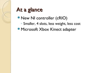
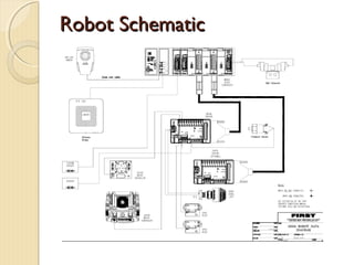
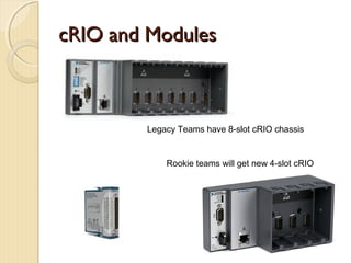
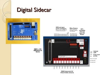
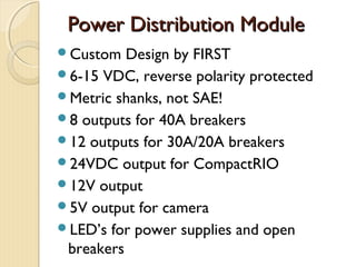
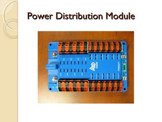
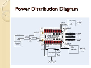
Overview of Electronics
  1425 Wilsonville Robotics


          Tim Bennington-Davis
      tbenningtondavis@ixiacom.com
              (503) 449-9507
At a glance
New   NI controller (cRIO)
 ◦ Smaller, 4 slots, less weight, less cost
Microsoft   Xbox Kinect adapter
Robot Schematic
Elements of the System
National  Instruments cRIO
Digital Sidecar
Power Distribution Board
Analog Bumper
Pneumatics Bumper
Netbook Driver Station
Wireless Interface (802.11)
Camera
Motor controllers and relays
cRIO
ModularController, Industrial Strength
Comes with multiple interface modules
  ◦ 2 Analog Input Modules
    Plus 2 Analog Breakout
  ◦ 2 Digital Input/Output Modules
    Connect via really big cable to Digital Sidecar
  ◦ 1 Digital Output Module
    Use with Solenoid Breakout
Veteran    teams do not get new cRIO’s and
 modules
Rookie teams will get new smaller cRIO
cRIO and Modules


        Legacy Teams have 8-slot cRIO chassis


            Rookie teams will get new 4-slot cRIO
Digital Sidecar
Connects       to cRIO9403 with 32-pin cable
Provides
 ◦ 10 PWM outputs (Victors, Jaguars, RC
   servos)
      Can be configured on a per-output basis to drive
       6V RC servos with jumpers
 ◦   14 GPIO with +5V on each
 ◦   16 Relay Outputs
 ◦   I2C headers (Standard and NXT-compatible)
 ◦   12V supply,
      Provides +5V output
Digital Sidecar
Power Distribution Module
Custom   Design by FIRST
6-15 VDC, reverse polarity protected
Metric shanks, not SAE!
8 outputs for 40A breakers
12 outputs for 30A/20A breakers
24VDC output for CompactRIO
12V output
5V output for camera
LED’s for power supplies and open
 breakers
Power Distribution Module
Power Distribution Diagram
Analog Breakout
5V/3A for powering sensors
8 Analog Inputs, 3 pin PWM cable config.
Mounts to NI 9201 Analog Module
Configurable to make one input capable
 of measuring battery voltage - mandatory
LED to indicate bumper has power
Power to bumper requires wiring to
 power distribution module
Analog Bumper
Pneumatics Breakout
Reverse-battery  protection
8 Outputs to directly drive solenoids
Mounts to NI 9472 Digital Module
Means you don’t have to use Spikes to
 drive solenoids anymore
 ◦ Save weight, space and money
LED  to indicate bumper has power
Power to bumper requires wiring to
 power distribution module, can tolerate
 12v or 24v to match solenoids
Pneumatics Breakout
Wireless Interface – 802.11
Radio   on the robot is 802.11 wireless
 bridge
Check for how to power it correctly from
 your robot
You will assign fixed IP addresses to your
 components, using team number
Use as AP during build season, connect to
 the wired field at the competition
Field will use 5 GHz band to avoid overlap
 and interference
Ethernet Camera – Axis M1011
Streaming   video for drive-
 time control has been
 challenging
Connects to RJ45 on cRIO
Can be used to track colors
Jaguar Motor Controller
Replaces  the venerable Victor
CAN bus interface, limit features
Do NOT remove the power screws
They are “swaged” on the end, which is
 meant to keep them from coming out
Removing them drops metal shavings
 into the guts
Operator Interface
Classmate  Computer or equivalent
  Must run supplied software
  IP connected
  Communicates constantly with cRIO
USB expansion hub
Joysticks (USB)
Cypress pSOC I/O expansion device
Operator Interface
Typically a 48” x 8” console
Joysticks or other driving interface
Buttons, switches, dials, lights
Your team designs and builds it
Effective driving operation is enabled by
 careful ergonomic design, especially
 when it comes to controlling the non-
 drive functions
Operator Interface
Cypress    board provides 16 configurable
 digital pins, 8 analog inputs
Plug into proto board, or build/buy
 carrier board
Digital and analog functions map to
 software
Typical OI Functions
switch  (on/off) – 1 digital input
3 position switch (on/off/on) – 2 digital
 inputs
Potentiometer (variable position) – 1
 analog input
Push button switch (momentary
 contact) – 1 digital input
Indication (LED) – 1 digital output
Link between OI and cRIO
Default  software causes cRIO and
 classmate computer to update each
 other several times a second
All OI data is fed to cRIO automatically
If they don’t talk, your robot disables
 itself
Status of communication shown in
 classmate GUI
Other Handy Parts
10-turn  potentiometers
  Not supplied – Norvac, Fry’s, Digi-Key
  Wire to analog input
US Digital Quadrature Encoders
  Mount in many transmissions
  Count transmission rotation, direction
3-axis accelerometer (supplied)
Gyro (supplied)
Analog Ultrasonic detectors
  For measuring close distances
Helpful Hints
Working the Wago
• Find a Wago tool (Newark Electronics)
• Take care to insert directly at a fixed angle, pressing straight in
• Do not pry. The goal is to open the spring by pressing in the
         screwdriver, not by prying
802.11 Radio Link
The  AP and bridge have changed over
 the years.
Learn how to set static IP addresses on
 your PC, and how to log into AP and
 adapter to configure them manually
Turn off “Wireless Protection”, so that
 inadvertent presses of external buttons
 don’t change settings unexpectedly
Other ideas worth remembering
Solder your terminals – prevent failure
Keep large gauge wiring as short as possible
Lay your electronics out so you can
 troubleshoot it – 2 layers sometimes works
Make a battery charging record
  ◦ During tournaments, know which one is charged
Read  the inspection rules early – a great “cheat
 sheet” for guiding you
 Label your wires or use color markings, to
 make troubleshooting easier
Robot frame is NOT connected to ground
Wrapping Up
Go    to the FIRST website, navigate
 ◦   FRC
 ◦   Game and Season Info
 ◦   Competition
 ◦   Competition Manual and Related Docs
Check out the schematics, rules and
 manuals from last year
 ◦ Wire gauge requirements, terminals, etc.

FIRSTFare 2012 Overview of Electronics

  • 1.
    Overview of Electronics 1425 Wilsonville Robotics Tim Bennington-Davis tbenningtondavis@ixiacom.com (503) 449-9507
  • 2.
    At a glance New NI controller (cRIO) ◦ Smaller, 4 slots, less weight, less cost Microsoft Xbox Kinect adapter
  • 3.
  • 4.
    Elements of theSystem National Instruments cRIO Digital Sidecar Power Distribution Board Analog Bumper Pneumatics Bumper Netbook Driver Station Wireless Interface (802.11) Camera Motor controllers and relays
  • 5.
    cRIO ModularController, Industrial Strength Comeswith multiple interface modules ◦ 2 Analog Input Modules  Plus 2 Analog Breakout ◦ 2 Digital Input/Output Modules  Connect via really big cable to Digital Sidecar ◦ 1 Digital Output Module  Use with Solenoid Breakout Veteran teams do not get new cRIO’s and modules Rookie teams will get new smaller cRIO
  • 6.
    cRIO and Modules Legacy Teams have 8-slot cRIO chassis Rookie teams will get new 4-slot cRIO
  • 7.
    Digital Sidecar Connects to cRIO9403 with 32-pin cable Provides ◦ 10 PWM outputs (Victors, Jaguars, RC servos)  Can be configured on a per-output basis to drive 6V RC servos with jumpers ◦ 14 GPIO with +5V on each ◦ 16 Relay Outputs ◦ I2C headers (Standard and NXT-compatible) ◦ 12V supply,  Provides +5V output
  • 8.
  • 9.
    Power Distribution Module Custom Design by FIRST 6-15 VDC, reverse polarity protected Metric shanks, not SAE! 8 outputs for 40A breakers 12 outputs for 30A/20A breakers 24VDC output for CompactRIO 12V output 5V output for camera LED’s for power supplies and open breakers
  • 10.
  • 11.
  • 12.
    Analog Breakout 5V/3A forpowering sensors 8 Analog Inputs, 3 pin PWM cable config. Mounts to NI 9201 Analog Module Configurable to make one input capable of measuring battery voltage - mandatory LED to indicate bumper has power Power to bumper requires wiring to power distribution module
  • 13.
  • 14.
    Pneumatics Breakout Reverse-battery protection 8 Outputs to directly drive solenoids Mounts to NI 9472 Digital Module Means you don’t have to use Spikes to drive solenoids anymore ◦ Save weight, space and money LED to indicate bumper has power Power to bumper requires wiring to power distribution module, can tolerate 12v or 24v to match solenoids
  • 15.
  • 16.
    Wireless Interface –802.11 Radio on the robot is 802.11 wireless bridge Check for how to power it correctly from your robot You will assign fixed IP addresses to your components, using team number Use as AP during build season, connect to the wired field at the competition Field will use 5 GHz band to avoid overlap and interference
  • 17.
    Ethernet Camera –Axis M1011 Streaming video for drive- time control has been challenging Connects to RJ45 on cRIO Can be used to track colors
  • 18.
    Jaguar Motor Controller Replaces the venerable Victor CAN bus interface, limit features Do NOT remove the power screws They are “swaged” on the end, which is meant to keep them from coming out Removing them drops metal shavings into the guts
  • 19.
    Operator Interface Classmate Computer or equivalent Must run supplied software IP connected Communicates constantly with cRIO USB expansion hub Joysticks (USB) Cypress pSOC I/O expansion device
  • 20.
    Operator Interface Typically a48” x 8” console Joysticks or other driving interface Buttons, switches, dials, lights Your team designs and builds it Effective driving operation is enabled by careful ergonomic design, especially when it comes to controlling the non- drive functions
  • 21.
    Operator Interface Cypress board provides 16 configurable digital pins, 8 analog inputs Plug into proto board, or build/buy carrier board Digital and analog functions map to software
  • 22.
    Typical OI Functions switch (on/off) – 1 digital input 3 position switch (on/off/on) – 2 digital inputs Potentiometer (variable position) – 1 analog input Push button switch (momentary contact) – 1 digital input Indication (LED) – 1 digital output
  • 23.
    Link between OIand cRIO Default software causes cRIO and classmate computer to update each other several times a second All OI data is fed to cRIO automatically If they don’t talk, your robot disables itself Status of communication shown in classmate GUI
  • 24.
    Other Handy Parts 10-turn potentiometers Not supplied – Norvac, Fry’s, Digi-Key Wire to analog input US Digital Quadrature Encoders Mount in many transmissions Count transmission rotation, direction 3-axis accelerometer (supplied) Gyro (supplied) Analog Ultrasonic detectors For measuring close distances
  • 25.
  • 26.
    Working the Wago •Find a Wago tool (Newark Electronics) • Take care to insert directly at a fixed angle, pressing straight in • Do not pry. The goal is to open the spring by pressing in the screwdriver, not by prying
  • 27.
    802.11 Radio Link The AP and bridge have changed over the years. Learn how to set static IP addresses on your PC, and how to log into AP and adapter to configure them manually Turn off “Wireless Protection”, so that inadvertent presses of external buttons don’t change settings unexpectedly
  • 28.
    Other ideas worthremembering Solder your terminals – prevent failure Keep large gauge wiring as short as possible Lay your electronics out so you can troubleshoot it – 2 layers sometimes works Make a battery charging record ◦ During tournaments, know which one is charged Read the inspection rules early – a great “cheat sheet” for guiding you  Label your wires or use color markings, to make troubleshooting easier Robot frame is NOT connected to ground
  • 29.
    Wrapping Up Go to the FIRST website, navigate ◦ FRC ◦ Game and Season Info ◦ Competition ◦ Competition Manual and Related Docs Check out the schematics, rules and manuals from last year ◦ Wire gauge requirements, terminals, etc.