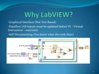
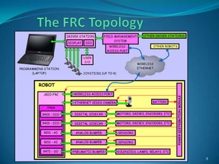
Azure Monitor & Application Insight to monitor Infrastructure & Application
First fare 2010 lab-view overview
1. FIRSTFare 2010LabVIEW Overview Dennis C. Erickson ~ Senior Mentor for Teams 1510 and 2898 Daniel Bramblett ~ Team 1510 Amy Wiegand ~ Team 2915 1
2. Introduction Working with National Instrument’s Hardware and Software Specifically: Software ~ LabVIEW Hardware ~ cRIO 2
3. Introduction LabVIEW VI = Virtual Instrument EW = Engineering Workstation VI = Virtual Instrument or in other languages “Routine”, SubVI = Subroutine 3
8. Advanced set of diagnostic tools; probes, execution highlighting, error reporting, ability to surround the code with a “virtual world simulation environment” for testing.5
11. Easily compiles to RT (Real-time) Operating Systems and FPGA (Field Programmable Gate Arrays) used in the cRIO processor6
12. Why Do More Than Necessary to Win the Contest? While it is entirely possible to win a contest with a robot that is “bare bones” the better goal is to learn how to do things along the way that may or may not be used. 7
14. The SoftwareUsed to Make Stuff Move This section offers a brief short course on the language LabVIEW 9
15. To start a new project Launch LabVIEW to create a new project 10
16. To start a new project Name your project . You might for example use your team name and year in the name: i.e., “Team 1510 for 2010 Robot Project” Be sure that you enter your team IP in the following format: 10.15.10.02 11
17. To start a new project Adding a VI to your project: If its new, then right-click to “VI” and select and name it. If adding an existing one select the menu item “Add”. 12
18. LabVIEW Functions - Front Panel Some example controls and indicators for the Front Panel 13 Numerical Controls and Indicators
19. LabVIEW Functions - Front Panel Some example controls and indicators for the Front Panel 14 Booleans
20. LabVIEW Functions - Front Panel Some example controls and indicators for the Front Panel 15 Strings and Paths
21. LabVIEW Functions - Front Panel Some example controls and indicators for the Front Panel 16 Arrays, Clusters, Matrices and Dialog Boxes
22. LabVIEW Functions - Front Panel Some example controls and indicators for the Front Panel 17 List Boxes, Tables and Trees
23. LabVIEW Functions - Front Panel Some example controls and indicators for the Front Panel 18 2D, 3D Digital Charts and Graphs and Special Plots
24. LabVIEW Functions - Front Panel Some example controls and indicators for the Front Panel 19 Rings and Enums
25. LabVIEW Functions - Diagram Some example controls and indicators for the Diagram 20 Structures
26. LabVIEW Functions - Diagram Some example controls and indicators for the Diagram 21 Arrays
27. LabVIEW Functions - Diagram Some example controls and indicators for the Diagram 22 Structures, Classes and Variants
28. LabVIEW Functions - Diagram Some example controls and indicators for the Diagram 23 Numerics, Booleans and Files
29. LabVIEW Functions - Diagram Some example controls and indicators for the Diagram 24 Timing, Dialog Boxes, Waveforms, etc, etc Hundreds of other functions
30. An Example of Virtual Testing Testing the Joystick Power Function VI 25 Task: Test the VI with 1000 simulated Joystick positions from 0 to +1 to 0 to -1 (White Line) and create 9 plots with the following function: Plotn = (motor speed)m Where: Plotn = a series of plots (9 total) Motor speed = voltage input to the motor (from 1 to -1) m = power function (use to alter the forward sensitivity of the Joystick)
33. The DS Drive Station (Link from the User to the robot’s brain)26
34. cRIO Hardware cRIO – Compact Real-time Input/Output A PAC (Programmable Automation Controller) which is an industrial controller that is used in advanced systems incorporating software capabilities such as control, communication, data logging, and signal processing requiring rugged hardware performing logic, motion, process control, and vision. For FIRST applications, ideal for robot building. 27 A fully populated cRIO example
35. cRIO Hardware Real-time operating system 28 cRIO connected to a Laptop FPGA – Field Programmable Gate Array located under the cRIO chassis
36. How to Set up a Virtual Test Environment The following Example code shows how to create an environment to test and calibrate VI modules. In this case we are testing the Camera Servo motors 29 Next run the test in a While loop. Note the Loop Sweep constant which defines the loop cycle (20ms). Here the loop is stopped using the Stop Test? command First Initialize the test (note the “Data Dependency” wire) Finally End the test by closing all references, etc. Again note the Data Dependency and use of a Frame structure as the SubVI has no wired input to use
37. State Diagrams The following slides start with a State Chart to show what the State Diagram will do. The next slides show the State Diagram created. 30
38. State Diagrams 31 State diagrams are extremely useful in creating small or large applications. Since LabVIEW is a DataFlow language, this approach adds to the robustness of the application The Application starts by selecting the Initialize Test State (case). Note that we check for errors and if the Stop Test? Button is pressed. Note that the Enum (far left constant control) has 3 possible states; Initialize Test, Run Test and End Test
39. State Diagrams 32 These slides show a typical State Diagram that tests camera servos. Note the inputs from the joystick and a smoothing control to test filtering. Next if no errors, run the While loop until an error happens or the Stop Test? Button is pressed the go to the next State
40. State Diagrams One of the interesting features of the State Diagram is confining the application code to one screen, thus self documenting code 33 Finally, there has been an error or the Stop Test? Button has been pressed so end the test by closing references, etc. Note that now the Boolean constant is now TRUE which stops the loop