Download to read offline

![International Research Journal of Engineering and Technology (IRJET) e-ISSN: 2395-0056
Volume: 11 Issue: 02 | Feb 2024 www.irjet.net p-ISSN: 2395-0072
© 2023, IRJET | Impact Factor value: 8.226 | ISO 9001:2008 Certified Journal | Page 59
2. LITERATURE SURVEY
In his article titled "CIC Filter Introduction," Matthew P.
Donadio [3] highlights theincreasingimportanceofcascaded
integrator-comb filters in modern Digital Signal Processing
(DSP) systems. As data converters continue to advance in
speed, the need for narrow-band extraction from wideband
sources and narrow-band construction of wideband signals
becomes critical. Accomplishing these tasks relies on
fundamental signal processing techniques like decimation
and interpolation. Despite the advancement in digital
hardware speed,thedemandforefficientsolutionspersists.It
was Hogenauer [1] who developed the CIC filters to address
this challenge. These versatile and multiplier-free filters are
well-suited for hardware implementation and can handle
arbitrary and significant rate changes effectively.
The CIC filter can be efficiently implemented using a moving
average filter with NR taps, followedbyoutputdecimationby
a factor of R. Similarly, an interpolating CIC filter utilizes an
NR tap moving average filter operating at the output sample
rate, with R-1 zero samples inserted between each input
sample [2]. The beauty of CICfilters lies in their simplicity,as
they exclusively employ additions and subtractions for their
arithmetic operations. As describedbytheauthors,CICfilters
are technically lean, mean, and efficient filtering machines,
making them highly effective in their functionality.
Researchers have optimized the hardware required for
implementing CIC decimator and interpolator structures.
Through a combination of modal analysis, MATLAB
simulations, and FPGA synthesis using Xilinx ISE, they
validate their results while exploring different rate factors
and stage configurations. Thedevice utilization summaryfor
decimators and interpolators with varying stages is
presented using the Xilinx Spartan 3 FPGA [4].
The challenge of handling high-frequency transmission
signals and implementing decimation with FIR or IIR filters
arises due to the significant cost associated with purchasing
numerous multipliers. In response to this challenge, a
practical solution has been devised in the form of a five-stage
CIC filter that eliminates the need for multipliers. This
innovative structure finds its primary application in Digital
Signal Processing (DSP) applications [5]. By using the CIC
filter without multipliers, the cost and complexity of the
implementation are significantly reduced while maintaining
effective decimation of high-frequency signals.
The efficiency of conversions by odd factors compared to
even factors in the class of linear-phase FIR Mth-band filters
has been demonstrated. For odd factors, the proposed
structures are more efficient and can be derived from
conventional two-stage structures. In contrast, recently
created add-equalize structures, which are also capable of
arbitrary-integerconversion,exhibitcomparablecomplexity
to conventional multi-stage converters (when applicable),
but are not more effective for odd M comparedtoevenM[6].
The findings indicate that the proposed structures
outperform these add-equalize structures,especiallyforodd
conversion factors, offering improved efficiency in the
context of linear-phase FIR Mth-band filters.
Jun Woo Kim et al. [7] introduced a reliablePRACHdetection
method that remains dependable regardless of the search
time offset. While this method takes twice as long to search
for PRACH, the latency of PRACH detection is not a
significant concern in modem design since the detection
process occurs only once per frame. Despite the longer
search time, the PRACH detector proposed in the study
accurately identifies the optimal UL (Uplink) start point for
the anticipated channel model in the intended service, as
confirmed by simulation results. This highlights the
effectiveness andprecisionoftheproposedPRACHdetection
method.
Tuan Anh Pham and Bang Thanh Le present an enhanced
algorithm in their work [8], aimed at effectively mitigating
false alarm peaks caused by various factors, such as noise
and adverse channel conditions like multipath fading,
Doppler shift, frequency offset, and timing offset. The
proposed method employs multiple detection steps to
achieve this objective. By optimizing detection thresholds,
the algorithm fulfills the system's specific requirements
concerning detection probabilityandfalsealarmprobability,
especially under different Signal-to-Noise Ratio(SNR)levels
and varying propagation conditions. Throughthisapproach,
the authors successfully address the challenges posed by
noisy and dynamic channel environments, enhancing the
overall performance of the system.
A continuous-time signal is a signal that is present at all
points in time because there are an infinite number of time
instances separating any two points in space. A continuous-
time signal is sampled at specific, predetermined time
instants to produce a discrete-time signal, in contrast. The
corresponding samples represent the values of the signal,
and the sample times indicate when the signal is defined.
The Nyquist-Shannon sampling theorem mathematically
limits the sampling rate by stating that the minimum
sampling rate should be at least twice the maximum
frequency of the signal being sampled. As a result, it is
possible to successfully recovertheoriginal continuous-time
signal.
Consider, for instance, a signal that continuously changes in
frequency from f1 to f2, with f1 being the lowest frequency
and f2 being the highest. The minimum sampling frequency
needed to accurately recover the original continuous-time
signal is 2*f2.
With the aid of various signal processing techniques,suchas
sample and hold circuits and low-pass filters, the original
continuous-time signal can be recovered from its samples.](https://image.slidesharecdn.com/irjet-v11i210-241024054830-20469d18/85/FIR-filter-based-Sample-Rate-Convertors-and-its-use-in-NR-PRACH-2-320.jpg)
![International Research Journal of Engineering and Technology (IRJET) e-ISSN: 2395-0056
Volume: 11 Issue: 02 | Feb 2024 www.irjet.net p-ISSN: 2395-0072
© 2023, IRJET | Impact Factor value: 8.226 | ISO 9001:2008 Certified Journal | Page 60
The particulars of these methods are outside the purview of
this discussion.
Handling high-rate samples requires more hardware
memory and processing power. Modifying the sample rate
becomes a crucial technique in signal processing systems,
depending on the hardware resources available. When
operating with constrained hardware, lower sample rates
are preferred. This method is useful in fields like image
scaling and audio/visual systems, where various sampling
rates may be used for technical, practical, or even historical
reasons.
The process of changing a discrete signal's sampling rate or
frequency to produce a new discrete representation of the
underlying continuous signal is known as sample-rate
conversion. Interpolation, or upsampling, refers to the
process of going from a lower rate to a higher rate by adding
more samples to guarantee better signal quality. On the
other hand, decimation or downsampling refers to the
removal of samples when going from a higher ratetoa lower
rate to save memory, processing power, and time resources.
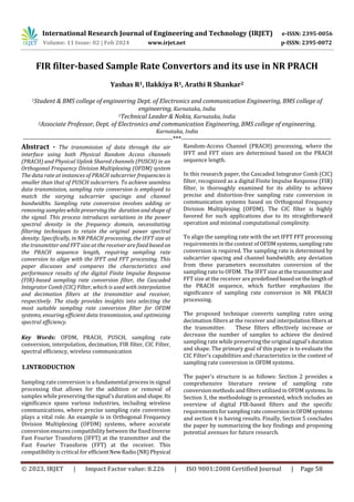
2. METHODOLOGY
2.1 Sampling rate conversion's effects on signal's
time-frequency characteristics
Sampling rate conversion has a significant impact on a
signal's time and frequency domains. To be successful, the
original signal's desired properties must always be
maintained.
Interpolation:
Time domain impacts:
When interpolation is done, extra samples are
added to the original sample set, increasing the information
content and possibly raising the signal's quality. However,
because there are more samples, this also results in more
storage space being needed and slower processing.
Frequency domain impacts:
The frequency-domain characteristics of the signal
can be significantly altered by interpolation as well as
decimation. As more samples are added, the interpolation
process introduces amplitude variations in the newly
inserted samples. At integer multiples of the original
sampling rate, copies of the original spectrumstarttoappear
as a result.
Zero-valued samples are first added between the original
samples to begin the interpolation process. The original
spectrum is reproduced at integer multiples of the original
sampling rate as a result of these abrupt amplitude
variations. This phenomenon can be seen in the upsampled
signal's spectral features, where the original spectrum's
copies at these integer multiples become very obvious.
Decimation:
Time domain impacts:
Decimation involves removing samples from the
original sample set, which could lead to a decrease in signal
quality and information content. However, it has benefits
like less storage space and quicker processing.
Frequency domain impacts:
Decimation also affects the signal's spectral
characteristics. Making sure that the newly reduced
sampling rate can faithfully capture all of the spectral
properties of the original signal presents a challenge during
decimation. Aliasing can happen if the original signal
contains frequency components that are higher than the
range that can be represented by the slower sampling rate.
Aliasing is the process offoldingfrequencycomponentsback
into the relevant band, which can lead to distortions in the
signal's spectral properties.
For example, when downsampling a signal by a factor of
four, if the original signal contains a frequency component
(CIC) filter, The CIC filter can deal with indeterminate and
large rate changes effectively.
Fig -1: A Cascaded integrator-comb implementation of a
D-point recursive running sum filter.
The comb section and the integrator are the two
fundamental building blocks that make up the CICfilter. The
feedforward portion, also referred to as the comb section,
includes a differential delay denoted by the letter D. The
integrator, on the other hand, refers to the feedback section.
The current input sample is subtracted from a delayedinput
sample in the comb stage. The integrator functions as an
accumulator.
The difference equation representing the time-domain
behavior of the CIC filter is given by:
y(n) = x(n) – x(n–D) + y(n–1) (1)
Mathematically, the integrator and comb circuits can be as
follows, where x [n] is the input and y [n] is the output, with
a differential delay of D:
Integrator: y[n] = y[n-1] + x[n] (2)
Comb: y[n] = x[n] - x[n-D] (3)](https://image.slidesharecdn.com/irjet-v11i210-241024054830-20469d18/85/FIR-filter-based-Sample-Rate-Convertors-and-its-use-in-NR-PRACH-3-320.jpg)
![International Research Journal of Engineering and Technology (IRJET) e-ISSN: 2395-0056
Volume: 11 Issue: 02 | Feb 2024 www.irjet.net p-ISSN: 2395-0072
© 2023, IRJET | Impact Factor value: 8.226 | ISO 9001:2008 Certified Journal | Page 62
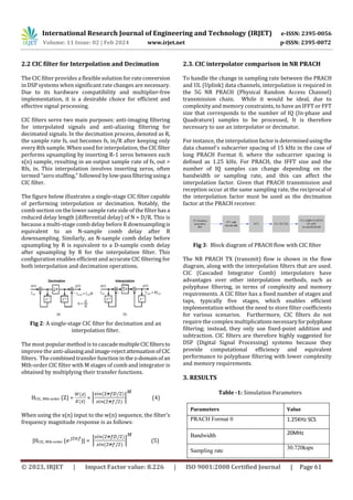
IFFT size
2048
No. of IQ samples after Up-sampling
24576 (as per
3GPP 38.211)
No.of CP samples
3168 (as per
3GPP 38.211)
Interpolation factor (R)
12
In figure the frequency response of CIC filter is sharp and the
phase is liner compared to polyphase filter. By this we can
say that the CIC filter has the better frequency response than
polyphase filter.
Fig 4: Frequency response plot comparison between
Polyphase and CIC
3. CONCLUSIONS
By incorporating the CIC Up-sampling filter in PRACH, the
problem of frequency mismatchbetweenPRACHandPUSCH
subcarriers is resolved. The up-sampling process enables
synchronization, aligns the frequencies, and maintains the
integrity of the PRACH signal in the time domain. This
ensures reliable transmission of data through the air
interface using both PRACH and PUSCHchannelsatthesame
data rate.
ACKNOWLEDGEMENT
Heart full thanks to Ms. Ilakkiya R, Technical Leader, Mobile
Networks, Nokia, for their guidance and support.
REFERENCES
[1] E. B. Hogenauer, “An economical class of digital filters
for decimation and interpolation.” IEEETransactionson
Acoustics, Speech, and Signal Processing, ASSP-
29(2):155–162, 1981
[2] Lyons, R., "A Beginner's Guide to Cascaded Integrator-
Comb (CIC) Filters". Available online at:
https://mycourses.aalto.fi/pluginfile.php/1588221/mo
d_folder/intro/CIC_digital_filters-Lyons.pdf
[3] Matthew P. Donadio, CIC Filter Introduction, July 18,
2000. For free publication by the Iowan.
[4] R. Bhakthavatchalu, V. S. Karthika, L. Ramesh, and B.
Aamani, "Design of optimized CIC decimator and
interpolator in FPGA," 2013 International Multi-
Conference on Automation,Computing,Communication,
Control, and Compressed Sensing (iMac4s), Kottayam,
India, 2013, pp. 812–817, doi:
10.1109/iMac4s.2013.6526518.
[5] Sabitha, D., and Hariharan, K. (2014). “Design of a five-
stage CIC decimation filter for signal processing
applications”. 2014 , pp. 7–3566,
doi:10.129888/ces.2014.4213.
[6] H. Johansson and H. Göckler, "Two-Stage-Based
Polyphase Structures for Arbitrary-Integer Sampling
Rate Conversion," in IEEE Transactions on Circuits and
Systems II: Express Briefs, vol. 62, no. 5, pp. 486-490,
May 2015, doi: 10.1109/TCSII.2015.2389291.
[7] J. W. Kim, Y. S. Lee, M. Y. Jin, B. Seungjae, J.-w. Moon, and
H. Lee, "A Method of PRACH Detection in mmWave 5G
Communications Systems," 2022 13th International
Conference on Information and Communication
Technology Convergence (ICTC), Jeju Island, Korea,
Republic of, 2022, pp. 718–720, doi:
10.1109/ICTC55196.2022.9952541.
[8] Tuan Anh Pham, Bang Thanh Le, "A proposed preamble
detection algorithm for 5G-PRA," 2019 International
Conference on Advanced Technologies for
Communications (ATC), Hanoi, Vietnam, 2019, p. 210–
21444, doi: 10.1109/ATC.2019.8924502.](https://image.slidesharecdn.com/irjet-v11i210-241024054830-20469d18/85/FIR-filter-based-Sample-Rate-Convertors-and-its-use-in-NR-PRACH-5-320.jpg)

The document discusses the role of finite impulse response (FIR) filters, specifically cascaded integrator-comb (CIC) filters, in sampling rate conversion essential for efficient data transmission in orthogonal frequency division multiplexing (OFDM) systems, focusing on new radio (NR) physical random access channel (PRACH) processing. It examines various methodologies, their impact on signal quality, and compares performance results of different filtering techniques to identify optimal choices for spectral efficiency. The study concludes by outlining future research directions based on the findings related to digital signal processing in wireless communications.