Download to read offline
![Band Pass Filter [ BPF ]
Aband-pass filter or BPF, is a device that passes frequencies within a
certain range and rejects frequencies outside that range.
These filters can also be created by combining a low-pass filter with a
high-pass filter.
An ideal band-pass filter would have a completely flat passband (e.g. with
no gain/attenuation throughout) and would completely attenuate all
frequencies outside the passband. Additionally, the transition out of the
passband would have brickwall characteristics.
In practice, no band-pass filter is ideal. The filter does not attenuate all
frequencies outside the desired frequency range completely; in particular,
there is a region just outside the intended passband where frequencies
are attenuated, but not rejected.](https://image.slidesharecdn.com/firbpf-191109031255/85/Finite-Impulse-Response-Band-Pass-Filter-2-320.jpg)
![Finite Impulse Response [ FIR ]
In signal processing, a finite impulse response (FIR) filter is a
filter whose impulse response (or response to any finite
length input) is of finite duration, because it settles to zero in
finite time. This is in contrast to infinite impulse response
(IIR) filters, which may have internal feedback and may
continue to respond indefinitely (usually decaying). A direct form discrete-time FIR filter of
order N. The top part is an N-stage delay line
with N + 1 taps. Each unit delay is a Z-
inverse operator in Z-transform notation.](https://image.slidesharecdn.com/firbpf-191109031255/85/Finite-Impulse-Response-Band-Pass-Filter-3-320.jpg)
![Initialization
```
% Sampling Frequency
Fs= 18000;
% Band Limit 4kHz - 6 kHz
Passband= [4000 6000];
% Magnitude for Passband and Stopband
Magnitudes= [1 0];
% Passband Ripple and Stopband Ripple
Deviations= [0.04 0.01];
```
Kaiser Order
For Kaiser Window, we need a beta (ɞ) value.
Which will be used for Bessel function I˳(ɞ).
Instead of taking arbitrary value of beta, we used
“Kaiser Order Function” to determine it’s value.
```
[N, Wn, beta, ftype]= kaiserord(Passband,
Magnitudes, Deviations, Fs);
```](https://image.slidesharecdn.com/firbpf-191109031255/85/Finite-Impulse-Response-Band-Pass-Filter-5-320.jpg)
![Filter Preparation
% Suitable Frequency Constraints for FIR
filter
wn=[Passband(1) Passband(2)]/(Fs/2);
Filter= fir1(n, wn, 'bandpass', Window);
% Calculated Group Delay: 5.5 samples
% Calculated Phase Delay: 5.5 samples](https://image.slidesharecdn.com/firbpf-191109031255/85/Finite-Impulse-Response-Band-Pass-Filter-7-320.jpg)
![Reference
[1] Wikipedia- The Free Encyclopedia [www.Wikipedia.org]
[2] Mathworks India- MATLAB Documentation [in.mathworks.com]
[3] Scipy Cookbook- SciPy Python Documentation [scipy-
cookbook.readthedocs.io]
[4] University of Colorado Colorado Springs Open Education Library
[5] Digital Signal Processing- Pearson Publication- Fourth Edition by John J.
Proakis & Dimitris G. Manolakis](https://image.slidesharecdn.com/firbpf-191109031255/85/Finite-Impulse-Response-Band-Pass-Filter-10-320.jpg)


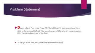
This document discusses the design and implementation of a band pass finite impulse response (FIR) filter in MATLAB. It begins with background on band pass filters and FIR filters. It then states the problem of designing an 11th order band pass FIR filter with a pass band of 4-6kHz using a Kaiser window and sampling rate of 18kHz. The document shows the MATLAB code used to initialize filter parameters, design the Kaiser window, create the FIR filter, and apply it to sample signals to filter between 4-6kHz. It plots the frequency response and filtered output.