Final report
•
0 likes•38 views

Ravi Singh completed an industrial training at NTPC Badarpur power station. He thanks the staff who provided guidance during his training, particularly Mr. Mahendra Singh Chabra and Mr. Anant Kumar Varshney. NTPC was established in 1975 and has expanded significantly, with plans to reach 75,000 MW of capacity by 2017. Badarpur power station meets over 24% of Delhi's electricity needs with its 720 MW installed capacity. The report provides overviews of the basic principles of thermal power generation, control and instrumentation labs, distributed control systems, and other key components and processes at NTPC power stations.

Recommended
More Related Content
What's hot
What's hot (20)
Similar to Final report
Similar to Final report (20)
Recently uploaded
Recently uploaded (20)
Final report
- 1. INDUSTRIAL TRAINING REPORT NTPC BADARPUR SUBMITTED BY: RAVI SINGH ELECTRONICS AND INSTRUMENTATION NIT AGARTALA
- 2. ACKNOWLEDGEMENT With profound respect and gratitude, I take the opportunity to convey my thanks to complete the training here. I do extend my heartfelt thanks to Mr MAHENDRA SINGH CHABRA (A.G.M ELECTRICAL) for providing me this opportunity to be a part of this esteemed organization. I convey my gratitude and sincere thanks to Mr ANANT KUMAR VARSHNEY for guidance and kind help extended to me in order to successfully complete my training by providing with adequate information required. I am extremely grateful to all the technical staff of BTPS/NTPC for their co-operation and guidance that helped me a lot during the course of training. I have learnt a lot working under them and I will always be indebted of them for this value addition in me.
- 3. Overview of NTPC NTPC was set up in the central sector in the 1975. NTPC has installed capacity of 29,394 MW. It plans to be a 75, MW company by 2017. NTPC Badarpur station has also bagged ISO 9001/ ISO 14001 certification. Today NTPC contributes more than 3 / 5th of the total power generation in India.
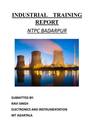
- 4. Overview of BTPS BTPS MEETS MORE THAN 24% OF DELHI’S ELECTRICITY CONSUMPTION INSTALLED CAPACITY 720 MW DERATED CAPACITY 705 MW (3x95 + 2x210MW) OWNED BY GOVT. OF INDIA, MINISTRY OF POWER BEING MANAGED BY NTPC FOR THE LAST 26 YEARS SINCE 1st APRIL 1978 NTPC adjudged as the 3rd best employer in India
- 5. Basic Principle There are basically three main units of a thermal power plant: 1. Steam Generator or Boiler 2. Steam Turbine 3. Electric Generator
- 6. C&I LABS Control and Instrumentation Department ha following labs: 1. Manometry Lab 2. Protection and Interlocks Lab 3. Automation Lab 4. Electronics Lab 5. Water Treatment Plant 6. Furnaces Safety Supervisory System Lab
- 7. Distributed control system A distributed control system (DCS) refers to a control system usually of a manufacturing system , process or any kind of dynamic system, in which the controller elements are not central in location (like the brain) but are distributed throughout the system with each component sub-system controlled by one or more controllers. DCS (Distributed Control System) is a computerized control system used to control the production line in the industry The entire system of controllers is connected by networks for communication and monitoring. DCS is a very broad term used in a variety of industries, to monitor and control distributed equipment. Electrical power grids and electrical generation plants Environmental control systems Traffic signals Radio signals Water management systems Oil refining plants Metallurgical process plants Chemical plants Pharmaceutical manufacturing Sensor networks Dry cargo and bulk oil carrier ships A DCS typically uses custom designed processors as controllers and uses both proprietary interconnections and communications protocol for communication. Input and output modules form component parts of the DCS. The processor receives information from input modules and sends information to output modules. The input modules receive information from input instruments in the process (or field) and transmit instructions to the output instruments in the field. Computer buses or electrical buses connect the processor and modules through multiplexer or demultiplexers. Buses also connect the distributed controllers with the central controller and finally to the Human–machine interface (HMI) or control consoles. See Process automation system. The elements of a DCS may connect directly to physical equipment such as switches, pumps and valves and to Human Machine Interface (HMI) via SCADA. The differences between a DCS and SCADA is often subtle, especially with advances in technology allowing the functionality.
- 8. Flow measurement Flow measurement is the quantification of bulk fluid movement. Flow can be measured in a variety of ways. Positive-displacement flow meters accumulate a fixed volume of fluid and then count the number of times the volume is filled to measure flow. Other flow measurement methods rely on forces produced by the flowing stream as it overcomes a known constriction, to indirectly calculate flow. Flow may be measured by measuring the velocity of fluid over a known area Venturi meter A Venturi meter constricts the flow in some fashion, and pressure sensors measure the differential pressure before and within the constriction. This method is widely used to measure flow rate in the transmission of gas through pipelines, and has been used since Roman Empire times.The coefficient of discharge of Venturi meter ranges from 0.93 to 0.97. The first large-scale Venturi meters to measure liquid flows were developed by Clemens Herschel who used them to measure small and large flows of water and wastewater beginning at the end of the 19th century Orifice plate An orifice plate is a plate with a hole through it, placed in the flow; it constricts the flow, and measuring the pressure differential across the constriction gives the flow rate. It is basically a crude form of Venturi meter, but with higher energy losses. There are three type of orifice: concentric, eccentric, and segmenta Level to flow The level of the water is measured at a designated point behind weir or in flume a hydraulic structure using various secondary devices (bubblers, ultrasonic, float, and differential pressure are common methods). This depth is converted to a flow rate according to a theoretical formula of the form where is the flow rate, is a constant, is the water level, and is an exponent which varies with the device used; or it is converted according to empirically derived level/flow data points (a "flow curve"). The flow rate can then integrated over time into volumetric flow. Level to flow devices are commonly used to measure the flow of surface waters (springs, stream, and rivers), industrial discharges, and sewage. Of these, weirs are used on flow streams with low solids (typically surface waters), while flumes are used on flows containing low or high solids contents
- 9. Pressure measurement Many techniques have been developed for the measurement of pressure and vacuum. Instruments used to measure pressure are called pressure gaugesor vacuum gauges. A manometer could also refer to a pressure measuring instrument, usually limited to measuring pressures near to atmospheric. The term manometer is often used to refer specifically to liquid column hydrostatic instruments. A vacuum gauge is used to measure the pressure in a vacuum—which is further divided into two subcategories, high and low vacuum (and sometimesultra-high vacuum). The applicable pressure range of many of the techniques used to measure vacuums have an overlap. Hence, by combining several different types of gauge, it is possible to measure system pressure continuously from 10 mbar down to 10−11 mbar. Bourdon The Bourdon pressure gauge uses the principle that a flattened tube tends to straighten or regain its circular form in cross-section when pressurized. Although this change in cross- section may be hardly noticeable, and thus involving moderate stresses within the elastic range of easily workable materials, the strain of the material of the tube is magnified by forming the tube into a C shape or even a helix, such that the entire tube tends to straighten out or uncoil, elastically, as it is pressurized. Eugene Bourdon patented his gauge in France in 1849, and it was widely adopted because of its superior sensitivity, linearity, and accuracy; Edward Ashcroft purchased Bourdon's American patent rights in 1852 and became a major manufacturer of gauges. Also in 1849, Bernard Schaeffer in Magdeburg, Germany patented a successful diaphragm (see below) pressure gauge, which, together with the Bourdon gauge, revolutionized pressure measurement in industry.[6] But in 1875 after Bourdon's patents expired, his company Schaeffer and Budenberg also manufactured Bourdon tube gauges DPharp Digital Transmitters a new standard for accuracy, stability and robustness. Yokogawa has more than 45 years' experience in the development, design, and manufacture of pressure sensors and pressure transmitters and differential pressure transmitters. The DPharp series of digital pressure transmitters use a differential pressure high accuracy resonance (DPharp) sensor that represents one of the most revolutionary advances in transmitter technology.
- 10. Resistance thermometer Resistance thermometers, also called resistance temperature detectors ('RTD's), are sensors used to measure temperature by correlating the resistance of the RTD element with temperature. Most RTD elements consist of a length of fine coiled wire wrapped around a ceramic or glass core. The element is usually quite fragile, so it is often placed inside a sheathed probe to protect it. The RTD element is made from a pure material, typically platinum, nickel or copper. The material has a predictable change in resistance as the temperature changes; it is this predictable change that is used to determine temperature. They are slowly replacing the use of thermocouples in many industrial applications below 600 °C, due to higher accuracy and repeatability Two-wire configuration The simplest resistance thermometer configuration uses two wires. It is only used when high accuracy is not required, as the resistance of the connecting wires is added to that of the sensor, leading to errors of measurement. This configuration allows use of 100 meters of cable. This applies equally to balanced bridge and fixed bridge system. Three-wire configuration In order to minimize the effects of the lead resistances, a three-wire configuration can be used. Using this method the two leads to the sensor are on adjoining arms. There is a lead resistance in each arm of the bridge so that the resistance is cancelled out, so long as the two lead resistances are accurately the same. This configuration allows up to 600 meters of cable. Four-wire configuration The four-wire resistance thermometer configuration increases the accuracy and reliability of the resistance being measured: the resistance error due to lead wire resistance is zero. In the diagram above a standard two-terminal RTD is used with another pair of wires to form an additional loop that cancels out the lead resistance. The above Wheatstone bridge method uses a little more copper wire and is not a perfect solution. Below is a better configuration, four- wire Kelvin connection. It provides full cancellation of spurious effects; cable resistance of up to 15 Ω can be handled.
- 11. Electricity generation Turbo generator Electricity generation is the process of generating electrical power from other sources of primary energy. The fundamental principles of electricity generation were discovered during the 1820s and early 1830s by the British scientist Michael Faraday. His basic method is still used today: electricity is generated by the movement of a loop of wire, or disc of copper between the poles of a magnet.[1] For electric utilities, it is the first process in the delivery of electricity to consumers. The other processes, electricity transmission,distribution, and electrical power storage and recovery using pumped-storage methods are normally carried out by the electric power industry. Electricity is most often generated at a power station by electromechanical generators, primarily driven by heat engines fueled by chemical combustion or nuclear fission but also by other means such as the kinetic energy of flowing water and wind. Other energy sources include solar photovoltaics and geothermal power.
- 12. With the massive expansion of power generation, there is also growing awareness among all concerned to keep the pollution under control and preserve the health and quality of the natural environment in the vicinity of the power stations. NTPC is committed to provide affordable and sustainable power in increasingly larger quantity. NTPC is conscious of its role in the national endeavour of mitigating energy poverty, heralding economic prosperity and thereby contributing towards India’s emergence as a major global economy. Lay out of Employee’s Overall Power Generation The table below shows the detailed operational performance of coal based stations over the years. The energy conservation parameters like specific oil consumption and auxiliary power consumption have also shown considerable improvement over the years. THERMAL POWER PLANT A Thermal Power Station comprises all of the equipment and a subsystem required to produce electricity by using a steam generating boiler fired with fossil fuels or befouls to drive an electrical generator. Some prefer to use the term ENERGY CENTER because such facilities convert forms of energy, like nuclear energy, gravitational potential energy or heat energy (derived from the combustion of fuel) into electrical energy. Unit 1997-98 2006-07 % of increase Installed Capacity MW 16,847 26,350 56.40 Generation MUs 97,609 1,88,674 93.29 No. of employees No. 23,585 24,375 3.34 Generation/employee MUs 4.14 7.74 86.95 OPERATIONAL PERFORMANCE OF COAL BASED NTPC STATIONS Unit 97-98 98-99 99-00 00-01 01-02 02-03 03-04 04-05 05-06 06-07 Generation BU 106.2 109.5 118.7 130.1 133.2 140.86 149.16 159.11 170.88 188.67 PLF % 75.20 76.60 80.39 81.8 81.1 83.6 84.4 87.51 87.54 89.43 Availability Factor % 85.03 89.36 90.06 88.54 81.8 88.7 88.8 91.20 89.91 90.09
- 13. , POWER PLANT is the most common term in the united state; While POWER STATION prevails in many Commonwealth countries and especially in the United Kingdom. Such power stations are most usually constructed on a very large scale and designed for continuous operation. Typical diagram of a coal fired thermal power station 1. Cooling water pump 2. Three-phase transmission line 3. Step up transformer 4. Electrical Generator 5. Low pressure steam 6. Boiler feed water pump 7. Surface condenser 8. Intermediate pressure steam turbine 9. Steam control valve 10. High pressure steam turbine 11. Deaerator Feed water heater 12. Coal conveyor 13. Coal hopper 14. Coal pulverizer 15. boiler steam drum 16. Bottom ash hoper 17. Super heater 18. Forced draught(draft) fan 19. Reheater 20. Combustion air intake 21. Economizer 22. Air preheater 23. Precipitator 24. Induced draught(draft) fan 25. Fuel gas stack The description of some of the components written above is described as follows: 1. Cooling towers Cooling Towers are evaporative coolers used for cooling water or other working medium to near the ambivalent web-bulb air temperature. Cooling tower use evaporation of water to reject heat from processes such as cooling the circulating water used in oil refineries, Chemical plants, power plants and building cooling, for example. The tower vary in size from small roof-top units to very large hyperboloid structures that can be up to 200 meters tall and 100 meters in diameter, or rectangular structure that can be over 40 meters tall and 80 meters long. Smaller towers are normally factory built, while larger ones are constructed on site. The primary use of large , industrial cooling tower system is to remove the heat absorbed in the circulating cooling water systems used in power plants , petroleum
- 14. refineries, petrochemical and chemical plants, natural gas processing plants and other industrial facilities . The absorbed heat is rejected to the atmosphere by the evaporation of some of the cooling water in mechanical forced-draft or induced draft towers or in natural draft hyperbolic shaped cooling towers as seen at most nuclear power plants. 2.Three phase transmission line Three phase electric power is a common method of electric power transmission. It is a type of polyphase system mainly used to power motors and many other devices. A Three phase system uses less conductor material to transmit electric power than equivalent single phase, two phase, or direct current system at the same voltage. In a three phase system, three circuits reach their instantaneous peak values at different times. Taking one conductor as the reference, the other two current are delayed in time by one-third and two-third of one cycle of the electrical current. This delay between “phases” has the effect of giving constant power transfer over each cycle of the current and also makes it possible to produce a rotating magnetic field in an electric motor. At the power station, an electric generator converts mechanical power into a set of electric currents, one from each electromagnetic coil or winding of the generator. The current are sinusoidal functions of time, all at the same frequency but offset in time to give different phases. In a three phase system the phases are spaced equally, giving a phase separation of one-third one cycle. Generators output at a voltage that ranges from hundreds of volts to 30,000 volts. At the power station, transformers: step-up” this voltage to one more suitable for transmission. After numerous further conversions in the transmission and distribution network the power is finally transformed to the standard mains voltage (i.e. the “household” voltage). The power may already have been split into single phase at this point or it may still be three phase. Where the step-down is 3 phase, the output of this transformer is usually star connected with the standard mains voltage being the phase-neutral voltage. Another system commonly seen in North America is to have a delta connected secondary with a center tap on one of the windings supplying the ground and neutral. This allows for 240 V three phase as well as three different single phase voltages( 120 V between two of the phases and neutral , 208 V between the third phase ( known as a wild leg) and neutral and 240 V between any two phase) to be available from the same supply. 3.Electrical generator An Electrical generator is a device that converts kinetic energy to electrical energy, generally using electromagnetic induction. The task of converting the electrical energy into mechanical energy is accomplished by using a motor. The source of mechanical energy may be a reciprocating or turbine steam engine, , water falling through the turbine are made in a variety of sizes ranging from small 1 hp (0.75 kW) units (rare) used as mechanical drives for pumps, compressors and other shaft driven equipment , to 2,000,000 hp(1,500,000 kW) turbines used to generate electricity. There are several classifications for modern steam turbines. Steam turbines are used in all of our major coal fired power stations to drive the generators or alternators, which produce electricity. The turbines themselves are driven by steam generated in ‘Boilers’ or ‘steam generators’ as they are sometimes called. Electrical power station use large stem turbines driving electric generators to produce most (about 86%) of the world’s electricity. These centralized stations are of two types: fossil fuel power plants and nuclear power plants. The turbines used for electric power generation are most often directly coupled to their-generators .As the generators must rotate at constant synchronous speeds according to the frequency of the electric power system, the most common speeds are 3000 r/min for 50 Hz systems, and 3600 r/min for 60 Hz systems. Most large nuclear sets rotate at half those speeds, and have a 4-pole generator rather than the more common 2-pole one.
- 15. Energy in the steam after it leaves the boiler is converted into rotational energy as it passes through the turbine. The turbine normally consists of several stage with each stages consisting of a stationary blade (or nozzle) and a rotating blade. Stationary blades convert the potential energy of the steam into kinetic energy into forces, caused by pressure drop, which results in the rotation of the turbine shaft. The turbine shaft is connected to a generator, which produces the electrical energy. 4.Boiler feed water pump A Boiler feed water pump is a specific type of pump used to pump water into a steam boiler. The water may be freshly supplied or retuning condensation of the steam produced by the boiler. These pumps are normally high pressure units that use suction from a condensate return system and can be of the centrifugal pump type or positive displacement type. Construction and operation Feed water pumps range in size up to many horsepower and the electric motor is usually separated from the pump body by some form of mechanical coupling. Large industrial condensate pumps may also serve as the feed water pump. In either case, to force the water into the boiler; the pump must generate sufficient pressure to overcome the steam pressure developed by the boiler. This is usually accomplished through the use of a centrifugal pump. Feed water pumps usually run intermittently and are controlled by a float switch or other similar level-sensing device energizing the pump when it detects a lowered liquid level in the boiler is substantially increased. Some pumps contain a two-stage switch. As liquid lowers to the trigger point of the first stage, the pump is activated. I f the liquid continues to drop (perhaps because the pump has failed, its supply has been cut off or exhausted, or its discharge is blocked); the second stage will be triggered. This stage may switch off the boiler equipment (preventing the boiler from running dry and overheating), trigger an alarm, or both. 5. Steam-powered pumps Steam locomotives and the steam engines used on ships and stationary applications such as power plants also required feed water pumps. 6. Control valves Control valves are valves used within industrial plants and elsewhere to control operating conditions such as temperature,pressure,flow,and liquid Level by fully partially opening or closing in response to signals received from controllers that compares a “set point” to a “process variable” whose value is provided by sensors that monitor changes in such conditions. The opening or closing of control valves is done by means of electrical, hydraulic or pneumatic systems 7. Deaerator A Dearator is a device for air removal and used to remove dissolved gases (an alternate would be the use of water treatment chemicals) from boiler feed water to make it non-corrosive. A dearator typically includes a vertical domed deaeration section as the deaeration boiler feed water tank. A Steam generating boiler requires that the circulating steam, condensate, and feed water should be devoid of dissolved gases, particularly corrosive ones and dissolved or suspended solids. The gases will give rise to corrosion of the metal. The solids will deposit on the heating surfaces giving rise to localized heating and tube ruptures due to overheating.
- 16. 8. Feed water heater A Feed water heater is a power plant component used to pre-heat water delivered to a steam generating boiler. Preheating the feed water reduces the irreversible involved in steam generation and therefore improves the thermodynamic efficiency of the system.[4] This reduces plant operating costs and also helps to avoid thermal shock to the boiler metal when the feed water is introduces back into the steam cycle. In a steam power (usually modeled as a modified Ranking cycle), feed water heaters allow the feed water to be brought up to the saturation temperature very gradually. This minimizes the inevitable irreversibility’s associated with heat transfer to the working fluid (water). A belt conveyor consists of two pulleys, with a continuous loop of material- the conveyor Belt – that rotates about them. The pulleys are powered, moving the belt and the material on the belt forward. Conveyor belts are extensively used to transport industrial and agricultural material, such as grain, coal, ores etc. 9. Pulverizer A pulverizer is a device for grinding coal for combustion in a furnace in a fossil fuel power plant. 10. Boiler Steam Drum Steam Drums are a regular feature of water tube boilers. It is reservoir of water/steam at the top end of the water tubes in the water-tube boiler. They store the steam generated in the water tubes and act as a phase separator for the steam/water mixture. The difference in densities between hot and cold water helps in the accumulation of the “hotter”-water/and saturated –steam into steam drum. Made from high-grade steel (probably stainless) and its working involves temperatures 390’C and pressure well above 350psi (2.4MPa). The separated steam is drawn out from the top section of the drum. Saturated steam is drawn off the top of the drum. The steam will re-enter the furnace in through a super heater, while the saturated water at the bottom of steam drum flows down to the mud-drum /feed water drum by down comer tubes accessories include a safety valve, water level indicator and fuse plug. A steam drum is used in the company of a mud-drum/feed water drum which is located at a lower level. So that it acts as a sump for the sludge or sediments which have a tendency to the bottom. 11. Super Heater A Super heater is a device in a steam engine that heats the steam generated by the boiler again increasing its thermal energy and decreasing the likelihood that it will condense inside the engine. Super heaters increase the efficiency of the steam engine, and were widely adopted. Steam which has been superheated is logically known as superheated steam; non-superheated steam is called saturated steam or wet steam; Super heaters were applied to steam locomotives in quantity from the early 20th century, to most steam vehicles, and so stationary steam engines including power stations.
- 17. Conclusion The BTPS IT has come a long way from lagging to leading in IT enablement among NTPC power stations. IT Vision realized, making BTPS highly information enabled plant. Reference • TRAINING REPORTS OF PAST YEARS AT NALANDA LIBRARY • INTERNET • DOCUMENTS OF C&I DEPARTMENT
- 18. C&I Lab In C&I Lab parameters to be monitored are: 1. Speed 2. Temperature 3. Current 4. Voltage 5. Pressure 6. Flow of Gases 7. Vibration
- 19. Electricity from Coal OPERATION AND MAINTAINANCE This control & instrumentation is the brain of the plant because from relays to transmitters followed by the electronic computation chipsets a recorders and lastly the controlling circuitry, all fall under this. A View of Control Room at BTPS