Download to read offline
![11 International Journal for Modern Trends in Science and Technology
Volume: 2 | Issue: 05 | May 2016 | ISSN: 2455-3778IJMTST
Filter Based Solar Power Generation
System with a Seven Level Inverter
K N V Rajesh1
| S. Rajasekhar2
1PG Scholar, Department of EEE, ASR College of Engineering and Technology, JNTUK, Andhra Pradesh.
2Assistant Professor, Department of EEE, ASR College of Engineering and Technology, JNTUK, Andhra
Pradesh
This paper proposes a new solar power generation system, which is composed of a DC/DC power
converter and a new seven-level inverter. The DC/DC power converter integrates a DC-DC boost converter and
a transformer to convert the output voltage of the solar cell array into two independent voltage sources with
multiple relationships. This new seven-level inverter is configured using a capacitor selection circuit and a
full-bridge power converter, connected in cascade. The capacitor selection circuit converts the two output
voltage sources of DC-DC power converter into a three-level DC voltage and the full- bridge power converter
further converts this three- level DC voltage into a seven-level AC voltage. In this way, the proposed solar
power generation system generates a sinusoidal output current that is in phase with the utility voltage and is
fed into the utility. The salient features of the proposed seven-level inverter are that only six power electronic
switches are used and only one power electronic switch is switched at high frequency at any time. A
prototype is developed and tested to verify the performance of this proposed solar power generation system.
KEYWORDS: Multilevel Inverter, grid-connected, pulse width modulated (PWM) inverter
Copyright © 2015 International Journal for Modern Trends in Science and Technology
All rights reserved.
I. INTRODUCTION
The extensive use of fossil fuels has resulted
in the global problem of greenhouse emissions.
Moreover, as the supplies of fossil fuels are
depleted in the future, they will become
increasingly expensive. Thus solar energy is
becoming more important since it produces less
pollution and the cost of fossil fuel energy is
rising, while the cost of solar arrays is decreasing.
In particular, small-capacity distributed power
generation systems using solar energy may be
widely used in residential applications in the near
future.
The power conversion interface is important to
grid-connected solar power generation systems
because it converts the DC power generated by a
solar cell array into AC power and feeds this AC
power into the utility grid. An inverter is necessary
in the power conversion interface to convert the DC
power to AC power [2-4]. Since the output voltage
of a solar cell array is low, a DC-DC power
converter is used in a small-capacity solar power
generation system to boost the output voltage so
it can match the DC bus voltage of the inverter.
II. EXISTING SYSTEM
The power conversion efficiency of the power
generation system. The proposed solar power
generation system is composed of a solar cell array,
a DC-DC power converter and a new seven-level
inverter. The solar cell array is connected to the
DC-DC power converter, and the DC-DC power
converter is a boost converter that incorporates a
transformer with a turn ratio of 2:1. The DC-DC
power converter converts the output power of the
solar cell array into two independent voltage
sources with multiple relationships, which
supply the seven-level inverter. This new
seven-level inverter is composed of a capacitor
selection circuit and a full-bridge power converter,
connected in cascade. The power electronic
switches of capacitor selection circuit determine
the discharge of the two capacitors while the
two capacitors are being discharged individually
or in series. Because of the multiple relationships
ABSTRACT](https://image.slidesharecdn.com/39-160517111641/85/Filter-Based-Solar-Power-Generation-System-with-a-Seven-Level-Inverter-1-320.jpg)
![11 International Journal for Modern Trends in Science and Technology
Volume: 2 | Issue: 05 | May 2016 | ISSN: 2455-3778IJMTST
Filter Based Solar Power Generation
System with a Seven Level Inverter
K N V Rajesh1
| S. Rajasekhar2
1PG Scholar, Department of EEE, ASR College of Engineering and Technology, JNTUK, Andhra Pradesh.
2Assistant Professor, Department of EEE, ASR College of Engineering and Technology, JNTUK, Andhra
Pradesh
This paper proposes a new solar power generation system, which is composed of a DC/DC power
converter and a new seven-level inverter. The DC/DC power converter integrates a DC-DC boost converter and
a transformer to convert the output voltage of the solar cell array into two independent voltage sources with
multiple relationships. This new seven-level inverter is configured using a capacitor selection circuit and a
full-bridge power converter, connected in cascade. The capacitor selection circuit converts the two output
voltage sources of DC-DC power converter into a three-level DC voltage and the full- bridge power converter
further converts this three- level DC voltage into a seven-level AC voltage. In this way, the proposed solar
power generation system generates a sinusoidal output current that is in phase with the utility voltage and is
fed into the utility. The salient features of the proposed seven-level inverter are that only six power electronic
switches are used and only one power electronic switch is switched at high frequency at any time. A
prototype is developed and tested to verify the performance of this proposed solar power generation system.
KEYWORDS: Multilevel Inverter, grid-connected, pulse width modulated (PWM) inverter
Copyright © 2015 International Journal for Modern Trends in Science and Technology
All rights reserved.
I. INTRODUCTION
The extensive use of fossil fuels has resulted
in the global problem of greenhouse emissions.
Moreover, as the supplies of fossil fuels are
depleted in the future, they will become
increasingly expensive. Thus solar energy is
becoming more important since it produces less
pollution and the cost of fossil fuel energy is
rising, while the cost of solar arrays is decreasing.
In particular, small-capacity distributed power
generation systems using solar energy may be
widely used in residential applications in the near
future.
The power conversion interface is important to
grid-connected solar power generation systems
because it converts the DC power generated by a
solar cell array into AC power and feeds this AC
power into the utility grid. An inverter is necessary
in the power conversion interface to convert the DC
power to AC power [2-4]. Since the output voltage
of a solar cell array is low, a DC-DC power
converter is used in a small-capacity solar power
generation system to boost the output voltage so
it can match the DC bus voltage of the inverter.
II. EXISTING SYSTEM
The power conversion efficiency of the power
generation system. The proposed solar power
generation system is composed of a solar cell array,
a DC-DC power converter and a new seven-level
inverter. The solar cell array is connected to the
DC-DC power converter, and the DC-DC power
converter is a boost converter that incorporates a
transformer with a turn ratio of 2:1. The DC-DC
power converter converts the output power of the
solar cell array into two independent voltage
sources with multiple relationships, which
supply the seven-level inverter. This new
seven-level inverter is composed of a capacitor
selection circuit and a full-bridge power converter,
connected in cascade. The power electronic
switches of capacitor selection circuit determine
the discharge of the two capacitors while the
two capacitors are being discharged individually
or in series. Because of the multiple relationships
ABSTRACT](https://image.slidesharecdn.com/39-160517111641/75/Filter-Based-Solar-Power-Generation-System-with-a-Seven-Level-Inverter-1-2048.jpg)
![13 International Journal for Modern Trends in Science and Technology
Volume: 2 | Issue: 05 | May 2016 | ISSN: 2455-3778IJMTST
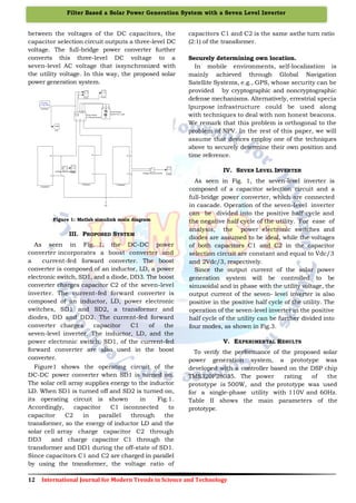
Figure 2:Voltage and current waveforms without LC filter
Figure 3:THD analysis 19.44% without LC filter
Figure 4:Voltage and current waveform using LC filter
Figure 5:THD analysis 5.56% with LC filter
VI. CONCLUSION
This paper proposes a solar power generation
system to convert the DC energy generated by a
solar cell array into AC energy that is fed into the
utility. The proposed solar power generation
system is composed of a DC/DC power converter
and a seven-level inverter. The seven-level inverter
contains only six power electronic switches, which
simplifies the circuit configuration. Furthermore,
only one power electronic switch is switched at
high frequency at any time to generate the
seven-level output voltage. This reduces the
switching power loss and improves the power
efficiency. The voltages of the two DC capacitors in
the proposed sevenlevel inverter are balanced
automatically, so the control circuit is simplified.
Experimental results show that the proposed solar
power generation system generates a sevenlevel
output voltage and outputs a sinusoidal current
that is in phase with the utility voltage, yielding a
power factor of unity. In addition, the proposed
solar power generation system can effectively trace
the maximum power of solar cell array
onclusion section is not required. Although a
conclusion may review the main points of the
paper, do not replicate the abstract as the
conclusion. A conclusion might elaborate on the
importance of the work or suggest applications and
extensions.
REFERENCES
[1] R.A. Mastromauro, M. Liserre, A.Dell'Aquila,
“Control Issues in Single-Stage Photovoltaic
Systems: MPPT, Current and Voltage Control,” IEEE
Trans Ind. Informat., Vol. 8, No.2, pp.241-254, 2012.
0 0.2 0.4 0.6 0.8 1
-400
-200
0
200
400
Selected signal: 50 cycles. FFT window (in red): 2 cycles
Time (s)
0 200 400 600 800 1000
0
0.5
1
1.5
2
Frequency (Hz)
Fundamental (50Hz) = 386 , THD= 5.56%
Mag(%ofFundamental)](https://image.slidesharecdn.com/39-160517111641/85/Filter-Based-Solar-Power-Generation-System-with-a-Seven-Level-Inverter-3-320.jpg)
![14 International Journal for Modern Trends in Science and Technology
Filter Based a Solar Power Generation System with a Seven Level Inverter
[2] Z. Zhao, M. Xu, Q. Chen, J.S Jason Lai, Y. H. Cho,
“Derivation, Analysis, and Implementation of a
Boost-Buck Converter-Based High-Efficiency PV
Inverter,” IEEE Trans. Power Electron., Vol. 27, No. 3,
pp.1304-1313, 2012.
[3] M. Hanif, M. Basu, K. Gaughan., “Understanding
the operation of a Z-source inverter for photovoltaic
application with a design example,” IET Power
Electron., Vol. 4, No. 3, pp.278-287, 2011.
[4] J, M. Shen, H. L. Jou, J. C. Wu, “Novel
Transformer-less Grid-connected Power Converter
with Negative Grounding for Photovoltaic Generation
System,” IEEE Trans. Power Electronics, Vol. 27, No.
4, pp.1818-1829, 2012.
[5] N. Mohan, T. M. Undeland, W. P. Robbins, Power
Electronics Converters, Applications and Design,
Media Enhanced 3rd ed. New York: John Wiely&
Sons, 2003.
[6] K. Hasegawa, H. Akagi, “Low-Modulation-Index
Operation of a Five-Level Diode-Clamped PWM
Inverter With a DC-Voltage-Balancing Circuit for a
Motor Drive ,” IEEE Trans. Power Electron., Vol. 27,
No. 8, pp.3495-3505, 2012.
[7] E. Pouresmaeil, D. Montesinos-Miracle, O. Gomis-
Bellmunt, ”Control Scheme of Three-Level NPC
Inverter for Integration of Renewable Energy
Resources Into AC Grid,“ Syst. J., Vol.6, No.2,
pp.242-253, 2012.
[8] S. Srikanthan, M. K. Mishra, “DC Capacitor
Voltage Equalization in NeutralClamped Inverters for
DSTATCOM Application,” IEEE Trans. Ind.
Electron. Vol. 57, No.8, pp.2768-2775, 2010.
[9] M. Chaves, E. Margato, J. F. Silva, S. F. Pinto,
“New approach in back-to-back m-level
diodeclamped multilevel converter modelling and
direct current bus voltages balancing,” IET Power
Electron., Vol. 3, No. 4, pp. 578-589, 2010.
[10] J. D. Barros, J. F. A. Silva, E. G. A Jesus, “Fast-
Predictive Optimal Control of NPC Multilevel
Converters,” IEEE Trans. Ind. Electron., Vol.60, No.2,
pp.619-627, 2013.
[11]A.K. Sadigh, S. H. Hosseini, M. Sabahi, G. B.
Gharehpetian, “Double Flying Capacitor Multicell
Converter Based on Modified Phase-Shifted
Pulsewidth Modulation,” IEEE Trans. Power
Electron., Vol. 25, No.6, pp. 1517-1526, 2010.
[12]S. Thielemans, A. Ruderman, B. Reznikov, J.
Melkebeek, “Improved Natural Balancing With
Modified Phase-Shifted PWM for Single-Leg Five-
Level Flying-Capacitor Converters,” IEEE Trans.
Power Electron., Vol. 27, No. 4, pp. 1658-1667,
2012.
[13]S. Choi, M. Saeedifard, “Capacitor Voltage
Balancing of Flying Capacitor Multilevel
Converters by Space Vector PWM,” IEEE Trans.
Power Del., Vol.27, No.3, pp.1154-1161, 2012.
[14]L. Maharjan, T. Yamagishi, H. Akagi, "Active-
Power Control of Individual Converter Cells for a
Battery Energy Storage System Based on a
Multilevel Cascade PWM Converter,” IEEE
Trans. Power Electron., Vol. 27, No.3,
pp.1099-1107, 2012.
[15]X. She, A. Q. Huang, T. Zhao; G. Wang,
“Coupling Effect Reduction of a Voltage-Balancing
Controller in Single-Phase Cascaded Multilevel
Converters,”.](https://image.slidesharecdn.com/39-160517111641/85/Filter-Based-Solar-Power-Generation-System-with-a-Seven-Level-Inverter-4-320.jpg)

This paper presents a novel solar power generation system utilizing a dc/dc power converter and a seven-level inverter, designed to efficiently convert dc energy from solar cells into ac energy for utility integration. The system employs a capacitor selection circuit and a full-bridge power converter, allowing for a simplified circuit configuration and enhanced power efficiency with minimal switching loss. Experimental results confirm that the system successfully generates a sinusoidal output current in phase with the utility voltage, achieving a power factor of unity.