Download to read offline
![International Journal of Research in Engineering and Science (IJRES)
ISSN (Online): 2320-9364, ISSN (Print): 2320-9356
www.ijres.org Volume 2 Issue 3 ǁ March. 2013 ǁ PP.01-05
www.ijres.org 1 | Page
High Proficiency Grid ConnectedPhotovoltaic Power Generation
System
MariarajaP1
, BrindhaSakthiB2
,Saranya A V3
1
Assistant Professor, Department of PG-ES, P.A.College of Engineering and Technology
2&3
PG student,P.A.College of Engineering and Technology
Abstract:Solar energy hasbecomepopular nowadays and desire for clean energy. Since the solar radiation on no
occasion remains constant,it keeps on insecure throughout the day. The need of the hour is to distribute a
constant voltage to the grid irrespective of the deviation in temperatures and solar insolation. The inverter is
designed from a boost converter along with a line frequency. The voltage from the boost converter is fedto the
grid through inverter. In this proposed method high efficiency can be achievedby using only one switch
functioning at high frequency at a time. The converter uses IGBT and ultra-fast reverse recovery diode. The
simulation and experiment results are verified using MATLAB/Simulink software.
Index terms:PV cells, Renewable Energy, DC–DCConverters, Inverters
I. INTRODUCTION
Now a day’s Photovoltaic power gaining more attention in supplying power to grid. Number of inverter
and control schemes is used in photovoltaic applications.Single phase utility inverters are used for residential
PV power generation systems. This type of residential application requires a power level lower than 5 kWand a
high input voltage stack that provides a dc voltage about 400V [2]. Based on the PV panel characteristics and
due to irradiation conditions, temperature variations and clouding effects the output DC voltage varies.
Therefore, residential PV inverter input voltage can vary widely. For example, from 300 to 500V, and can be
quite different from the desirable 400-V level. Thus, step up function, step down function or even both step up
and step down function with DC-DC converter is needed before an inverter stage. Such a dc–dc converter in
conjunction with a dc–ac inverter arrangement has been widely used in thePV. This PV based power is widely
used in grid connected system [7]-[8]. PV offers more advantages like freely available source, pollution free and
most abundant source.Figure. 1 shows the block diagram of the PV PCS. This method consists of two stage
power conversion with high frequency in cascaded configuration. It also consists of DC link in the middle.
Figure 1: Conventional two-stage PV
In this arrangement, the dc-bus voltage from the PV arrayshould be boosted, and the voltage-source-
type high-frequency inverter can be a dc–ac stage. Aline commutated inverter along with isolated dc-dc stage
can also be used [1].
II. PROPOSED HIGH EFFICIENCY BOOST CONVERTER BASED PV INVERTER
Photovoltaic (PV) is a method that uses semiconductors to generate electric power by solar
radiation, that exhibit the photovoltaic effect. Photovoltaic power generation employs solar panels composed of
a number of solar cells containing a photovoltaic material. Materials presently used for photovoltaic
include monocrystalline silicon, polycrystalline silicon, amorphous silicon, cadmium telluride, and copper
indium gallium selenide/sulphide [4]-[6]. Due to the increased demand for renewable energy sources, the
manufacturing of solar cells and photovoltaic arrays has advanced considerably in recent years.
In this chapter, the state-of-the-art single stage PV inverters are reviewed firstly. For these single stage
PV inverters either a transformer is used for boosting the input voltage or the input voltage will be required to be
higher than the peak of the grid voltage which is not good for PV application because the PV panel's
characteristics changes all the time. The energy storage needs to be at the front of a single stage inverter, and it
is usually implemented by electrolytic capacitors [3]. The lifetime issue of an electrolytic capacitor is](https://image.slidesharecdn.com/a0230105-150115010749-conversion-gate02/85/High-Proficiency-Grid-ConnectedPhotovoltaic-Power-Generation-System-1-320.jpg)
![International Journal of Research in Engineering and Science (IJRES)
ISSN (Online): 2320-9364, ISSN (Print): 2320-9356
www.ijres.org Volume 2 Issue 3 ǁ March. 2013 ǁ PP.01-05
www.ijres.org 1 | Page
High Proficiency Grid ConnectedPhotovoltaic Power Generation
System
MariarajaP1
, BrindhaSakthiB2
,Saranya A V3
1
Assistant Professor, Department of PG-ES, P.A.College of Engineering and Technology
2&3
PG student,P.A.College of Engineering and Technology
Abstract:Solar energy hasbecomepopular nowadays and desire for clean energy. Since the solar radiation on no
occasion remains constant,it keeps on insecure throughout the day. The need of the hour is to distribute a
constant voltage to the grid irrespective of the deviation in temperatures and solar insolation. The inverter is
designed from a boost converter along with a line frequency. The voltage from the boost converter is fedto the
grid through inverter. In this proposed method high efficiency can be achievedby using only one switch
functioning at high frequency at a time. The converter uses IGBT and ultra-fast reverse recovery diode. The
simulation and experiment results are verified using MATLAB/Simulink software.
Index terms:PV cells, Renewable Energy, DC–DCConverters, Inverters
I. INTRODUCTION
Now a day’s Photovoltaic power gaining more attention in supplying power to grid. Number of inverter
and control schemes is used in photovoltaic applications.Single phase utility inverters are used for residential
PV power generation systems. This type of residential application requires a power level lower than 5 kWand a
high input voltage stack that provides a dc voltage about 400V [2]. Based on the PV panel characteristics and
due to irradiation conditions, temperature variations and clouding effects the output DC voltage varies.
Therefore, residential PV inverter input voltage can vary widely. For example, from 300 to 500V, and can be
quite different from the desirable 400-V level. Thus, step up function, step down function or even both step up
and step down function with DC-DC converter is needed before an inverter stage. Such a dc–dc converter in
conjunction with a dc–ac inverter arrangement has been widely used in thePV. This PV based power is widely
used in grid connected system [7]-[8]. PV offers more advantages like freely available source, pollution free and
most abundant source.Figure. 1 shows the block diagram of the PV PCS. This method consists of two stage
power conversion with high frequency in cascaded configuration. It also consists of DC link in the middle.
Figure 1: Conventional two-stage PV
In this arrangement, the dc-bus voltage from the PV arrayshould be boosted, and the voltage-source-
type high-frequency inverter can be a dc–ac stage. Aline commutated inverter along with isolated dc-dc stage
can also be used [1].
II. PROPOSED HIGH EFFICIENCY BOOST CONVERTER BASED PV INVERTER
Photovoltaic (PV) is a method that uses semiconductors to generate electric power by solar
radiation, that exhibit the photovoltaic effect. Photovoltaic power generation employs solar panels composed of
a number of solar cells containing a photovoltaic material. Materials presently used for photovoltaic
include monocrystalline silicon, polycrystalline silicon, amorphous silicon, cadmium telluride, and copper
indium gallium selenide/sulphide [4]-[6]. Due to the increased demand for renewable energy sources, the
manufacturing of solar cells and photovoltaic arrays has advanced considerably in recent years.
In this chapter, the state-of-the-art single stage PV inverters are reviewed firstly. For these single stage
PV inverters either a transformer is used for boosting the input voltage or the input voltage will be required to be
higher than the peak of the grid voltage which is not good for PV application because the PV panel's
characteristics changes all the time. The energy storage needs to be at the front of a single stage inverter, and it
is usually implemented by electrolytic capacitors [3]. The lifetime issue of an electrolytic capacitor is](https://image.slidesharecdn.com/a0230105-150115010749-conversion-gate02/75/High-Proficiency-Grid-ConnectedPhotovoltaic-Power-Generation-System-1-2048.jpg)
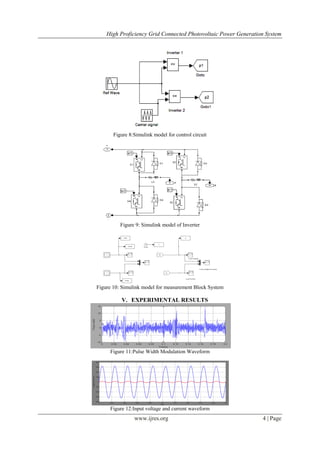
![High Proficiency Grid Connected Photovoltaic Power Generation System
www.ijres.org 3 | Page
Figure 4: Simulink model for Photo Voltaic
This converter converts the signal from AC to Dc signal. The sub block system is available for boost
converter. MOSFET is used as a switch in a Boost converter. Gate signal is given to the switch through closed
loop.
Figure 5: Simulink model Boost chopper with inverter
Figure 6: Simulink model of Electrical grid
Figure 7: Simulink model of Boost converter model
The Electrical grid model is shown in the figure 6 [9]-[10]. The Boost converter controller model is
shown in the figure 7. PI controller is used to extract the boost converter model. The boost converter with
proposed controller gives faster response to meet the desired output.](https://image.slidesharecdn.com/a0230105-150115010749-conversion-gate02/85/High-Proficiency-Grid-ConnectedPhotovoltaic-Power-Generation-System-3-320.jpg)
![High Proficiency Grid Connected Photovoltaic Power Generation System
www.ijres.org 5 | Page
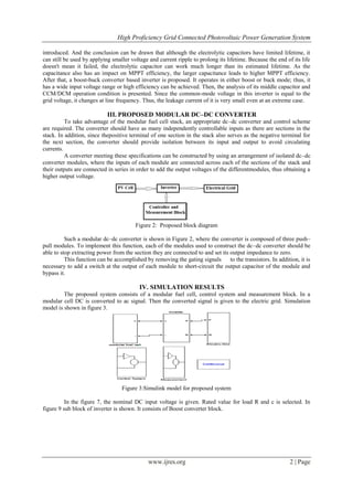
Figure 13:Load voltage and current waveform
VI. Conclusion
In this paper, a PV cell and dc–dc converter concept with inverter has been presented. Due to time
constraints, MPPT algorithm is not used in boost converter.The proposed system has been shown to be fault
tolerant and can continue to operate at a reduced power level under power module faults. The proposed system
is capable of producing 10% additional power when compared to the traditional approach. In addition,
experimental results also confirm the operation of the system under stackfailure.
REFERENCE
[1] F.Blaabjerg,Z.Chen and S.Kjer,”Power electronics as efficientinterfacein dispersed power generation systems.
[2] H. Hwang, K. S. Ahn, H. C. Lim, S. S. Kim. Design, development and performance of a 50kW grid connected PV system with
three phase current-controlled inverter. In: Photovoltaic Specialists Conference, Conference Record of the 28th IEEE, pp. 1664-
1667, 2000.
[3] C. Cecati, A. Dell'Aquila, M. Liserre. “A novel three-phase single-stage distributed power inverter”. IEEE Transactions on
Power Electronics, vol. 19, Issue 5, pp.1226-1233, 2004.
[4] T.B. Johansson, H. Kelly, A.K.N. Reddy and R.H. Williams: Renewable Energy - Sources for fuels and electricity. Island Press,
1993.
[5] J. Twidell and T. Weir: Renewable Energy Resources. E & F.N. Spon, 1990.
[6] W. Hulscher and P. Fraenkel: The Power Guide - An international catalogue of small-scale energy equipment. ITDG Publishing,
1994.
[7] Derrick, C. Francis and V. Bokalders: Solar Photovoltaic Products - A guide for development workers. IT Publications and IT
Power, 1991.
[8] S. Roberts: Solar Electricity - A practical guide to designing and installing photovoltaic systems. Prentice Hall, 1991.
[9] Carletti, R.L., Lopes, C.G., Barbosa, P.G., 2005. Active & reactive power control scheme for a grid-connected photovoltaic
generation system based on VSI with selective harmonic eliminations. In: 8th
Power Electronics Brazilian Conference, COBEP,
Recife, pp. 129-134.
[10] J.Carrasco,L.Franquelo,J.Bbialasiewicz,E.Galvan,R.Portiloguisado,”Power electronics for system for grid integration of
renewable energy sources.
[11] IEEE Standard for interconnecting distributed sources with electric power systems.
[12] H.P. Garg, D. Gouri, and R. Gupta: Renewable Energy Technologies. Indian Institute of technology and the British High
Commission, 1997.
[13] S. Karekezi and T. Ranja: Renewable Energy Technologies in Africa. AFREPREN/SEI/Zed Books, 1997.
BIOGRAPHY
P.Mariaraja He received his B.E in Electrical and Electronics Engineering from PSG College of Technology,
Coimbatore, in 2004 and M.E degree in Power Electronics and Drives from AnnaiMathammalSheela
Engineering College, Nammakal, in 2011. He is currently Assistant Professor of PG-Electrical Sciences at
P.A.College of Engineering and Technology, Pollachi, Coimbatore. His research interests are in the field of
electrical power Systems simulation and fault analysis.
B BrindhaSakthiShe received her B.E (Electrical and Electronics Engineering) degree from Maharaja
Engineering College, Coimbatore, in 2011, and pursuing M.E., (Power Electronics and Drives) degree in P.A
College of Engineering and Technology, Pollachi. She is now working on her project regarding allocation of
FACTS devices in transmission lines to minimize the loss.
A V SaranyaShe received her B.E (Electrical and Electronics Engineering) degree from KalaignarKarunanidhi
Institute of Technology Coimbatore, in 2012, and pursuing M.E., (Power Electronics and Drives) degree in P.A
College of Engineering and Technology, Pollachi. She is now working on her project regarding location of
FACTS devices in transmission lines using optimization technique.](https://image.slidesharecdn.com/a0230105-150115010749-conversion-gate02/85/High-Proficiency-Grid-ConnectedPhotovoltaic-Power-Generation-System-5-320.jpg)

The document discusses a high proficiency grid-connected photovoltaic power generation system, emphasizing the importance of maintaining a constant voltage to the electrical grid despite variations in solar radiation. It proposes an inverter design using a boost converter to improve efficiency while documenting the system's simulation results through MATLAB/Simulink software. The findings indicate that the proposed system can deliver 10% more power compared to traditional methods and can operate under certain fault conditions.