The document outlines a simulation project on photonics focused on tracking design parameters of step-index fiber optics, specifically single mode fibers (SMF) and multimode fibers (MMF). The simulation examines how variations in core and cladding diameters and wavelengths affect fiber types, utilizing boundary conditions and a specified wavelength range. It concludes that core diameter is crucial in distinguishing between SMF and MMF and identifies a cutoff normalized frequency that helps in this determination.

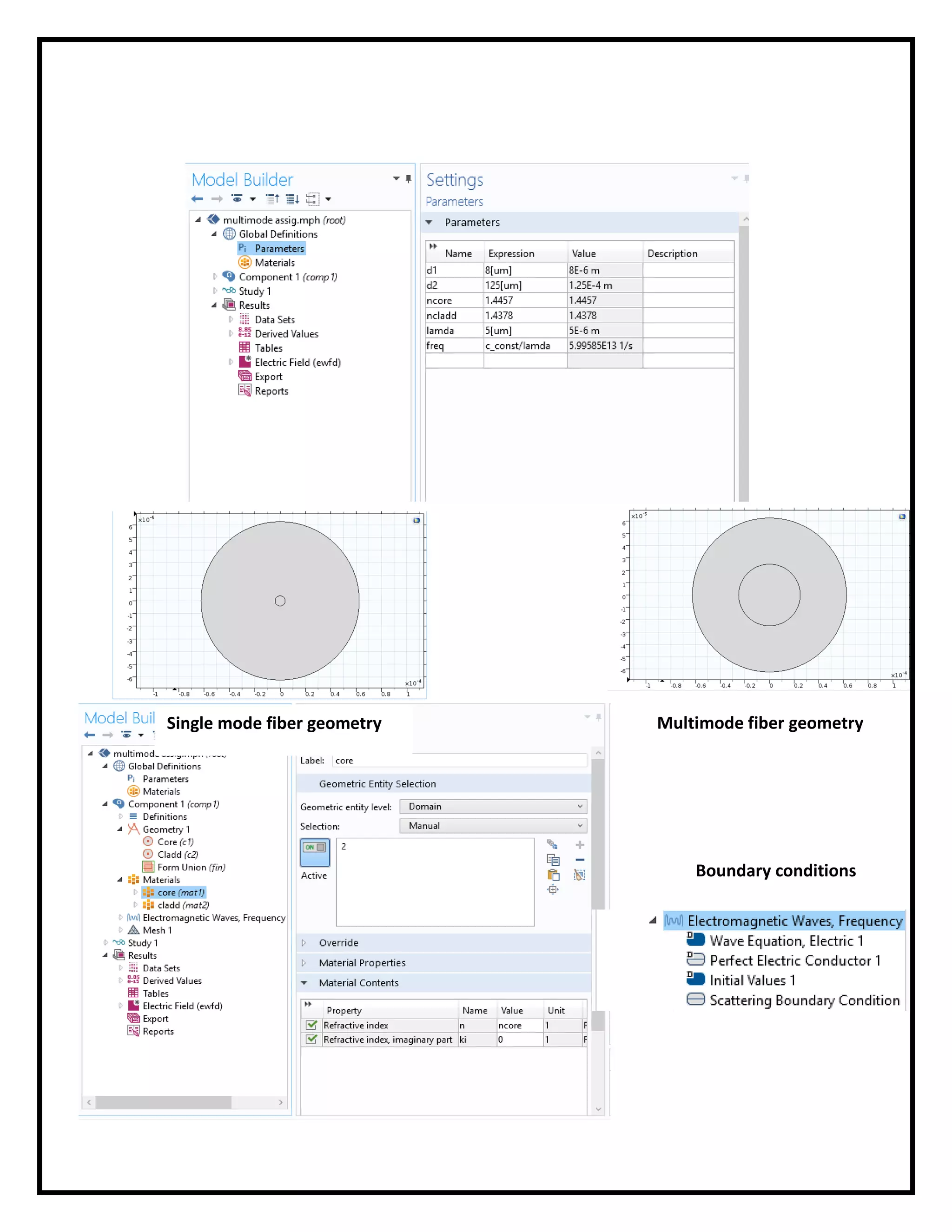
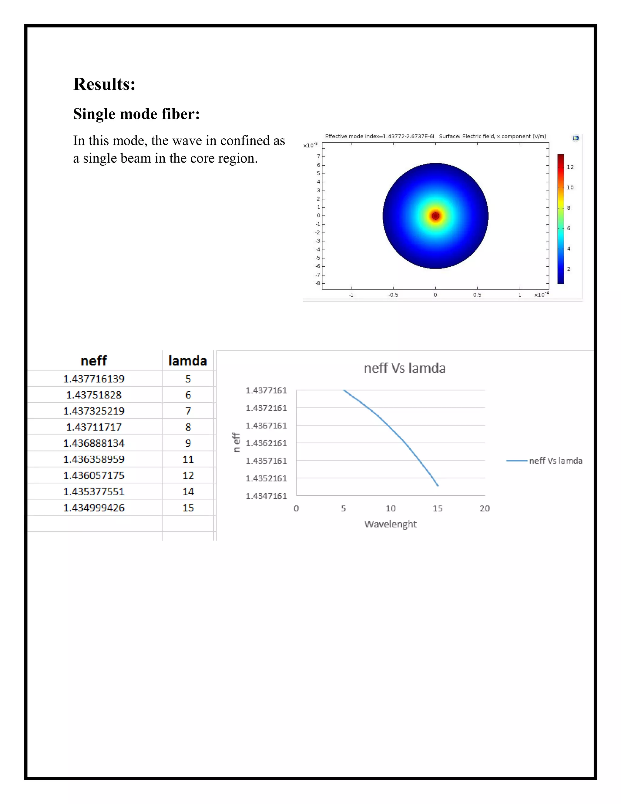
![ The simulation will be applied through a wavelength range [5:15] *10^-6 m
in both (SMF) and (MMF).
The core material has refractive index of 1.4457 and the clad material has
refractive index of 1.4378 (Ncore > Nclad ).
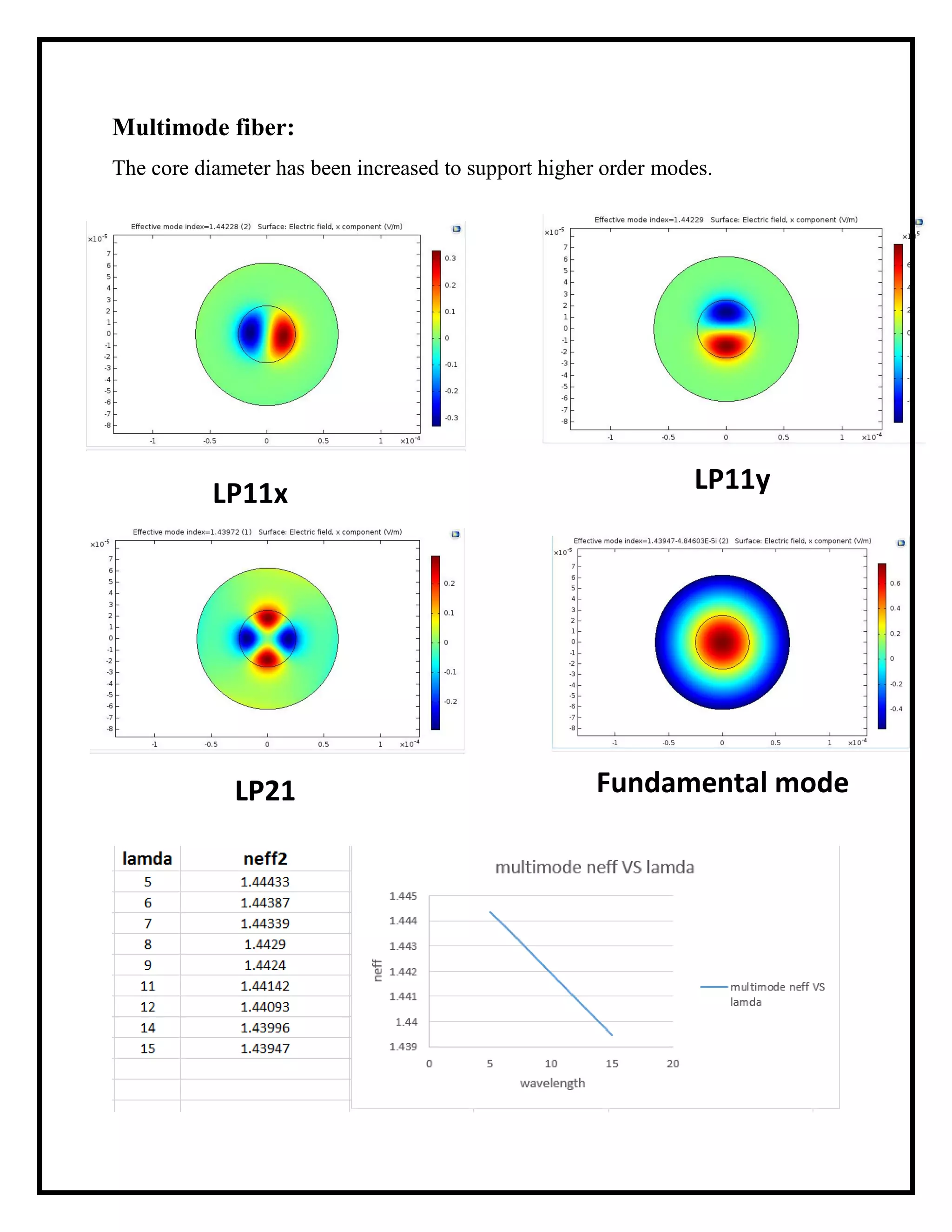
The meshing has been increased in the core region; as modes concerned are
within the core region.
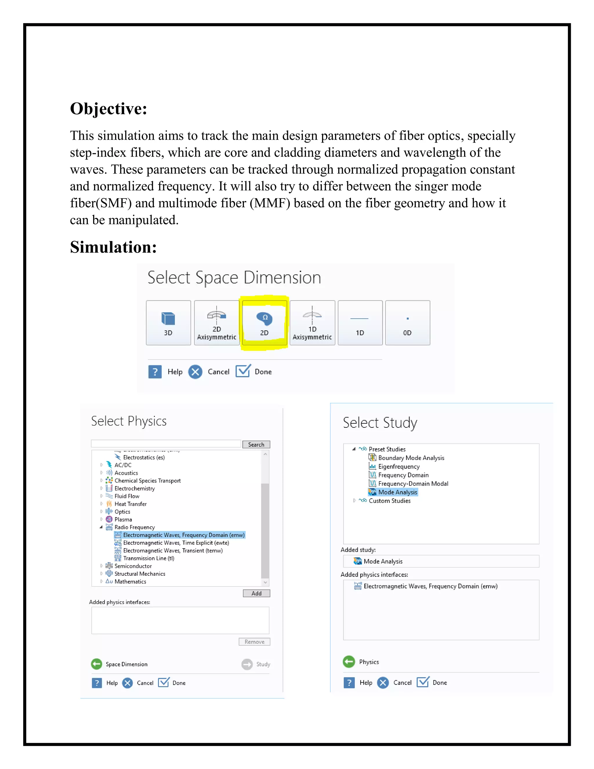
Scattering boundary condition has been used to prevent the escape on the
waves from the clad.
Mesh Applied](https://image.slidesharecdn.com/fiberopricsreport-170404125048/75/Fiber-optics-project-report-4-2048.jpg)