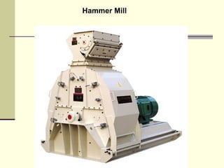
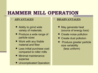
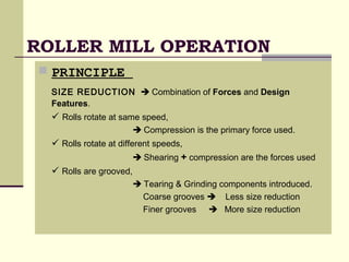
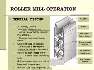
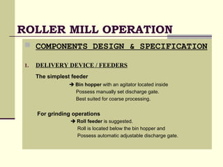
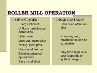
````
Feed ManufacturingFeed Manufacturing
Process Flow Diagram
Receiving
Grinding
Mixing
Processing
Premixing
Liquid receiving
& Storage
Packaging
Ware House
Bulk Loadout
FEED MANUFACTURINGFEED MANUFACTURING
 Screening
 Particle Size
 Computerize Batching
 Mixing & Mixibility
 Mash & Pellet
GrindingGrinding
Why Do We GrindWhy Do We Grind
 Expose greater surface area for digestion.
 Improve mixing characteristics of ingredients.
 Improve the potential for further processing.
 Satisfying customer preferences
GRINDING
 DEFINITION:
 The particle size reduction
which increases both
 The number of particles
 The amount of surface area
per unit of volume
 Also modify the physical
characteristics of ingredients
  Access to nutritional comp. as
 starch & Protein

  Grain Interior is exposed to
digestive enzymes

 Enhanced breakdown improves
absorption in the digestive tract.
    
  ANIMAL PERFORMANCE
  Mixing
  Conditioning
  Pellet Quality
  Pelleting efficiency
  Feed handling & transport.
GRINDING
 MATERIALS
 Majority of materials either
 Within the feed plant or
 Prior to receiving.
 Most Common are
 Grains
 Corn
 Sorghum
 Wheat
 Meals
 Canola meal
 Soybean meal
GRINDING
 PARTICLE SIZE
 In past, Terms used were
 Fine
 Medium
 Coarse
 Thus
 Standard procedure
1) Series of sieves are used
2) Grain Amount Retained on
Each sieve analyzed
3) Mathematical calculation /
Formula is applied
 Particle size uniformity in
a particular sample
 These are relative terms
 Little use in evaluating
research on the particle size
GMD
(Geometric Mean Diameter)
Measured in Microns “μ”
GSD
(Geometric Standard Deviation)
 GSD   uniformity
 GSD   uniformity
PARTICLE SIZE
 Particle size of ground material by hammer mill
Using different screens
S. #
Screen Size GMD
Category
Inches mm μ (range)
1 1/8 3.18 540—630 Finer
2 3/16 4.76 680—720 Fine
3 1/4 6.35 720—880 Medium
4 ? 7.94 About 970 Coarse
5 ? 9.59 About 1200 Coarser
PARTICLE SIZE
 EFFECT ON PELLET DURABILITY
 The accepted principles
1. A finer grind results in a more durable pellet.
2. Fine or medium ground materials

 Surface area for moisture absorption from steam

better lubrication and increased production rates.
3. Very coarse grinds or large particle size

provide natural breaking points in pellets

Creating more fines, lowering pellet quality.
PARTICLE SIZE
 EFFECT ON NUTRIENT COMPOSITION
CORN  Different fractions based on Particle Size

have little or no effect on nutrient composition. [ Nir et al. 1994 ]
 CONCLUSIONS
 In pelleted or crumbled diets
little effect on live performance,
uniformity of nutrient content of feed
Or the pellet quality produced
 If grains are to be incorporated into mash,
Finer particle sizes (less than 600 µ GMD) should be avoided.
 Producers should adjust grinding size depending the form of diet to
be fed ( Mash / Pellet) using hammer mill and roller mill grinding.
GRINDING
 METHODS FOR PARTICLE SIZE REDUCTION
 HAMMER MILL OPERATION
 ROLLER MILL OPERATION
Principle
General design
Components design & specification
Functional Advantages & Disadvantages
Hammer MillHammer Mill
 Most common grinding device
 Versatile and efficient
 Half circle, full circle, tear top, fixed hammer,
free to swing, fixed impact bars.
Hammer Mill
HAMMER MILL OPERATION
 GENERAL DESIGN
1) A delivery device
(For material introduction)
2) Rotor Assembly
With series of disks
Mounted on the
horizontal shaft
3) Free-swinging hammers
Suspended from rods
4) Perforated screen
5) Removal of ground product
Either gravity- or Air-assisted
Horizontal
shaft
HAMMER MILL OPERATION
Hammers
Rotor Plates
Rod
Rotor Shaft
Rotor
Assembly
Outlet &
Take Away
Air Assist
Motor
Screen
Inlet
HAMMER MILL INTERIOR
The Grinding Theory
Hammers
Rod
Rotor Shaft
Outlet
Motor
& Belt
Screen
Grinding
Zone
HAMMER MILL FUNCTIONING
Inlet
System Design Factors
 Feed material characteristics
 Size (decide multistep grinding or single)
 Moisture contents (determine dust collector)
 Grindability (hardness, density etc..)
 Temperature sensitivity
 Hammer mill factors
 Operating requirements (capacity, horsepower,
hammer-tip speed)
 Safety requirements (magnets, exploisable, sensors )
 Contamination and Cleaning Requirements
 Space Requirements
 Maintenance Requirements
 Related equipments
 Feeders
 Drives
 Sensor Monitoring
System Design Factors
HAMMER MILL OPERATION
 VARIABLES
a) # Of Hammers on shaft
b) Size of Hammers used
c) Arrangement manipulated
d) The hammer Sharpness
e) Hammer Wear patterns
f) Hammer-tip speed
g) Screen design
h) Screen hole size
i) Whether or not air assist is used.

GRINDING CAPACITY
APPEARANCE OF THE PRODUCT
4.06
2.84
1.63
0.85
0
1
2
3
4
5
Prod.
Rate
T/H
900 700 500 300
Partile size (Mirons)
Particle size &
Rate of Production
HAMMER MILL OPERATION
 COMPONENTS DESIGN & SPECIFICATION
1. DELIVERY DEVICE / FEEDERS
 Screw feeders,
 Rotary vane pocket feeders,
 Vibratory feeders,
 Belt feeders,
 Drag feeders,
 "Pocket" feeder, Fitted with a Rotor
Considerations For Feeder Selection
 Initial cost,
 Evenness of feed,
 Compatibility with product
 Physical size of the feeder,
 The estimated maintenance cost
Screw Feeder
Rotary vane pocket feeders
COMPONENTS DESIGN & SPEC.
2. HAMMER DESIGN
 Optimal hammer design  Maximum contact with the feed ingredient.
SIZE:
Rotor speed = 1,800 rpm, 10 In. Long, 2.5 In. Across & 0.25 In Thick
Rotor speed = 3,600 rpm, 6 to 8 In Long, 2 In Across, & 0.25 In Thick
NUMBER:
For 1,800 rpm = 1 for every 2.5 to 3.5 Horsepower
For 3,600 rpm = 1 for every 1 to 2 Horsepower
DISTANCE:
The distance b/w hammer & screen = 0.5 In For cereal grains.
HAMMER TIP SPEED:
Tip speed of the hammers is critical for proper size reduction
Tip speeds commonly Range Between 16,000b & 23,000 F/ M
COMPONENTS DESIGN & SPEC.
3. SCREEN DESIGN:
 Open area of screen Determines
The particle size &
Grinding efficiency.
DESIGN
Designed to maintain
The Integrity & Greatest amount of open area
Generally
Screen openings (holes)  aligned in a 60-dig. Staggered pattern
 This method will result in a 40 percent open area
 Optimized open area while maintaining screen strength
OPEN SCREEN AREA TO HORSEPOWER.
 Recommended ratio for grains = 8 to 9 square Inch per Horsepower.
 Not enough open Area / Horsepower  generation of heat.
 Generated Heat Exceeds 120F to 125F (44C to 46C)

Capacity may be decreased as much as 50 percent.
COMPONENTS DESIGN & SPEC.
4. GROUND MATERIAL REMOVAL
 A critical design feature
 Directly affects the efficiency of operation
 Also affects the particle size determination
AIR ASSIST SYSTEM
 Most newer hammermills are equipped
 Draws air into the hammermill with the product to be ground.
 Provide Reduced pressure on exit side of the screen
 Disrupt the fluidized bed of material on the face of the screen

Allow particles to exit easily through screen holes.
HAMMER MILL OPERATION
 ADVANTAGES
 Ability to grind wide
variety of materials.
 Produce a wide range of
particle sizes
 Work with any friable
material and fiber
 Less initial purchase cost
compared to roller mills
 Minimal maintenance
expense
 Uncomplicated Operation
 DISADVANTAGES
 May generate heat
(source of energy loss)
 Create noise pollution
 Create dust pollution
 Produce greater particle
size variability
(less uniform)
ROLLER MILL OPERATION
 PRINCIPLE
SIZE REDUCTION  Combination of Forces and Design
Features.
 Rolls rotate at same speed,
 Compression is the primary force used.
 Rolls rotate at different speeds,
 Shearing + compression are the forces used
 Rolls are grooved,
 Tearing & Grinding components introduced.
Coarse grooves  Less size reduction
Finer grooves  More size reduction
ROLLER MILL OPERATION
 GENERAL DESIGN
1) A Delivery Device
To supply a constant and
uniform amount of the material
2) Pair Of Rolls
Mounted horizontally in rigid
frame
3) One roll Fixed in position
And Other is Moveable
closer to or further from fixed roll
4) Rolls counter rotate either
at same speed or one may
faster
5) Roll surface may be smooth or
have various grooves
6) Pairs of rolls may be placed on
Rotor
1st
Roll Pair
Coarse Grooves
Coarse ground
Material
Inlet Bin
2nd
Roll Pair
Fine Grooves
Fine Ground
Material
ROLLER MILL OPERATION
 COMPONENTS DESIGN & SPECIFICATION
1. DELIVERY DEVICE / FEEDERS
The simplest feeder
 Bin hopper with an agitator located inside
Possess manually set discharge gate.
Best suited for coarse processing.
For grinding operations
 Roll feeder is suggested.
Roll is located below the bin hopper and
Possess automatic adjustable discharge gate.
COMPONENTS DESIGN & SPEC
2. ROLL SPECIFICATIONS
IN A PAIR
Rolls are 9 to 12 inches in diameter
Ratio of length to diameter can be as great as 4:1.
ALIGNMENT
Sizing dependent gap between the rolls along their length
Non Uniform gap  Increased maintenance costs & reduced out put,
 Overall increased operation costs.
Gap Adjusted automatically
Through pneumatic or hydraulic cylinders operated by programmable controller
COUNTER ROTATING SPEED
Typical differentials range from 1.2:1 to 2.0:1 (fast to slow)
Typical roll speeds would be 1,300 feet per minute for a 9-inch to
3,140 feet per minute for a 12-inch roll.
ROTATING MOTOR
Single motor is used to power a two roll pair
With either belt or chain reduction supplying the differential.
ROLLER MILL OPERATION
 ADVANTAGES
 Energy efficient
 Uniform particle-size
distribution
 Little noise
 Less dust generation
 No Sig. Heat prod.
 Decreased fire risk
 Excellent physical
appearance
 Easy installation
 DISADVANTAGES
 Little or no effect on
fiber
 when required,
maintenance can be
expensive
 may have high initial
cost (depends on
system design)
For coarse reduction of grain, a roller mill may have a
significant advantage over a hammermill in terms of
throughput/kwh of energy. For cereal grains processed to
typical sizes (600 to 900 microns) for the feed industry, the
advantage is about 30 to 50 percent. This translates into
reduced operating expense.
Feed manufacturing grinding

Feed manufacturing grinding

  • 1.
  • 2.
    Process Flow Diagram Receiving Grinding Mixing Processing Premixing Liquidreceiving & Storage Packaging Ware House Bulk Loadout
  • 3.
    FEED MANUFACTURINGFEED MANUFACTURING Screening  Particle Size  Computerize Batching  Mixing & Mixibility  Mash & Pellet
  • 4.
  • 5.
    Why Do WeGrindWhy Do We Grind  Expose greater surface area for digestion.  Improve mixing characteristics of ingredients.  Improve the potential for further processing.  Satisfying customer preferences
  • 6.
    GRINDING  DEFINITION:  Theparticle size reduction which increases both  The number of particles  The amount of surface area per unit of volume  Also modify the physical characteristics of ingredients   Access to nutritional comp. as  starch & Protein    Grain Interior is exposed to digestive enzymes   Enhanced breakdown improves absorption in the digestive tract.        ANIMAL PERFORMANCE   Mixing   Conditioning   Pellet Quality   Pelleting efficiency   Feed handling & transport.
  • 7.
    GRINDING  MATERIALS  Majorityof materials either  Within the feed plant or  Prior to receiving.  Most Common are  Grains  Corn  Sorghum  Wheat  Meals  Canola meal  Soybean meal
  • 8.
    GRINDING  PARTICLE SIZE In past, Terms used were  Fine  Medium  Coarse  Thus  Standard procedure 1) Series of sieves are used 2) Grain Amount Retained on Each sieve analyzed 3) Mathematical calculation / Formula is applied  Particle size uniformity in a particular sample  These are relative terms  Little use in evaluating research on the particle size GMD (Geometric Mean Diameter) Measured in Microns “μ” GSD (Geometric Standard Deviation)  GSD   uniformity  GSD   uniformity
  • 9.
    PARTICLE SIZE  Particlesize of ground material by hammer mill Using different screens S. # Screen Size GMD Category Inches mm μ (range) 1 1/8 3.18 540—630 Finer 2 3/16 4.76 680—720 Fine 3 1/4 6.35 720—880 Medium 4 ? 7.94 About 970 Coarse 5 ? 9.59 About 1200 Coarser
  • 10.
    PARTICLE SIZE  EFFECTON PELLET DURABILITY  The accepted principles 1. A finer grind results in a more durable pellet. 2. Fine or medium ground materials   Surface area for moisture absorption from steam  better lubrication and increased production rates. 3. Very coarse grinds or large particle size  provide natural breaking points in pellets  Creating more fines, lowering pellet quality.
  • 11.
    PARTICLE SIZE  EFFECTON NUTRIENT COMPOSITION CORN  Different fractions based on Particle Size  have little or no effect on nutrient composition. [ Nir et al. 1994 ]  CONCLUSIONS  In pelleted or crumbled diets little effect on live performance, uniformity of nutrient content of feed Or the pellet quality produced  If grains are to be incorporated into mash, Finer particle sizes (less than 600 µ GMD) should be avoided.  Producers should adjust grinding size depending the form of diet to be fed ( Mash / Pellet) using hammer mill and roller mill grinding.
  • 12.
    GRINDING  METHODS FORPARTICLE SIZE REDUCTION  HAMMER MILL OPERATION  ROLLER MILL OPERATION Principle General design Components design & specification Functional Advantages & Disadvantages
  • 13.
    Hammer MillHammer Mill Most common grinding device  Versatile and efficient  Half circle, full circle, tear top, fixed hammer, free to swing, fixed impact bars.
  • 14.
  • 15.
    HAMMER MILL OPERATION GENERAL DESIGN 1) A delivery device (For material introduction) 2) Rotor Assembly With series of disks Mounted on the horizontal shaft 3) Free-swinging hammers Suspended from rods 4) Perforated screen 5) Removal of ground product Either gravity- or Air-assisted Horizontal shaft
  • 16.
    HAMMER MILL OPERATION Hammers RotorPlates Rod Rotor Shaft Rotor Assembly Outlet & Take Away Air Assist Motor Screen Inlet HAMMER MILL INTERIOR
  • 17.
    The Grinding Theory Hammers Rod RotorShaft Outlet Motor & Belt Screen Grinding Zone HAMMER MILL FUNCTIONING Inlet
  • 18.
    System Design Factors Feed material characteristics  Size (decide multistep grinding or single)  Moisture contents (determine dust collector)  Grindability (hardness, density etc..)  Temperature sensitivity  Hammer mill factors  Operating requirements (capacity, horsepower, hammer-tip speed)  Safety requirements (magnets, exploisable, sensors )
  • 19.
     Contamination andCleaning Requirements  Space Requirements  Maintenance Requirements  Related equipments  Feeders  Drives  Sensor Monitoring System Design Factors
  • 20.
    HAMMER MILL OPERATION VARIABLES a) # Of Hammers on shaft b) Size of Hammers used c) Arrangement manipulated d) The hammer Sharpness e) Hammer Wear patterns f) Hammer-tip speed g) Screen design h) Screen hole size i) Whether or not air assist is used.  GRINDING CAPACITY APPEARANCE OF THE PRODUCT 4.06 2.84 1.63 0.85 0 1 2 3 4 5 Prod. Rate T/H 900 700 500 300 Partile size (Mirons) Particle size & Rate of Production
  • 21.
    HAMMER MILL OPERATION COMPONENTS DESIGN & SPECIFICATION 1. DELIVERY DEVICE / FEEDERS  Screw feeders,  Rotary vane pocket feeders,  Vibratory feeders,  Belt feeders,  Drag feeders,  "Pocket" feeder, Fitted with a Rotor Considerations For Feeder Selection  Initial cost,  Evenness of feed,  Compatibility with product  Physical size of the feeder,  The estimated maintenance cost
  • 22.
  • 23.
    COMPONENTS DESIGN &SPEC. 2. HAMMER DESIGN  Optimal hammer design  Maximum contact with the feed ingredient. SIZE: Rotor speed = 1,800 rpm, 10 In. Long, 2.5 In. Across & 0.25 In Thick Rotor speed = 3,600 rpm, 6 to 8 In Long, 2 In Across, & 0.25 In Thick NUMBER: For 1,800 rpm = 1 for every 2.5 to 3.5 Horsepower For 3,600 rpm = 1 for every 1 to 2 Horsepower DISTANCE: The distance b/w hammer & screen = 0.5 In For cereal grains. HAMMER TIP SPEED: Tip speed of the hammers is critical for proper size reduction Tip speeds commonly Range Between 16,000b & 23,000 F/ M
  • 24.
    COMPONENTS DESIGN &SPEC. 3. SCREEN DESIGN:  Open area of screen Determines The particle size & Grinding efficiency. DESIGN Designed to maintain The Integrity & Greatest amount of open area Generally Screen openings (holes)  aligned in a 60-dig. Staggered pattern  This method will result in a 40 percent open area  Optimized open area while maintaining screen strength OPEN SCREEN AREA TO HORSEPOWER.  Recommended ratio for grains = 8 to 9 square Inch per Horsepower.  Not enough open Area / Horsepower  generation of heat.  Generated Heat Exceeds 120F to 125F (44C to 46C)  Capacity may be decreased as much as 50 percent.
  • 25.
    COMPONENTS DESIGN &SPEC. 4. GROUND MATERIAL REMOVAL  A critical design feature  Directly affects the efficiency of operation  Also affects the particle size determination AIR ASSIST SYSTEM  Most newer hammermills are equipped  Draws air into the hammermill with the product to be ground.  Provide Reduced pressure on exit side of the screen  Disrupt the fluidized bed of material on the face of the screen  Allow particles to exit easily through screen holes.
  • 26.
    HAMMER MILL OPERATION ADVANTAGES  Ability to grind wide variety of materials.  Produce a wide range of particle sizes  Work with any friable material and fiber  Less initial purchase cost compared to roller mills  Minimal maintenance expense  Uncomplicated Operation  DISADVANTAGES  May generate heat (source of energy loss)  Create noise pollution  Create dust pollution  Produce greater particle size variability (less uniform)
  • 27.
    ROLLER MILL OPERATION PRINCIPLE SIZE REDUCTION  Combination of Forces and Design Features.  Rolls rotate at same speed,  Compression is the primary force used.  Rolls rotate at different speeds,  Shearing + compression are the forces used  Rolls are grooved,  Tearing & Grinding components introduced. Coarse grooves  Less size reduction Finer grooves  More size reduction
  • 28.
    ROLLER MILL OPERATION GENERAL DESIGN 1) A Delivery Device To supply a constant and uniform amount of the material 2) Pair Of Rolls Mounted horizontally in rigid frame 3) One roll Fixed in position And Other is Moveable closer to or further from fixed roll 4) Rolls counter rotate either at same speed or one may faster 5) Roll surface may be smooth or have various grooves 6) Pairs of rolls may be placed on Rotor 1st Roll Pair Coarse Grooves Coarse ground Material Inlet Bin 2nd Roll Pair Fine Grooves Fine Ground Material
  • 29.
    ROLLER MILL OPERATION COMPONENTS DESIGN & SPECIFICATION 1. DELIVERY DEVICE / FEEDERS The simplest feeder  Bin hopper with an agitator located inside Possess manually set discharge gate. Best suited for coarse processing. For grinding operations  Roll feeder is suggested. Roll is located below the bin hopper and Possess automatic adjustable discharge gate.
  • 30.
    COMPONENTS DESIGN &SPEC 2. ROLL SPECIFICATIONS IN A PAIR Rolls are 9 to 12 inches in diameter Ratio of length to diameter can be as great as 4:1. ALIGNMENT Sizing dependent gap between the rolls along their length Non Uniform gap  Increased maintenance costs & reduced out put,  Overall increased operation costs. Gap Adjusted automatically Through pneumatic or hydraulic cylinders operated by programmable controller COUNTER ROTATING SPEED Typical differentials range from 1.2:1 to 2.0:1 (fast to slow) Typical roll speeds would be 1,300 feet per minute for a 9-inch to 3,140 feet per minute for a 12-inch roll. ROTATING MOTOR Single motor is used to power a two roll pair With either belt or chain reduction supplying the differential.
  • 31.
    ROLLER MILL OPERATION ADVANTAGES  Energy efficient  Uniform particle-size distribution  Little noise  Less dust generation  No Sig. Heat prod.  Decreased fire risk  Excellent physical appearance  Easy installation  DISADVANTAGES  Little or no effect on fiber  when required, maintenance can be expensive  may have high initial cost (depends on system design)
  • 32.
    For coarse reductionof grain, a roller mill may have a significant advantage over a hammermill in terms of throughput/kwh of energy. For cereal grains processed to typical sizes (600 to 900 microns) for the feed industry, the advantage is about 30 to 50 percent. This translates into reduced operating expense.