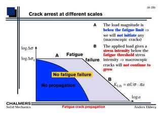
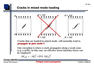
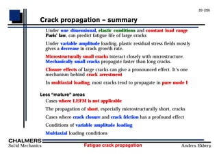
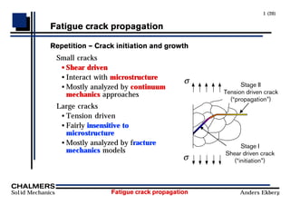
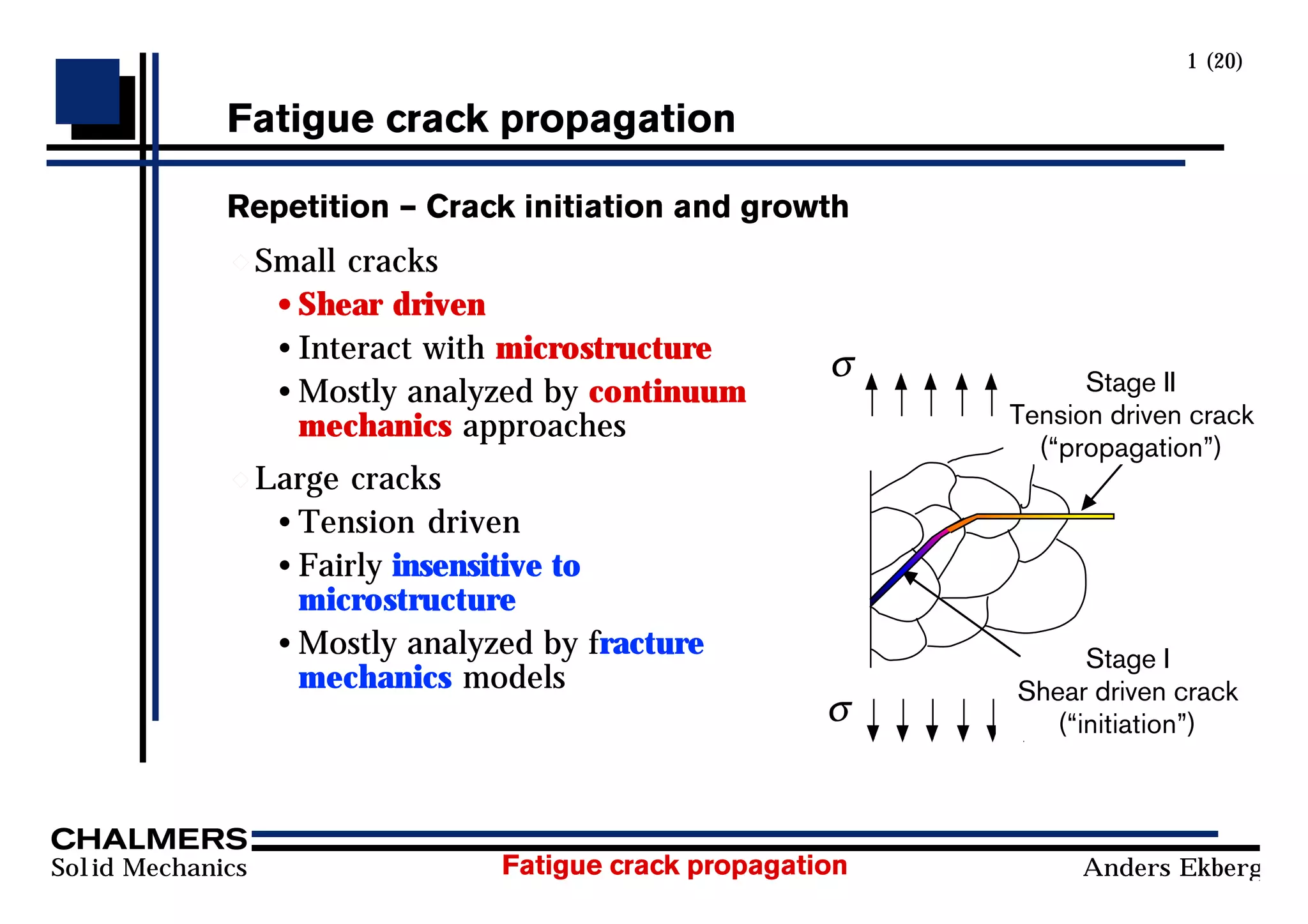
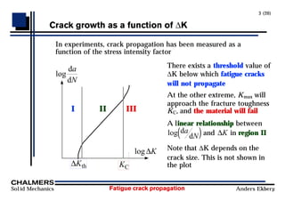
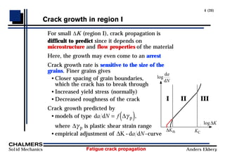
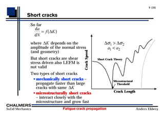
Fatigue crack propagation can be analyzed using continuum mechanics approaches and fracture mechanics models. Small cracks are driven by shear stresses and interact closely with microstructure, while large cracks are driven by tension and are less dependent on microstructure. Crack propagation rate depends on the stress intensity factor range (ΔK) and can be modeled by Paris' law in region II. Short cracks and variable amplitude loading due to overloads are not fully described by Paris' law. Crack closure effects also influence the crack propagation rate by reducing the effective stress intensity factor range.
![Fatigue crack propagation
Solid Mechanics Anders Ekberg
13 (20)
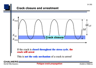
Crack closure (R)
Elber, in 1970, discovered that crack closure exists in cyclic
loading, even for loads that are greater than zero
This crack closure will decrease the fatigue crack growth rate
by reducing the effective stress intensity range
The stress intensity rate
∆K K K
K K
≡ −
= [ ]
max min
min min
max ,0
Crack closure att K=Kop gives
∆K K K
eff op
≡ −
max
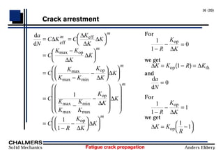
Paris law using effective stress intensity rate
d
d eff
a
N C Km
= ∆
Empirical relation
K R K
R R R R
op =
= + + − ≤ ≤
ϕ
ϕ
( )
( ) . . .
max
0 25 0 5 0 25 1 1
2](https://image.slidesharecdn.com/fatiguecrackpropagation-230509032008-469cb469/85/Fatigue-crack-propagation-pdf-13-320.jpg)