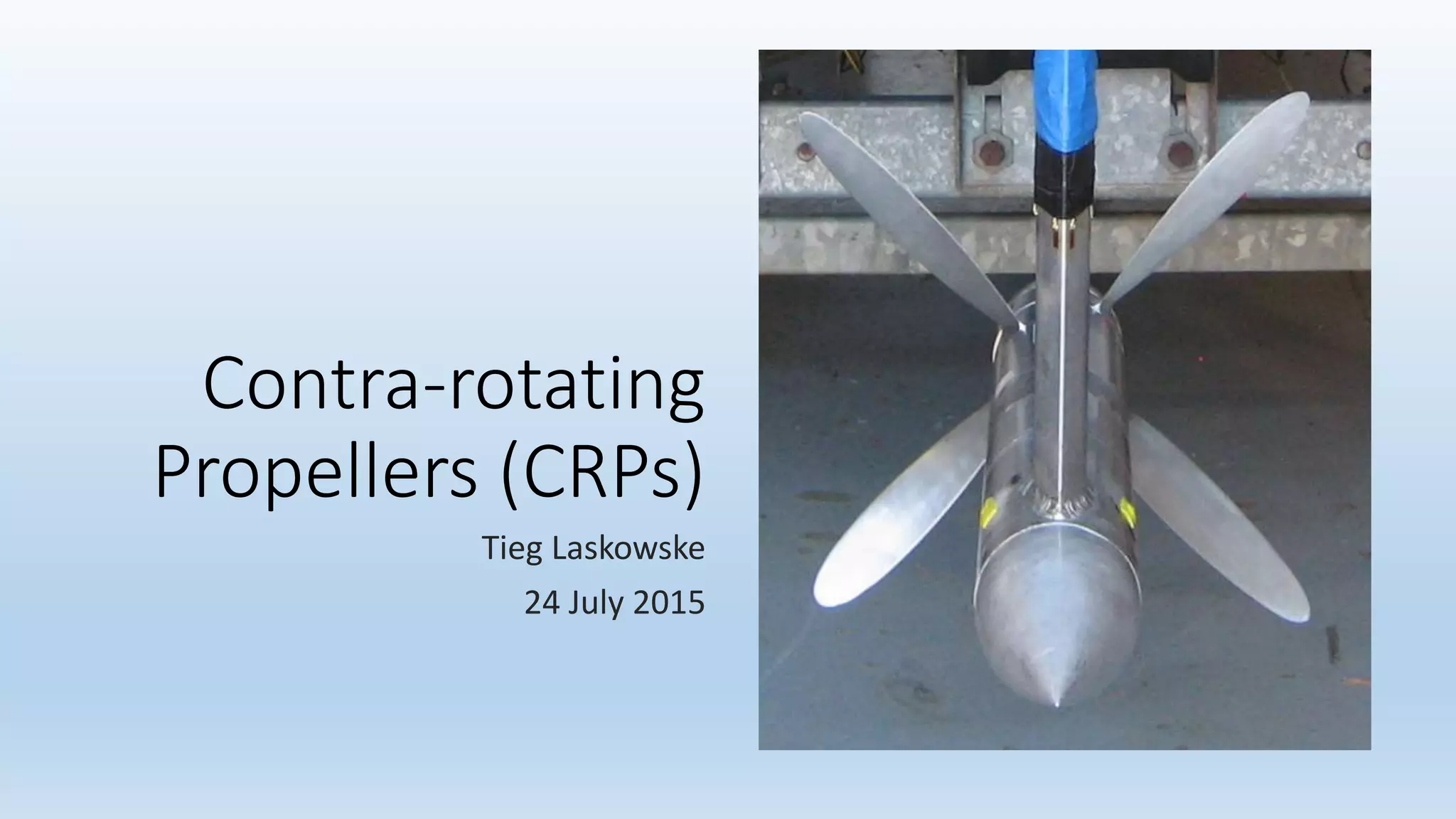
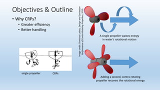
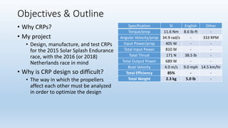
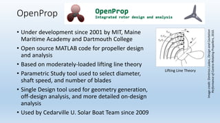
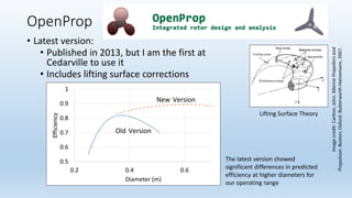
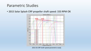
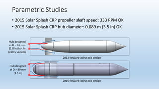
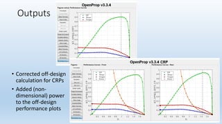
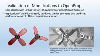
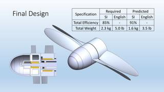
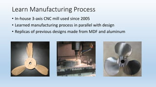
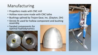
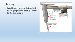
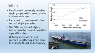
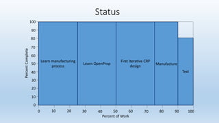
2. Objectives & Outline
A single propeller wastes energy
in water’s rotational motion
Adding a second, contra-rotating
propeller recovers the rotational energy
• Why CRPs?
• Greater efficiency
• Better handling
CRPssingle propeller
Imagecredit:DimitriosLaskos,DesignandCavitation
PerformanceofContra-RotatingPropellers,2010.
3. Objectives & Outline
Specification SI English Other
Torque/prop 11.6 Nm 8.6 lb-ft -
Angular Velocity/prop 34.9 rad/s - 333 RPM
Input Power/prop 405 W - -
Total Input Power 810 W - -
Total Thrust 171 N 38.5 lb -
Total Output Power 689 W - -
Boat Velocity 4.0 m/s 9.0 mph 14.5 km/hr
Total Efficiency 85% - -
Total Weight 2.3 kg 5.0 lb -
• Why CRPs?
• My project
• Design, manufacture, and test CRPs
for the 2015 Solar Splash Endurance
race, with the 2016 (or 2018)
Netherlands race in mind
• Why is CRP design so difficult?
• The way in which the propellers
affect each other must be analyzed
in order to optimize the design
4. Objectives & Outline
• Why CRPs?
• My project
• Why is CRP design so difficult?
• Outline
• Introduction to OpenProp
• Parametric studies
• Modifications to OpenProp
• Final design
• Manufacturing
• Testing
• Status
Specification SI English Other
Torque/prop 11.6 Nm 8.6 lb-ft -
Angular Velocity/prop 34.9 rad/s - 333 RPM
Input Power/prop 405 W - -
Total Input Power 810 W - -
Total Thrust 171 N 38.5 lb -
Total Output Power 689 W - -
Boat Velocity 4.0 m/s 9.0 mph 14.5 km/hr
Total Efficiency 85% - -
Total Weight 2.3 kg 5.0 lb -
5. OpenProp
• Under development since 2001 by MIT, Maine
Maritime Academy and Dartmouth College
• Open source MATLAB code for propeller design
and analysis
• Based on moderately-loaded lifting line theory
• Parametric Study tool used to select diameter,
shaft speed, and number of blades
• Single Design tool used for geometry generation,
off-design analysis, and more detailed on-design
analysis
• Used by Cedarville U. Solar Boat Team since 2009
Lifting Line Theory
Imagecredit:DimitriosLaskos,DesignandCavitation
PerformanceofContra-RotatingPropellers,2010.
6. OpenProp
• Latest version:
• Published in 2013, but I am the first at
Cedarville to use it
• Includes lifting surface corrections
0.5
0.6
0.7
0.8
0.9
1
0.2 0.4 0.6
Efficiency
Diameter (m)
New Version
Old Version
The latest version showed
significant differences in predicted
efficiency at higher diameters for
our operating range
Lifting Surface Theory
Imagecredit:Carlton,John.MarinePropellersand
Propulsion.Boston;Oxford:Butterworth-Heinemann,2007.
7. Parametric Studies
• 2015 Solar Splash CRP propeller shaft speed: 333 RPM OK
2015 SS CRP shaft speed parametric study
600 350
8. Parametric Studies
• 2015 Solar Splash CRP propeller shaft speed: 333 RPM OK
• 2015 Solar Splash CRP hub diameter: 0.089 m (3.5 in) OK
2013 forward-facing pod design
2015 forward-facing pod design
Hub designed
at D = 46 mm
(1.8 in) but in
reality variable
Hub designed
at D = 89 mm
(3.5 in)
9. Parametric Studies
• 2015 Solar Splash CRP propeller shaft speed: 333 RPM OK
• 2015 Solar Splash CRP hub diameter: 0.089 m (3.5 in) OK
• 2016 Netherlands CRP propeller shaft speed: 1000-2000 RPM
2013 forward-facing pod design
2015 forward-facing pod design
Hub designed
at D = 46 mm
(1.8 in) but in
reality variable
Hub designed
at D = 89 mm
(3.5 in)
10. Modifications to OpenProp
• 2009 method – assumes:
1. Induced velocity due to front propeller is the same at the two
propeller planes
2. Rear propeller does not induce velocity at the front propeller plane
• Masters Thesis of Demetrios Laskos (2010) discusses two methods of
modifying OpenProp for CRP design that avoid these assumptions
• The code Laskos used is both unavailable and outdated
• My main project this year has been to modify the most recent version
of OpenProp to implement the easier of Laskos’s methods, his so-
called ‘uncoupled’ method
• I have also made some improvements to help it suit our needs better
11. Direction of rotation
Cavitation analysis
CRP separation distance
Aft propeller
specifications
Aft propeller non-
dimensional parameters
Inputs
14. Validation of Modifications to OpenProp
Image credit: Sasaki et. al., “Design system for optimum contra-
rotating propellers,” Journal of Marine Science and Technology
(1998) 3:3-21.
• Comparison with Laskos’s results showed similar circulation distribution
• Replication of an industry study produced similar geometry and predicted
performance within 10% of experimental results
15. Validation of Modifications to OpenProp
• Comparison with Laskos’s results showed similar circulation distribution
• Replication of an industry study produced similar geometry and predicted
performance within 10% of experimental results
• Primary difference between 2009 CRP method and iterative 2015 CRP
method due to differences in tangential velocity predictions in the root
region, with the 2015 method shape matching published results more closely
2009 method 2015 method Published results
ImageCredit:Kerwin,JustinE.,WilliamB.Coney,andChing-YehHsin.Optimum
CirculationDistributionsforSingleandMulti-ComponentPropulsors.InProceedings
oftheTwenty-firstAmericanTowingTankConferenceinWashington,D.C.,August5-
7,1986,bytheNavalStudiesBoardoftheU.S.NationalResearchCouncil,53-60.
EditedbyRichardF.Messalle.Washington,D.C.:NationalAcademy,1987.
17. Learn Manufacturing Process
• In-house 3-axis CNC mill used since 2005
• Learned manufacturing process in parallel with design
• Replicas of previous designs made from MDF and aluminum
18. Manufacturing
• Propellers made with CNC mill
• Hollow nose-cone made with CNC lathe
• Bushings splined by Trojon Gear, Inc. (Dayton, OH)
• Shrink-fit used for hollow component and bushing
assembly
• Sanded components for
optimal hydrodynamics
20. Testing
• Recalibrated previously installed
strain gauges with a setup similar
to the one shown
• Ran a test to compare with the
current single propeller
• The CRPs performed slightly
better than the current propeller
(~3%), a good first step
• Unfortunately, we did not
succeed in gathering strain data
to evaluate thrust and efficiency
4.5
5.0
5.5
6.0
6.5
7.0
7.5
8.0
400 600 800 1000 1200 1400
BoatSpeed(knots)
Motor Input Power (W)
CRPs
Design Power
Single prop
Aft prop 1.8 lb Front prop and nose-cone 1.7 lb
Discuss significance of my work in OpenProp for FSC 2016
- OpenProp model improved by lifting surface corrections
- Improved CRP design tool created and validated
- GUI has been tailored for our purposes
- Detailed instructions have been written for using the program
Since 2005, the Solar Boat Team has used an in-house 3-axis CNC mill to manufacture its propellers.
In order to not be surprised at the end by the difficulty of the manufacturing process, I was advised to learn it in parallel with the design.
Since the CRPs are rotating in opposite directions, their torque cannot be measured by these strain gauges but will rather be estimated from motor data