Failed to Power Up
•
1 like•82 views

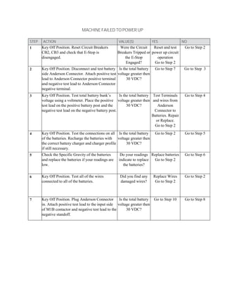
The document provides troubleshooting steps for a machine that failed to power up. It involves 29 steps to test components like batteries, wires, connectors, switches and contactors. The steps instruct the user to check for voltage at key points and replace or repair any faulty components. If the machine still does not power up after following all steps, the user is advised to contact technical support.

More Related Content
What's hot
What's hot (20)
Viewers also liked
Similar to Failed to Power Up
Similar to Failed to Power Up (20)
Failed to Power Up
- 1. MACHINE FAILED TO POWER UP STEP ACTION VALUE(S) YES NO 1 Key Off Position. Reset Circuit Breakers CB2, CB3 and check that E-Stop is disengaged. Were the Circuit Breakers Tripped or the E-Stop Engaged? Reset and test power up circuit operation Go to Step 2 Go to Step 2 2 Key Off Position. Disconnect and test battery side Anderson Connector. Attach positive test lead to Anderson Connector positive terminal and negative test lead to Anderson Connector negative terminal. Is the total battery voltage greater then 30 VDC? Go to Step 7 Go to Step 3 3 Key Off Position. Test total battery bank’s voltage using a voltmeter. Place the positive test lead on the positive battery post and the negative test lead on the negative battery post. Is the total battery voltage greater then 30 VDC? Test Terminals and wires from Anderson Connector to Batteries. Repair or Replace. Go to Step 2 Go to Step 4 4 Key Off Position. Test the connections on all of the batteries. Recharge the batteries with the correct battery charger and charger profile if still necessary. Is the total battery voltage greater then 30 VDC? Go to Step 2 Go to Step 5 5 Check the Specific Gravity of the batteries and replace the batteries if your readings are low. Do your readings indicate to replace the batteries? Replace batteries Go to Step 2 Go to Step 6 6 Key Off Position. Test all of the wires connected to all of the batteries. Did you find any damaged wires? Replace Wires Go to Step 2 Go to Step 2 7 Key Off Position. Plug Anderson Connector in. Attach positive test lead to the input side of M1B contactor and negative test lead to the negative standoff. Is the total battery voltage greater then 30 VDC? Go to Step 10 Go to Step 8
- 2. STEP ACTION VALUE(S) YES NO 8 Key Off Position. Plug Anderson Connector in. Backprobe with positive test lead to the M1 side positive Anderson Connector terminal and backprobe with negative test lead to Standoff side of the negative Anderson Connector Terminal. Is the total battery voltage greater then 30 VDC? Repair or Replace damaged wire(s) between M1 and Anderson Connector Go to Step 7 Go to Step 9 9 Key Off Position. Check all Anderson Connector terminals and connections on both sides of the Anderson Connector. Was there damage to the Anderson Connector? Repair or Replace Anderson Connector Go to Step 7 Go to Step 7 10 Key Off Position. Test Voltage to Terminal 50 (4/YEL) of the Key Switch. Place positive test lead on Terminal 50 (4/YEL) and negative test lead on negative battery terminal. Is voltage close to total battery voltage? Go to Step 15 Go to Step 11 11 Key Off Position. Test Voltage at Terminal CB3 (3/ORA). Place positive test lead on Terminal CB3 (3/ORA). Place negative test lead on negative battery terminal. Is voltage close to total battery voltage? Go to Step 13 Go to Step 12 12 Key Off Position. Test Voltage at Terminal CB3 (1/RED). Place positive test lead on Terminal CB3 (1/RED). Place negative test lead on negative battery terminal. Is voltage close to total battery voltage? Replace Circuit Breaker CB3 Go to Step 10 Check Connections, Repair or Replace Wire 1/Red Go to Step 10 13 Key Off Position. Back probe for voltage on Terminal D-2 (4/YEL). Place positive test lead on Terminal D-2 (4/YEL). Place negative test lead on negative battery terminal. Is voltage close to total battery voltage? Repair or Replace 4/YEL wire. Go to Step 10 Go to Step 14 14 Key Off Position. Back probe for voltage on Terminal D-2 (3/ORA). Place positive test lead on Terminal D-2 (3/ORA). Place negative test lead on negative battery terminal. Is voltage close to total battery voltage? Replace Diode D-2 Go to Step 10 Repair or Replace Wire 3/ORA Go to Step 10
- 3. STEP ACTION VALUE(S) YES NO 15 Key Start Position. Place positive test lead on E-Stop Switch (7/PUR) Terminal and negative test lead on negative battery terminal. (Hold key in Fully Clockwise Position) Is the voltage close to the total battery voltage? Go to Step 18 Go to Step 16 16 Key Start Position. Place positive test lead on E-Stop Switch (6/BLU) Terminal and negative test lead on negative battery terminal. (Hold key in Fully Clockwise Position) Is the voltage close to the total battery voltage? Replace E-Stop Switch Go to Step 15 Go to Step 17 17 Key Start Position. Place positive test lead on Terminal 15 (6/BLU) of the key switch and negative test lead on negative battery terminal. (Hold key in Fully Clockwise Position) Is the voltage close to the total battery voltage? Repair or Replace Wire 6/BLU Go to Step 15 Replace Key Switch Go to Step 15 18 Key Start Position. Place positive test lead on Charger Interlock (8/GRY) Terminal and negative test lead on negative battery terminal. (Hold key in Fully Clockwise Position) Is the voltage close to the total battery voltage? Go to Step 21 Go to Step 19 19 Key Start Position. Place positive test lead on Charger Interlock (7/PUR) Terminal and negative test lead on negative battery terminal. (Hold key in Fully Clockwise Position) Is the voltage close to the total battery voltage? Go to Step 20 Repair or Replace Wire 7/PUR Go to Step 18 20 Check the Charger Interlock Switch to make sure that the wire 7/PUR is plugged into the common terminal of the switch and that wire 8/GRY is plugged into the Normally Closed terminal of the switch. Is the charger interlock switch plugged in correctly? Replace Switch Go to Step 18 Plug Charger Interlock Switch in Correctly Go to Step 18 21 Key Start Position. Place positive test lead on M1A (8/GRY) Terminal and negative test lead on negative battery terminal. (Hold key in Fully Clockwise Position) Is the voltage close to the total battery voltage? Go to Step 22 Repair or Replace Wire 8/GRY Go to Step 22
- 4. STEP ACTION VALUE(S) YES NO 22 Key Start Position. Place positive test lead on M1A (8/GRY) Terminal and negative test lead M1A (13/BLK) Terminal. (Hold key in Fully Clockwise Position) Is the voltage close to the total battery voltage? Replace M1 Contactor Go to Step 23 Repair or Replace Negative Wire 13/BLK Go to Step 23 23 Key Start Position. Observe if M1 contactor is energized. Place positive test lead on M1B contactor output and negative test lead on negative battery terminal. (Hold key in Fully Clockwise Position) Is the voltage close to the total battery voltage? Go to Step 24 Replace M1 Contactor Go to Step 24 24 Key Start Position. Place positive test lead on Terminal 30 (5/GRN) and negative test lead on negative battery terminal. (Hold key in Fully Clockwise Position) Is the voltage close to the total battery voltage? Go to Step 29. Go to Step 25. 25 Key Start Position. Place positive test lead on Terminal CB2 (10/Tan) and negative test lead on negative battery terminal. (Hold key in Fully Clockwise Position) Is the voltage close to the total battery voltage? Go to Step 27. Go to Step 26. 26 Key Start Position. Place positive test lead on Terminal CB2 (2/BRN) and negative test lead on negative battery terminal. (Hold key in Fully Clockwise Position) Is the voltage close to the total battery voltage? Replace Circuit Breaker CB-2. Go to Step 24. Repair or Replace Wire 2/BRN Go to Step 24. 27 Key Start Position. Place positive test lead on Terminal D-1 (5/GRN) and negative test lead on negative battery terminal. (Hold key in Fully Clockwise Position) Is the voltage close to the total battery voltage? Repair or Replace Wire 5/GRN Go to Step 24 Go to Step 28 28 Key Start Position. Place positive test lead on Terminal D-1 (10/TAN) and negative test lead on negative battery terminal. (Hold key in Fully Clockwise Position) Is the voltage close to the total battery voltage? Replace Diode D-1 Go to Step 24 Repair or Replace Wire 10/TAN Go to Step 24
- 5. STEP ACTION VALUE(S) YES NO 29 Key Start Position listen for click of Contactor M1. Let key go to Key Run(On) Position. Does Machine Power up correctly? Run a Self test to determine if any other systems have faults. Finish up and close out. Contact Tech Support who will assist you with difficult problems. VDC = Volts Direct Current After Replacing a Component, Fixing a Wire, or repairing a problem. Check for Machine Power Up. Key Start Position = Holding key in fully clockwise position like starting a car. Key Run(On) Position = Vehicle is running and key has been let go of. 30 VDC is a bottom reference voltage for a T12 being able to function. If a new part does not function after installing it, take the new part out and test it. Ladder diagrams show electrical components in their electrical sequence of operation not in their physical locations. As a general rule ladder diagrams are read from left to right and top to bottom. M1 Contactor = The Entire Solenoid (The Coil and the Contacts) Contacts with the same letter or number as the coil are controlled by that coil. (Example M1A = The Coil and M1B = The Contacts) Dashed lines between components mean that they are mechanically connected. (Example Terminal 50 (4/YEL) ------- Terminal 15 (6/BLU) and Terminal 30 (5/GRN) ------- Terminal 15 (6/BLU) )