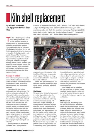
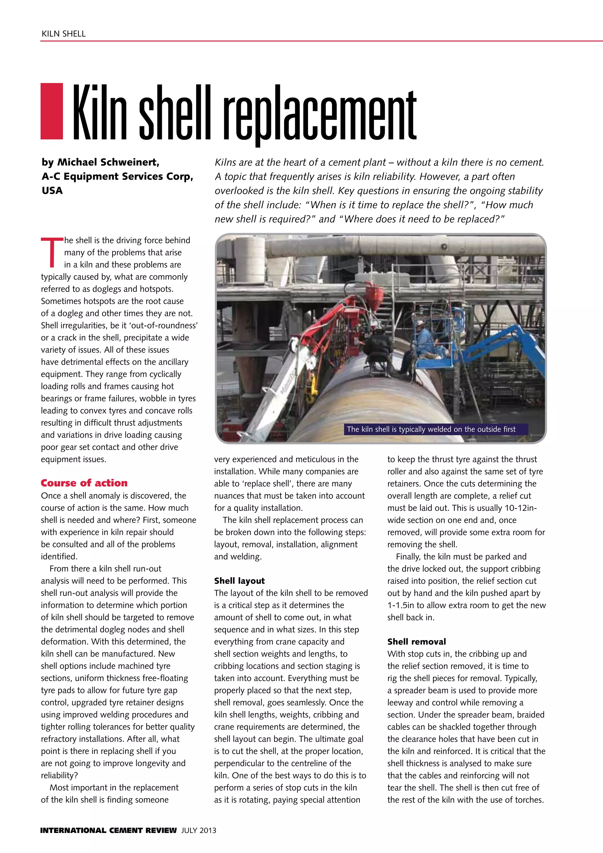
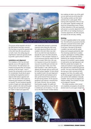
INTERNATIONAL CEMENT REVIEW JULY 2013
T
he shell is the driving force behind
many of the problems that arise
in a kiln and these problems are
typically caused by, what are commonly
referred to as doglegs and hotspots.
Sometimes hotspots are the root cause
of a dogleg and other times they are not.
Shell irregularities, be it ‘out-of-roundness’
or a crack in the shell, precipitate a wide
variety of issues. All of these issues
have detrimental effects on the ancillary
equipment. They range from cyclically
loading rolls and frames causing hot
bearings or frame failures, wobble in tyres
leading to convex tyres and concave rolls
resulting in difficult thrust adjustments
and variations in drive loading causing
poor gear set contact and other drive
equipment issues.
Course of action
Once a shell anomaly is discovered, the
course of action is the same. How much
shell is needed and where? First, someone
with experience in kiln repair should
be consulted and all of the problems
identified.
From there a kiln shell run-out
analysis will need to be performed. This
shell run-out analysis will provide the
information to determine which portion
of kiln shell should be targeted to remove
the detrimental dogleg nodes and shell
deformation. With this determined, the
kiln shell can be manufactured. New
shell options include machined tyre
sections, uniform thickness free-floating
tyre pads to allow for future tyre gap
control, upgraded tyre retainer designs
using improved welding procedures and
tighter rolling tolerances for better quality
refractory installations. After all, what
point is there in replacing shell if you
are not going to improve longevity and
reliability?
Most important in the replacement
of the kiln shell is finding someone
very experienced and meticulous in the
installation. While many companies are
able to ‘replace shell’, there are many
nuances that must be taken into account
for a quality installation.
The kiln shell replacement process can
be broken down into the following steps:
layout, removal, installation, alignment
and welding.
Shell layout
The layout of the kiln shell to be removed
is a critical step as it determines the
amount of shell to come out, in what
sequence and in what sizes. In this step
everything from crane capacity and
shell section weights and lengths, to
cribbing locations and section staging is
taken into account. Everything must be
properly placed so that the next step,
shell removal, goes seamlessly. Once the
kiln shell lengths, weights, cribbing and
crane requirements are determined, the
shell layout can begin. The ultimate goal
is to cut the shell, at the proper location,
perpendicular to the centreline of the
kiln. One of the best ways to do this is to
perform a series of stop cuts in the kiln
as it is rotating, paying special attention
to keep the thrust tyre against the thrust
roller and also against the same set of tyre
retainers. Once the cuts determining the
overall length are complete, a relief cut
must be laid out. This is usually 10-12in-
wide section on one end and, once
removed, will provide some extra room for
removing the shell.
Finally, the kiln must be parked and
the drive locked out, the support cribbing
raised into position, the relief section cut
out by hand and the kiln pushed apart by
1-1.5in to allow extra room to get the new
shell back in.
Shell removal
With stop cuts in, the cribbing up and
the relief section removed, it is time to
rig the shell pieces for removal. Typically,
a spreader beam is used to provide more
leeway and control while removing a
section. Under the spreader beam, braided
cables can be shackled together through
the clearance holes that have been cut in
the kiln and reinforced. It is critical that the
shell thickness is analysed to make sure
that the cables and reinforcing will not
tear the shell. The shell is then cut free of
the rest of the kiln with the use of torches.
IKilnshellreplacementby Michael Schweinert,
A-C Equipment Services Corp,
USA
Kilns are at the heart of a cement plant – without a kiln there is no cement.
A topic that frequently arises is kiln reliability. However, a part often
overlooked is the kiln shell. Key questions in ensuring the ongoing stability
of the shell include: “When is it time to replace the shell?”, “How much
new shell is required?” and “Where does it need to be replaced?”
kiln SHELL
The kiln shell is typically welded on the outside first
JULY 2013 INTERNATIONAL CEMENT REVIEW
This process will be repeated until all of
the shell sections have been removed.
The final step is to grind the exposed ends
of the shell. Since the new joints were
cut with a torch, the cutting slag and
imperfections need to be ground smooth
to provide a good surface to weld to.
Installation and alignment
The installation of the new kiln shell
typically occurs in the opposite order
of the removal. The shell sections are
hoisted ensuring that they are hanging
perfectly on the kiln slope – once in
location this will provide an even joint to
fit. Consideration should also be given
to installing the longitudinal seams in
adjacent shell sections opposite each
other. The kiln shell is held in place by
temporary joint hardware and cribbing
as required. The joint hardware typically
consists of angles and radial adjustment
blocks, welded to the shell and threaded
through rods and nuts that fit through
the angles to adjust and support the
shell. Radial shell mismatch is extremely
important when fitting the shell using
the radial adjustment blocks that were
installed in the shell. When new shell
fits to new shell, the inside diameter is
typically the same, thus there should be
less than a 1/16in mismatch. However, it
is not uncommon that the inside of the old
shell is corroded. When this is the case,
it is important to ensure the mismatch is
very even around the joint and does not
vary by more than 1/16in, even if the
total mismatch is 1/8in. With the joints
aligned, the through rods are used to pull
the shell sections together. Tie bars should
be installed to lock in the joint alignment
attained with the joint hardware and to
take up the torsional forces exerted on
the joint during rotation. At this point all
equipment and material is removed from
the inside of the kiln. Run-out stands,
fixed location roughly 12in uphill and
downhill of each joint are set up. The kiln
is rotated and a set of stations, 1-12, laid
out on the shell. At each of these stations
two readings are taken, one at the uphill
run-out stand and one at the downhill.
The resulting numbers are then taken
and laid out on a polar graph. When
looking at the magnitude of the run-out
on a polar graph, opposite readings will
show any corresponding moves. Several
of these indications in the same quadrant
will warrant a corrective adjustment of the
joint. With run-out readings showing no
corrective adjustment, the shell and joints
are ready for the next step, welding.
Welding
The shell is typically welded on the outside
first. The shell joints are ground so that the
mill scale is removed several inches uphill
and downhill of the actual joints bevel.
A root pass in the base of the bevels
is welded in by hand with the welder
taking care to properly preheat the shell.
The remaining outside bevel is welded
using the submerged arc welding (SAW)
process. SAW is the preferred welding
method for the majority of the bevel
because of its consistent, superior quality
of weld and its very high deposition rate.
With the outside bevel complete, the
inside joint hardware is back-gouged off,
the spots that were welded being ground
smooth. The nose of the bevel along with
the seal pass is then removed via back-
gouging. From there, the welders weld
up the back-gouged inside portion of the
joint and the shell installation is basically
complete. Tyres can then be aligned and
retainers welded. Once finished, the gear
can be aligned if required.
This simple procedure, when carried
out completely and properly, will yield the
desired result of a once again straight kiln.
_______________________________I
kiln SHELL
The kiln shell replacement process can be broken down into the
following steps: layout, removal, installation, alignment and welding
The kiln is ready to receive a new shell section
After the kiln is parked and the drive locked out, the support
cribbbing is raised into position and the relief section is cut by hand

Kiln shell

  • 1.
    INTERNATIONAL CEMENT REVIEWJULY 2013 T he shell is the driving force behind many of the problems that arise in a kiln and these problems are typically caused by, what are commonly referred to as doglegs and hotspots. Sometimes hotspots are the root cause of a dogleg and other times they are not. Shell irregularities, be it ‘out-of-roundness’ or a crack in the shell, precipitate a wide variety of issues. All of these issues have detrimental effects on the ancillary equipment. They range from cyclically loading rolls and frames causing hot bearings or frame failures, wobble in tyres leading to convex tyres and concave rolls resulting in difficult thrust adjustments and variations in drive loading causing poor gear set contact and other drive equipment issues. Course of action Once a shell anomaly is discovered, the course of action is the same. How much shell is needed and where? First, someone with experience in kiln repair should be consulted and all of the problems identified. From there a kiln shell run-out analysis will need to be performed. This shell run-out analysis will provide the information to determine which portion of kiln shell should be targeted to remove the detrimental dogleg nodes and shell deformation. With this determined, the kiln shell can be manufactured. New shell options include machined tyre sections, uniform thickness free-floating tyre pads to allow for future tyre gap control, upgraded tyre retainer designs using improved welding procedures and tighter rolling tolerances for better quality refractory installations. After all, what point is there in replacing shell if you are not going to improve longevity and reliability? Most important in the replacement of the kiln shell is finding someone very experienced and meticulous in the installation. While many companies are able to ‘replace shell’, there are many nuances that must be taken into account for a quality installation. The kiln shell replacement process can be broken down into the following steps: layout, removal, installation, alignment and welding. Shell layout The layout of the kiln shell to be removed is a critical step as it determines the amount of shell to come out, in what sequence and in what sizes. In this step everything from crane capacity and shell section weights and lengths, to cribbing locations and section staging is taken into account. Everything must be properly placed so that the next step, shell removal, goes seamlessly. Once the kiln shell lengths, weights, cribbing and crane requirements are determined, the shell layout can begin. The ultimate goal is to cut the shell, at the proper location, perpendicular to the centreline of the kiln. One of the best ways to do this is to perform a series of stop cuts in the kiln as it is rotating, paying special attention to keep the thrust tyre against the thrust roller and also against the same set of tyre retainers. Once the cuts determining the overall length are complete, a relief cut must be laid out. This is usually 10-12in- wide section on one end and, once removed, will provide some extra room for removing the shell. Finally, the kiln must be parked and the drive locked out, the support cribbing raised into position, the relief section cut out by hand and the kiln pushed apart by 1-1.5in to allow extra room to get the new shell back in. Shell removal With stop cuts in, the cribbing up and the relief section removed, it is time to rig the shell pieces for removal. Typically, a spreader beam is used to provide more leeway and control while removing a section. Under the spreader beam, braided cables can be shackled together through the clearance holes that have been cut in the kiln and reinforced. It is critical that the shell thickness is analysed to make sure that the cables and reinforcing will not tear the shell. The shell is then cut free of the rest of the kiln with the use of torches. IKilnshellreplacementby Michael Schweinert, A-C Equipment Services Corp, USA Kilns are at the heart of a cement plant – without a kiln there is no cement. A topic that frequently arises is kiln reliability. However, a part often overlooked is the kiln shell. Key questions in ensuring the ongoing stability of the shell include: “When is it time to replace the shell?”, “How much new shell is required?” and “Where does it need to be replaced?” kiln SHELL The kiln shell is typically welded on the outside first
  • 2.
    JULY 2013 INTERNATIONALCEMENT REVIEW This process will be repeated until all of the shell sections have been removed. The final step is to grind the exposed ends of the shell. Since the new joints were cut with a torch, the cutting slag and imperfections need to be ground smooth to provide a good surface to weld to. Installation and alignment The installation of the new kiln shell typically occurs in the opposite order of the removal. The shell sections are hoisted ensuring that they are hanging perfectly on the kiln slope – once in location this will provide an even joint to fit. Consideration should also be given to installing the longitudinal seams in adjacent shell sections opposite each other. The kiln shell is held in place by temporary joint hardware and cribbing as required. The joint hardware typically consists of angles and radial adjustment blocks, welded to the shell and threaded through rods and nuts that fit through the angles to adjust and support the shell. Radial shell mismatch is extremely important when fitting the shell using the radial adjustment blocks that were installed in the shell. When new shell fits to new shell, the inside diameter is typically the same, thus there should be less than a 1/16in mismatch. However, it is not uncommon that the inside of the old shell is corroded. When this is the case, it is important to ensure the mismatch is very even around the joint and does not vary by more than 1/16in, even if the total mismatch is 1/8in. With the joints aligned, the through rods are used to pull the shell sections together. Tie bars should be installed to lock in the joint alignment attained with the joint hardware and to take up the torsional forces exerted on the joint during rotation. At this point all equipment and material is removed from the inside of the kiln. Run-out stands, fixed location roughly 12in uphill and downhill of each joint are set up. The kiln is rotated and a set of stations, 1-12, laid out on the shell. At each of these stations two readings are taken, one at the uphill run-out stand and one at the downhill. The resulting numbers are then taken and laid out on a polar graph. When looking at the magnitude of the run-out on a polar graph, opposite readings will show any corresponding moves. Several of these indications in the same quadrant will warrant a corrective adjustment of the joint. With run-out readings showing no corrective adjustment, the shell and joints are ready for the next step, welding. Welding The shell is typically welded on the outside first. The shell joints are ground so that the mill scale is removed several inches uphill and downhill of the actual joints bevel. A root pass in the base of the bevels is welded in by hand with the welder taking care to properly preheat the shell. The remaining outside bevel is welded using the submerged arc welding (SAW) process. SAW is the preferred welding method for the majority of the bevel because of its consistent, superior quality of weld and its very high deposition rate. With the outside bevel complete, the inside joint hardware is back-gouged off, the spots that were welded being ground smooth. The nose of the bevel along with the seal pass is then removed via back- gouging. From there, the welders weld up the back-gouged inside portion of the joint and the shell installation is basically complete. Tyres can then be aligned and retainers welded. Once finished, the gear can be aligned if required. This simple procedure, when carried out completely and properly, will yield the desired result of a once again straight kiln. _______________________________I kiln SHELL The kiln shell replacement process can be broken down into the following steps: layout, removal, installation, alignment and welding The kiln is ready to receive a new shell section After the kiln is parked and the drive locked out, the support cribbbing is raised into position and the relief section is cut by hand