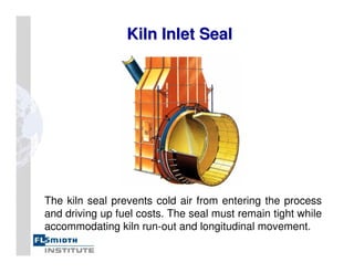
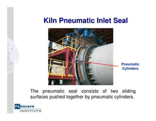
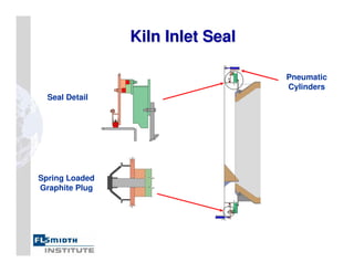
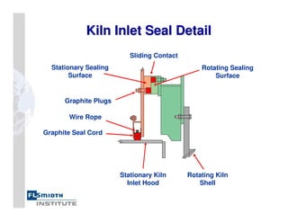
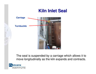
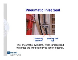
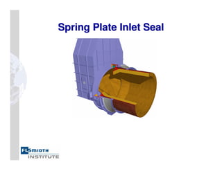
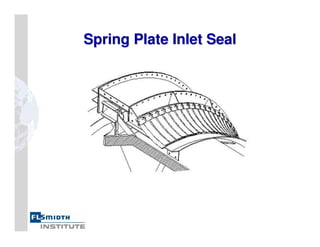
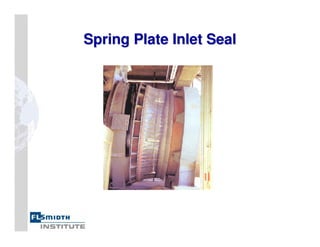
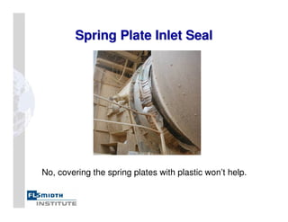
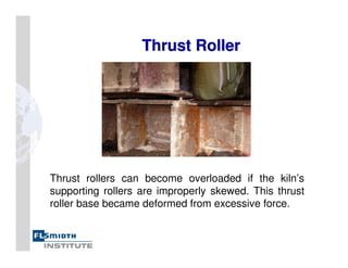
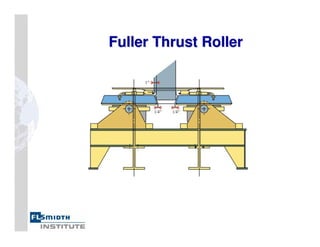
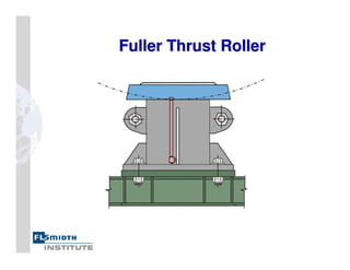
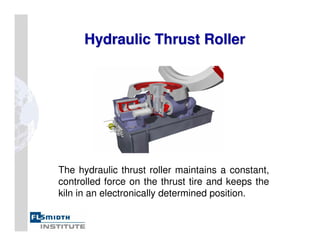
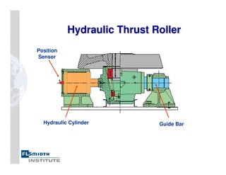
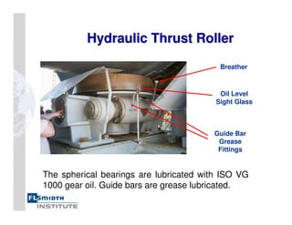
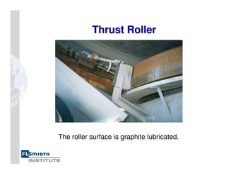
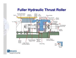
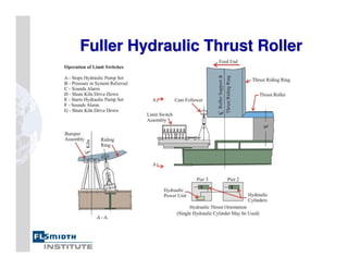
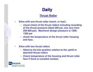
Rotary Kiln Maintenance
Seminar
Seminar
Kiln Miscellaneous
Kiln Inlet Seal
Kiln Outlet Seal
Thrust Roller
Hydraulic Thrust Roller
Kiln Maintenance Checklist
The Good Old Days
Kiln Miscellaneous
Kiln Miscellaneous
Kiln Inlet Seal
Kiln Inlet Seal
Kiln Inlet Seal
Kiln Inlet Seal
The kiln seal prevents cold air from entering the process
and driving up fuel costs. The seal must remain tight while
accommodating kiln run-out and longitudinal movement.
Kiln Pneumatic Inlet Seal
The pneumatic seal consists of two sliding
surfaces pushed together by pneumatic cylinders.
Pneumatic
Cylinders
Kiln Inlet Seal
Kiln Inlet Seal
Spring Loaded
Graphite Plug
Seal Detail
Pneumatic
Cylinders
Kiln Inlet Seal Detail
Graphite Seal Cord
Wire Rope
Graphite Plugs
Rotating Kiln
Shell
Rotating Sealing
Surface
Stationary Sealing
Surface
Sliding Contact
Stationary Kiln
Inlet Hood
Kiln Inlet Seal
Kiln Inlet Seal
The seal is suspended by a carriage which allows it to
move longitudinally as the kiln expands and contracts.
Carriage
Turnbuckle
Pneumatic Inlet Seal
The pneumatic cylinders, when pressurized,
will press the two seal halves tightly together.
Stationary
Seal Half
Rotating Seal
Half
Filter, Regulator, Lubricator
Cylinder force is controlled by adjusting the air pressure.
A lubricator prevents cylinder corrosion and seize-up.
The filter keeps condensation and dirt out of the cylinder.
Filter, Regulator, Lubricator
Kiln Inlet Seal
Kiln Inlet Seal
The seal’s sliding surfaces are graphite lubricated.
Spring Loaded
Graphite Plug
Graphite Plugs in
Seal Plate
Kiln Inlet Castings
Kiln Inlet Castings
Castings on the inlet hood and kiln inlet
cone keep the castable refractory in
place. Inspect them at annual shutdown.
Spring Plate Inlet Seal
No, covering the spring plates with plastic won’t help.
Spring Plate Inlet Seal
Outlet Seal
Outlet Seal
Kiln Outlet Seal
Kiln Outlet Seal
The spring plate outlet seal has become the
outlet seal of choice. The seal can withstand
the harsh conditions at the kiln hood.
Kiln Outlet Seal
Kiln Outlet Seal
Spring Plate Wire
Rope
Kiln Outlet Seal
Kiln Outlet Seal
Counterweight
Spring plates are wrapped with a counterweighted wire
rope arrangement to keep them tight against the cowl.
Forced
Air
Cooling
Kiln Outlet Seal
Kiln Outlet Seal
A stainless steel cowl at the kiln outlet provides an
air channel for cooling of the kiln discharge castings
and the spring plate contact surface.
Kiln Outlet Seal
Kiln Outlet Seal
Spring plates are bolted on and are easily replaced.
Kiln Outlet
Kiln Outlet Seal
Seal
Dust from kiln hood puffing falls down the chutes to
the drag chain conveyor or into the clinker cooler.
The Old Way The Better Way
Kiln Outlet Sector
Kiln Outlet Sector
The kiln nose rings sees severe service and must be
regularly inspected for refractory and casting failure.
Kiln Outlet Seal
Kiln Outlet Seal
This alternate spring plates design features
outwardly protruding spring plates.
Kiln Outlet Seal
Kiln Outlet Seal
Outwardly protruding spring plate design.
The Most Expensive Seal
A bad seal allows cold air into the kiln. The cost
of extra fuel to heat this cold air can amount to
tens of thousands of dollars per year.
Thrust Roller
Thrust Roller
Thrust Roller Assembly
Oil
Seal
Oil Level
Pipe
Spherical
Bearings
Tie
Rod
Tire
Shims
Clearance
Keep the clearance to a minimum (6mm),
and adjust the shims to keep the kiln gear
in proper longitudinal alignment.
Thrust Roller Assembly
Set
Screws
The kiln position can be controlled by
adjusting set screws on this thrust roller base.
Thrust Roller Position
Stop Ring
Thrust
Tire
The thrust roller is positioned to maintain proper hot
running alignment between kiln gear and pinion.
Repositioning may be necessary as stop rings wear.
Thrust Roller Misalignment
A misaligned thrust roller will result in vertical forces
on the roller as shown above.
Roller Tilted to Left Roller Tilted to Right
Roller Offset to Left Roller Offset to Right
Thrust Roller Misalignment
An improperly aligned thrust roller can ride out of
its socket, causing damage to tire stop blocks.
Thrust Roller
Thrust Roller
Thrust rollers can become overloaded if the kiln’s
supporting rollers are improperly skewed. This thrust
roller base became deformed from excessive force.
Fuller Thrust Roller
Hydraulic Thrust Roller
The hydraulic thrust roller maintains a constant,
controlled force on the thrust tire and keeps the
kiln in an electronically determined position.
Hydraulic Thrust Roller
Guide Bar
Hydraulic Cylinder
Position
Sensor
Hydraulic Thrust Roller
Breather
Oil Level
Sight Glass
Guide Bar
Grease
Fittings
The spherical bearings are lubricated with ISO VG
1000 gear oil. Guide bars are grease lubricated.
Thrust Roller
Thrust Roller
The roller surface is graphite lubricated.
Hydraulic Thrust Roller
Hydraulic Cabinet
Hydraulic Cabinet
The hydraulic power unit is normally
placed beneath the kiln’s thrust pier.
Hydraulic Cabinet
Hydraulic Cabinet
Accumulator
Pump
Directional
Valve
Relief
Valve
Tank
Hydraulic Pump
Hydraulic Pump
The axial piston pump has manual
adjustments for pressure and flow rate.
Directional Valve
Directional Valve
A directional valve directs fluid to the thrust
cylinder, or allows the cylinder to bleed down.
Hydro
Hydro-
-pneumatic Accumulator
pneumatic Accumulator
An accumulator stores hydraulic energy. It is used to
maintain a steady force on the thrust tire even
though the tire wobbles slightly as the kiln turns.
Gas Valve
Bladder
Shell
Port
Anti-Extrusion
Valve
Nitrogen Gas
Hydro
Hydro-
-pneumatic Accumulator
pneumatic Accumulator
The accumulator contains a rubber bladder
which is charged with nitrogen gas.
psig
0
500
1000
1500
2000
psig
0
500
1000
1500
2000
psig
0
500
1000
1500
2000
System Pressure
Less Than pprecharge
System Pressure
at pmax
System Pressure
at pmin
Hydro
Hydro-
-pneumatic Accumulator
pneumatic Accumulator
When hydraulic pressure increases and decreases
the gas is compressed and expanded.
Hydro
Hydro-
-pneumatic Accumulator
pneumatic Accumulator
The accumulator is pre-charged with nitrogen
to approximately half of the expected average
operating hydraulic pressure.
Danger!
Do not charge with
air or oxygen!
Pressure Relief Valve
A pressure relief valve limits hydraulic pressure in
the system. This prevents excessive downhill kiln
force from damaging the thrust roller.
Hydraulic Filter
Hydraulic Filter
An in-tank filter with a 10 micron element
keeps hydraulic fluid clean. The protruding red
button indicates the element needs changing.
Thrust Cylinder LVDT
An LVDT (linear variable differential transformer)
mounted in the hydraulic cylinder measures the
distance that the cylinder rod is extended.
Thrust System LVDT Cabinet
The LVDT signal goes to a cabinet where the kiln’s hot
running axial position is set and where alarms are
programmed for excessive uphill and downhill kiln position.
Fuller Hydraulic Thrust Roller
Preventive Maintenance Checklist
Daily
Daily
Thrust Roller
• Kilns with one thrust roller (mech. or hyd.)
– visual check of the thrust rollers including recording
of the thrust pressure (ideal 500 psi, can vary from
200-800 psi). Maximum design pressure is 1200-
1300 psi
– check the temperature of the thrust roller housing
and face.
• Kilns with two thrust rollers
– Observe the kiln position relative to the uphill or
downhill thrust rollers
– Check temperature of the housing and thrust roller
face if there is constant contact.
Seals
• Visually check feed and discharge seals
Gear
• Visually check the gear and pinion
Rollers and Live Rings
• Visually check all roller and tire surfaces
• Lubricate contact faces between tires and shell
mounted tire pads and stop blocks using a mixture of
graphite powder and water.
Daily
Daily
Temperatures
• Record kiln shell temperatures and
include a night visual inspection for “hot
spots”
Daily
Daily
Weekly
Weekly
• Check and record direction of thrust on all
rollers.
• Check lubrication on all support rollers.
• Check oil levels in support roller bearings
and thrust roller bearings.
• Check and record the tire creep and
clearance.
• Record related shell and tire temperatures.
• Check condition of tire stop blocks and
wear rings.
• Check general condition of kiln
shell.
• Check contact patterns between
gear and pinion by observing the
oil smear on the contact face for at
least one full kiln rotation.
Weekly
Weekly
Annually
Annually
• Perform complete check of kiln alignment
utilizing the laser or mechanical alignment
method. Kiln alignments should be completed
after major repairs have been made to the kiln.
• With this information recorded and compared,
a problem should be caught before a real
dilemma occurs (i.e. an unplanned shutdown).
• Prior to planned kiln shutdowns, an extensive
mechanical inspection should be completed to
determine repairs required.
The Good Old Days
The Good Old Days
The Good Old Days
The Good Old Days
The Good Old Days
The Good Old Days
Rivets
Rivets
Don’t Be Mean to Your Kiln

304372312-Kiln-Miscellaneous.pdf