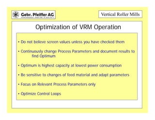
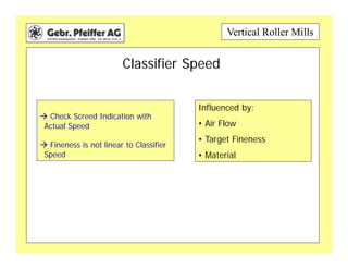
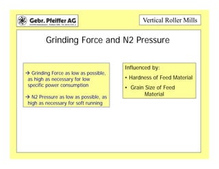
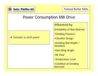
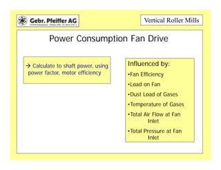
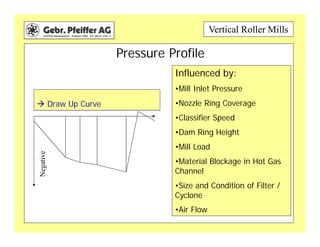
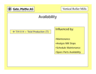
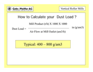
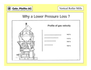
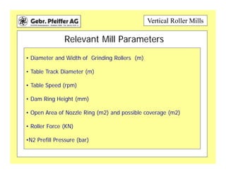
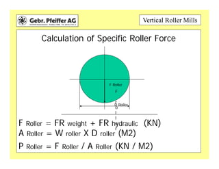
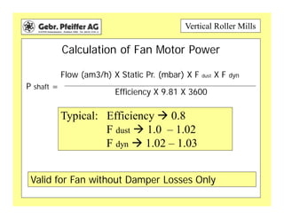
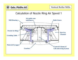
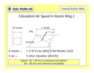
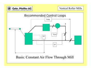
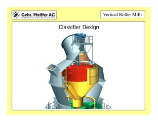
Vertical Roller Mills
• Do not believe screen values unless you have checked them
• Continuously change Process Parameters and document results to
find Optimum
• Optimum is highest capacity at lowest power consumption
• Be sensitive to changes of feed material and adapt parameters
• Focus on Relevant Process Parameters only
• Optimize Control Loops
Optimization of VRM Operation
Vertical Roller Mills
• Product Rate and Product Fineness (T/H)
• Classifier Speed (rpm)
• Grinding Force and N2 Pressure
• Power Consumption Main and Fan Drive (KW)
• Air Flow Profile (am3/h) and Pressure Profile (mbar)
• Availability (% relative to kiln)
• Grinding Bed Height (mm) and Variations (mm)
Relevant Process Parameters
Vertical Roller Mills
Product Rate and Product Fineness
 Correct Feed Rate to measured
moisture
Check fineness on 90 and 212
micron
Comments:
•Do not over grind
•Check burnability and 212
micron sieve
Vertical Roller Mills
Classifier Speed
 Check Screed Indication with
Actual Speed
 Fineness is not linear to Classifier
Speed
Influenced by:
• Air Flow
• Target Fineness
• Material
Vertical Roller Mills
Grinding Force and N2 Pressure
 Grinding Force as low as possible,
as high as necessary for low
specific power consumption
 N2 Pressure as low as possible, as
high as necessary for soft running
Influenced by:
• Hardness of Feed Material
• Grain Size of Feed
Material
Vertical Roller Mills
What is the Optimum N2 Pressure ?
N2 Pressure bed too low, ->
Rough Running
N2 Pressure, OK, ->controlled
roller movement, Efficient
Grinding
N2 Pressure too high, -
>Excessive Roller Movement,
Inefficient Grinding, Rough
Running
Vertical Roller Mills
 Calculate to shaft power
Influenced by:
Grindability of Raw Material
•Grinding Fineness
•Classifier Design
•Grinding Bed Height /
Variations
•Dam Ring Height
•Air Flow
•Temperature Level
•Condition of Grinding
Elements
Power Consumption Mill Drive
Vertical Roller Mills
Power Consumption Fan Drive
 Calculate to shaft power, using
power factor, motor efficiency
Influenced by:
•Fan Efficiency
•Load on Fan
•Dust Load of Gases
•Temperature of Gases
•Total Air Flow at Fan
Inlet
•Total Pressure at Fan
Inlet
Vertical Roller Mills
Air Flow Profile
 Check for False Air Leakage
because:
•False air after nozzle ring
reduces grinding capacity
• Any false air reduces drying
capacity
Influenced by:
Expansion Joints
•Flanges
•Pull Rod Seals
•Negative Pressure
•Feeding Device to Mill
•Air Locks after Filter /
Cyclones
Vertical Roller Mills
Pressure Profile
 Draw Up Curve
Influenced by:
•Mill Inlet Pressure
•Nozzle Ring Coverage
•Classifier Speed
•Dam Ring Height
•Mill Load
•Material Blockage in Hot Gas
Channel
•Size and Condition of Filter /
Cyclone
•Air Flow
Negative
Vertical Roller Mills
Availability
 T/H X H = Total Production (T)
Influenced by:
•Maintenance
•Analyze Mill Stops
•Schedule Maintenance
•Spare Parts Availability
Vertical Roller Mills
Basic Questions
For Operation of VRM s
Vertical Roller Mills
What is a Grinding Bed ?
Grinding bed is the material layer
between the roller and the table
It transmits the entire roller force
and mill power
It is the key issue to successful
operating of a VRM !!!
Determined by:
•Feed Material size
•Feed Material Moisture
•Dam Ring Height
•Grinding Fineness
•Air Speed in nozzle ring
Vertical Roller Mills
Redesigned – Table Segments
•More Flat
Grinding Bed
•Less Weight to be
Handled
•Longer Lifetime
of Table Segments
Vertical Roller Mills
What is the Optimum Grinding Bed Height ?
Grinding bed too
low, -> Vibration
Grinding bed, OK, ->little Vibration, Efficient
Grinding
Grinding bed too high, ->Vibration Inefficient
Grinding
X
Vertical Roller Mills
How to Calculate your Dust Load ?
Dust Load =
Mill Product (t/h) X 1000 X 1000
Air Flow at Mill Outlet (am3/h)
in (g/am3)
Typical Numbers = 400 – 800 g/am3
Typical: 400 – 800 g/am3
Vertical Roller Mills
What determines your Dust Load ?
Vertical Roller Mills
Why a Lower Pressure Loss ?
Vertical Roller Mills
• Diameter and Width of Grinding Rollers (m)
• Table Track Diameter (m)
• Table Speed (rpm)
• Dam Ring Height (mm)
• Open Area of Nozzle Ring (m2) and possible coverage (m2)
• Roller Force (KN)
•N2 Prefill Pressure (bar)
Relevant Mill Parameters
Vertical Roller Mills
Basic Calculations
For Operation of VRM s
Vertical Roller Mills
Calculation of Specific Roller Force
F Roller = FR weight + FR hydraulic (KN)
A Roller = W roller X D roller (M2)
P Roller = F Roller / A Roller (KN / M2)
F
r
o
l
l
e
r
F Roller
D Roller
Vertical Roller Mills
Calculation of Fan Motor Power
P shaft =
Valid for Fan without Damper Losses Only
Flow (am3/h) X Static Pr. (mbar) X F dust X F dyn
Efficiency X 9.81 X 3600
Typical: Efficiency  0.8
F dust  1.0 – 1.02
F dyn  1.02 – 1.03
Vertical Roller Mills
Calculation of Nozzle Ring Air Speed 1
Ported Air Ring
Air guide cone
with liners
Mill Housing Table Liners
Hot Gas
Channel
Material Scrapper
Gearbox
Central Column of
Lift-and-swing System
Grinding Table
Vertical Roller Mills
Calculation Air Speed in Nozzle Ring 2
F
r
o
l
l
e
r
W nozzle L nozzle
A nozzle
A nozzle = L X W X cos (alfa) X No Nozzles (m2)
V air
alfa
V air = V after Classifier (am3/h)
Typical: 30 – 50 m/s w external recirculation
50 – 80 m/s w/o external recirculation
Vertical Roller Mills
Recommended Control Loops
DP
Flow
Temp.
DP
Basis: Constant Air Flow Through Mill
Vertical Roller Mills
Basic Design Features
Vertical Roller Mills
Classifier Design
Vertical Roller Mills
Lift-and-swing Installation
Vertical Roller Mills
Removal Of Roller Assemblies
Vertical Roller Mills
Main Motor And Maintenance Drive
Vertical Roller Mills
Possible Wear Protection
ceramic
lining
wear-resistant
lining
highly wear-
resistant material
hardfacing
highly wear-
resistant cast iron
Vertical Roller Mills
MPS Mill Installed

Optimization-of-Vertical-Raw-Mill-Operation.pdf

  • 1.
    Vertical Roller Mills •Do not believe screen values unless you have checked them • Continuously change Process Parameters and document results to find Optimum • Optimum is highest capacity at lowest power consumption • Be sensitive to changes of feed material and adapt parameters • Focus on Relevant Process Parameters only • Optimize Control Loops Optimization of VRM Operation
  • 2.
    Vertical Roller Mills •Product Rate and Product Fineness (T/H) • Classifier Speed (rpm) • Grinding Force and N2 Pressure • Power Consumption Main and Fan Drive (KW) • Air Flow Profile (am3/h) and Pressure Profile (mbar) • Availability (% relative to kiln) • Grinding Bed Height (mm) and Variations (mm) Relevant Process Parameters
  • 3.
    Vertical Roller Mills ProductRate and Product Fineness  Correct Feed Rate to measured moisture Check fineness on 90 and 212 micron Comments: •Do not over grind •Check burnability and 212 micron sieve
  • 4.
    Vertical Roller Mills ClassifierSpeed  Check Screed Indication with Actual Speed  Fineness is not linear to Classifier Speed Influenced by: • Air Flow • Target Fineness • Material
  • 5.
    Vertical Roller Mills GrindingForce and N2 Pressure  Grinding Force as low as possible, as high as necessary for low specific power consumption  N2 Pressure as low as possible, as high as necessary for soft running Influenced by: • Hardness of Feed Material • Grain Size of Feed Material
  • 6.
    Vertical Roller Mills Whatis the Optimum N2 Pressure ? N2 Pressure bed too low, -> Rough Running N2 Pressure, OK, ->controlled roller movement, Efficient Grinding N2 Pressure too high, - >Excessive Roller Movement, Inefficient Grinding, Rough Running
  • 7.
    Vertical Roller Mills Calculate to shaft power Influenced by: Grindability of Raw Material •Grinding Fineness •Classifier Design •Grinding Bed Height / Variations •Dam Ring Height •Air Flow •Temperature Level •Condition of Grinding Elements Power Consumption Mill Drive
  • 8.
    Vertical Roller Mills PowerConsumption Fan Drive  Calculate to shaft power, using power factor, motor efficiency Influenced by: •Fan Efficiency •Load on Fan •Dust Load of Gases •Temperature of Gases •Total Air Flow at Fan Inlet •Total Pressure at Fan Inlet
  • 9.
    Vertical Roller Mills AirFlow Profile  Check for False Air Leakage because: •False air after nozzle ring reduces grinding capacity • Any false air reduces drying capacity Influenced by: Expansion Joints •Flanges •Pull Rod Seals •Negative Pressure •Feeding Device to Mill •Air Locks after Filter / Cyclones
  • 10.
    Vertical Roller Mills PressureProfile  Draw Up Curve Influenced by: •Mill Inlet Pressure •Nozzle Ring Coverage •Classifier Speed •Dam Ring Height •Mill Load •Material Blockage in Hot Gas Channel •Size and Condition of Filter / Cyclone •Air Flow Negative
  • 11.
    Vertical Roller Mills Availability T/H X H = Total Production (T) Influenced by: •Maintenance •Analyze Mill Stops •Schedule Maintenance •Spare Parts Availability
  • 12.
    Vertical Roller Mills BasicQuestions For Operation of VRM s
  • 13.
    Vertical Roller Mills Whatis a Grinding Bed ? Grinding bed is the material layer between the roller and the table It transmits the entire roller force and mill power It is the key issue to successful operating of a VRM !!! Determined by: •Feed Material size •Feed Material Moisture •Dam Ring Height •Grinding Fineness •Air Speed in nozzle ring
  • 14.
    Vertical Roller Mills Redesigned– Table Segments •More Flat Grinding Bed •Less Weight to be Handled •Longer Lifetime of Table Segments
  • 15.
    Vertical Roller Mills Whatis the Optimum Grinding Bed Height ? Grinding bed too low, -> Vibration Grinding bed, OK, ->little Vibration, Efficient Grinding Grinding bed too high, ->Vibration Inefficient Grinding X
  • 16.
    Vertical Roller Mills Howto Calculate your Dust Load ? Dust Load = Mill Product (t/h) X 1000 X 1000 Air Flow at Mill Outlet (am3/h) in (g/am3) Typical Numbers = 400 – 800 g/am3 Typical: 400 – 800 g/am3
  • 17.
    Vertical Roller Mills Whatdetermines your Dust Load ?
  • 18.
    Vertical Roller Mills Whya Lower Pressure Loss ?
  • 19.
    Vertical Roller Mills •Diameter and Width of Grinding Rollers (m) • Table Track Diameter (m) • Table Speed (rpm) • Dam Ring Height (mm) • Open Area of Nozzle Ring (m2) and possible coverage (m2) • Roller Force (KN) •N2 Prefill Pressure (bar) Relevant Mill Parameters
  • 20.
    Vertical Roller Mills BasicCalculations For Operation of VRM s
  • 21.
    Vertical Roller Mills Calculationof Specific Roller Force F Roller = FR weight + FR hydraulic (KN) A Roller = W roller X D roller (M2) P Roller = F Roller / A Roller (KN / M2) F r o l l e r F Roller D Roller
  • 22.
    Vertical Roller Mills Calculationof Fan Motor Power P shaft = Valid for Fan without Damper Losses Only Flow (am3/h) X Static Pr. (mbar) X F dust X F dyn Efficiency X 9.81 X 3600 Typical: Efficiency  0.8 F dust  1.0 – 1.02 F dyn  1.02 – 1.03
  • 23.
    Vertical Roller Mills Calculationof Nozzle Ring Air Speed 1 Ported Air Ring Air guide cone with liners Mill Housing Table Liners Hot Gas Channel Material Scrapper Gearbox Central Column of Lift-and-swing System Grinding Table
  • 24.
    Vertical Roller Mills CalculationAir Speed in Nozzle Ring 2 F r o l l e r W nozzle L nozzle A nozzle A nozzle = L X W X cos (alfa) X No Nozzles (m2) V air alfa V air = V after Classifier (am3/h) Typical: 30 – 50 m/s w external recirculation 50 – 80 m/s w/o external recirculation
  • 25.
    Vertical Roller Mills RecommendedControl Loops DP Flow Temp. DP Basis: Constant Air Flow Through Mill
  • 26.
  • 27.
  • 28.
  • 29.
    Vertical Roller Mills RemovalOf Roller Assemblies
  • 30.
    Vertical Roller Mills MainMotor And Maintenance Drive
  • 31.
    Vertical Roller Mills PossibleWear Protection ceramic lining wear-resistant lining highly wear- resistant material hardfacing highly wear- resistant cast iron
  • 32.