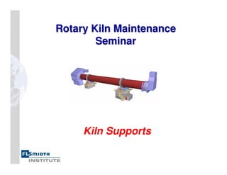
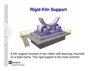
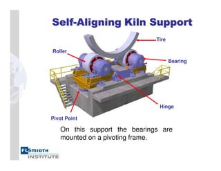
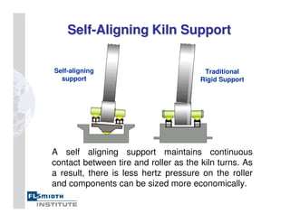
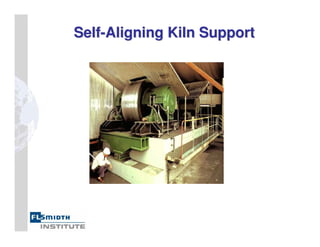
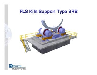
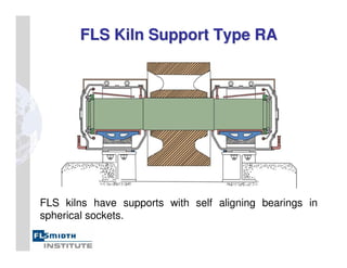
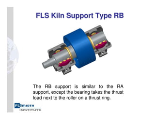
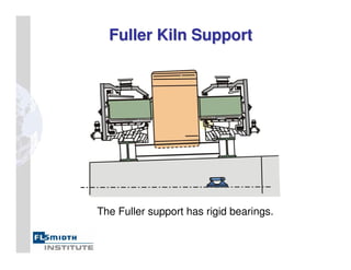
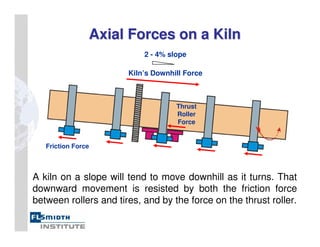
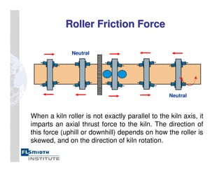
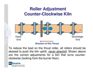
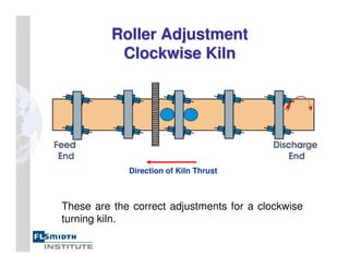
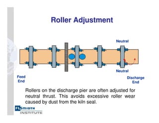
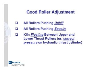
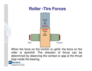
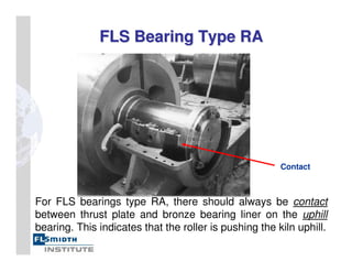
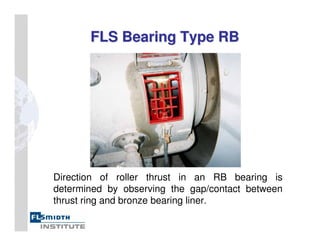
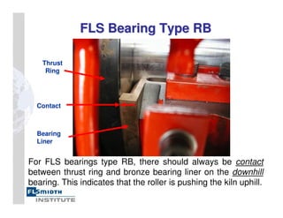
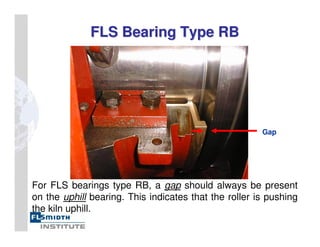
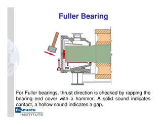
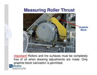
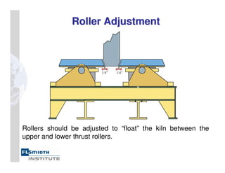
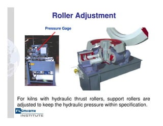
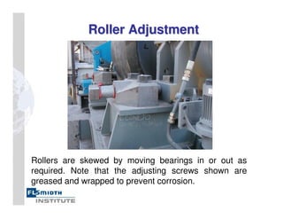
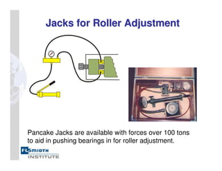
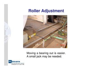
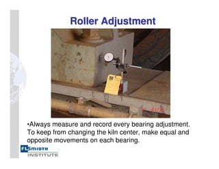
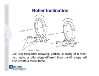
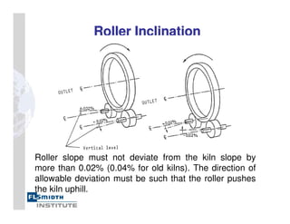
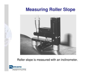
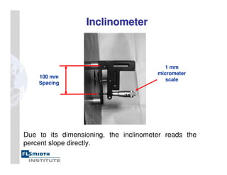
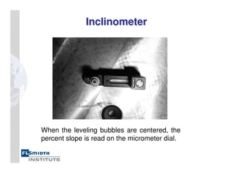
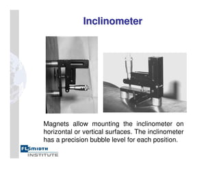
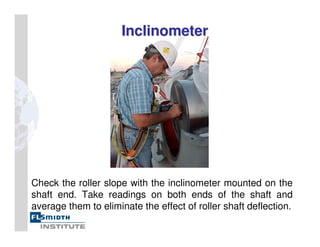
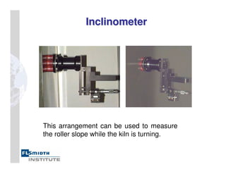
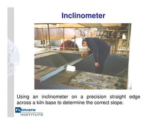
While rotary kilns are often engineered around the characteristics of the material to be processed, the base of a rotary kiln can be somewhat standard. This presentation looks at the construction and components of both indirect-fired and direct-fired rotary kilns.
Here you can see all about of bearings and thrust bearing. If you want
To know more information about its , then you feel free to visit web
Portal of tradeindia.
In this PPT you will learn about Bearings, Its Types, Classifications, Uses, How to select them according to use with proper and neat Diagrams and pictures.
,bearings ,function of bearing ,footstep or pivot bearing ,bush and direct-lined housing ,thrust bearing ,journal bearing ,ball and roller bearings ,types of rolling bearing ,sliding contact bearing ,applications of roller bearings
Our bearings rotate in the most demanding and efficient machines throughout Americas, Europe, Asia and Africa. We devised our corporate strategies considering global industrial trends and needs. We supply high-quality of various types of bearings from our manufacturing facilities in USA and Europe, to clients in over 40 countries.
Cosmetic shop management system project report.pdfKamal Acharya
Buying new cosmetic products is difficult. It can even be scary for those who have sensitive skin and are prone to skin trouble. The information needed to alleviate this problem is on the back of each product, but it's thought to interpret those ingredient lists unless you have a background in chemistry.
Instead of buying and hoping for the best, we can use data science to help us predict which products may be good fits for us. It includes various function programs to do the above mentioned tasks.
Data file handling has been effectively used in the program.
The automated cosmetic shop management system should deal with the automation of general workflow and administration process of the shop. The main processes of the system focus on customer's request where the system is able to search the most appropriate products and deliver it to the customers. It should help the employees to quickly identify the list of cosmetic product that have reached the minimum quantity and also keep a track of expired date for each cosmetic product. It should help the employees to find the rack number in which the product is placed.It is also Faster and more efficient way.
Water scarcity is the lack of fresh water resources to meet the standard water demand. There are two type of water scarcity. One is physical. The other is economic water scarcity.
Welcome to WIPAC Monthly the magazine brought to you by the LinkedIn Group Water Industry Process Automation & Control.
In this month's edition, along with this month's industry news to celebrate the 13 years since the group was created we have articles including
A case study of the used of Advanced Process Control at the Wastewater Treatment works at Lleida in Spain
A look back on an article on smart wastewater networks in order to see how the industry has measured up in the interim around the adoption of Digital Transformation in the Water Industry.
About
Indigenized remote control interface card suitable for MAFI system CCR equipment. Compatible for IDM8000 CCR. Backplane mounted serial and TCP/Ethernet communication module for CCR remote access. IDM 8000 CCR remote control on serial and TCP protocol.
• Remote control: Parallel or serial interface.
• Compatible with MAFI CCR system.
• Compatible with IDM8000 CCR.
• Compatible with Backplane mount serial communication.
• Compatible with commercial and Defence aviation CCR system.
• Remote control system for accessing CCR and allied system over serial or TCP.
• Indigenized local Support/presence in India.
• Easy in configuration using DIP switches.
Technical Specifications
Indigenized remote control interface card suitable for MAFI system CCR equipment. Compatible for IDM8000 CCR. Backplane mounted serial and TCP/Ethernet communication module for CCR remote access. IDM 8000 CCR remote control on serial and TCP protocol.
Key Features
Indigenized remote control interface card suitable for MAFI system CCR equipment. Compatible for IDM8000 CCR. Backplane mounted serial and TCP/Ethernet communication module for CCR remote access. IDM 8000 CCR remote control on serial and TCP protocol.
• Remote control: Parallel or serial interface
• Compatible with MAFI CCR system
• Copatiable with IDM8000 CCR
• Compatible with Backplane mount serial communication.
• Compatible with commercial and Defence aviation CCR system.
• Remote control system for accessing CCR and allied system over serial or TCP.
• Indigenized local Support/presence in India.
Application
• Remote control: Parallel or serial interface.
• Compatible with MAFI CCR system.
• Compatible with IDM8000 CCR.
• Compatible with Backplane mount serial communication.
• Compatible with commercial and Defence aviation CCR system.
• Remote control system for accessing CCR and allied system over serial or TCP.
• Indigenized local Support/presence in India.
• Easy in configuration using DIP switches.
Overview of the fundamental roles in Hydropower generation and the components involved in wider Electrical Engineering.
This paper presents the design and construction of hydroelectric dams from the hydrologist’s survey of the valley before construction, all aspects and involved disciplines, fluid dynamics, structural engineering, generation and mains frequency regulation to the very transmission of power through the network in the United Kingdom.
Author: Robbie Edward Sayers
Collaborators and co editors: Charlie Sims and Connor Healey.
(C) 2024 Robbie E. Sayers
4. Rigid Kiln Support
Rigid Kiln Support
A kiln support consists of two rollers with bearings mounted
on a base frame. This rigid support is the most common.
6. Self
Self-
-Aligning
Aligning Kiln Support
Kiln Support
A self aligning support maintains continuous
contact between tire and roller as the kiln turns. As
a result, there is less hertz pressure on the roller
and components can be sized more economically.
Self-aligning
support
Traditional
Rigid Support
9. FLS Kiln Support Type RA
FLS Kiln Support Type RA
FLS kilns have supports with self aligning bearings in
spherical sockets.
10. FLS Kiln Support Type RB
FLS Kiln Support Type RB
The RB support is similar to the RA
support, except the bearing takes the thrust
load next to the roller on a thrust ring.
13. Axial Forces on a Kiln
Axial Forces on a Kiln
A kiln on a slope will tend to move downhill as it turns. That
downward movement is resisted by both the friction force
between rollers and tires, and by the force on the thrust roller.
2 - 4% slope
Friction Force
Thrust
Roller
Force
Kiln’s Downhill Force
14. Roller Friction Force
Roller Friction Force
When a kiln roller is not exactly parallel to the kiln axis, it
imparts an axial thrust force to the kiln. The direction of
this force (uphill or downhill) depends on how the roller is
skewed, and on the direction of kiln rotation.
Neutral
Neutral
15. Roller Adjustment
Roller Adjustment
Counter
Counter-
-Clockwise Kiln
Clockwise Kiln
To reduce the load on the thrust roller, all rollers should be
skewed to push the kiln uphill, never downhill. Shown above
are the correct adjustments for a kiln that turns counter-
clockwise (looking from the burner floor).
Direction of Kiln Thrust
17. Roller Adjustment
Roller Adjustment
Rollers on the discharge pier are often adjusted for
neutral thrust. This avoids excessive roller wear
caused by dust from the kiln seal.
Neutral
Neutral
Feed
End
Discharge
End
18. Good Roller Adjustment
Good Roller Adjustment
All Rollers Pushing Uphill
All Rollers Pushing Equally
Kiln Floating Between Upper and
Lower Thrust Rollers (or, correct
pressure on hydraulic thrust cylinder)
19. Roller
Roller -
-Tire Forces
Tire Forces
When the force on the tire/kiln is uphill, the force on the
roller is downhill. The direction of thrust can be
determined by observing the contact or gap at the thrust
stop inside the bearing.
Direction of Kiln Thrust
20. Bearing Thrust Arrangements
Bearing Thrust Arrangements
FLS Type RA
Takes Thrust Load on Thrust Collar
FLS Type RB
Takes Thrust Load on Thrust Ring
Fuller
Takes Thrust Load on Thrust Washer
Uphill
Bearing
Downhill
Bearing
21. Bearing Thrust Arrangements
Bearing Thrust Arrangements
FLS Type RA
FLS Type RB
Fuller
Contact
Contact
Contact
Gap
Gap
Gap
Direction of
Force on Kiln
Direction of
Force on Roller
22. FLS Bearing Type RA
FLS Bearing Type RA
The RA bearing takes the thrust load on a thrust
plate which is bolted to the end of the shaft.
Thrust
Collar
26. Fuller Bearing
Fuller Bearing
The Fuller bearing takes the thrust load on a thrust
washer which is bolted onto to the housing end cover.
Thrust
Washer
27. FLS Bearing Type RA
FLS Bearing Type RA
The direction of roller thrust in an RA bearing is determined by
observing the gap between thrust plate and bronze bearing
liner. Contact in the uphill bearing and a gap in the lower
bearing indicates that the roller is pushing the kiln uphill.
28. FLS Bearing Type RA
FLS Bearing Type RA
For FLS bearings type RA, there should always be contact
between thrust plate and bronze bearing liner on the uphill
bearing. This indicates that the roller is pushing the kiln uphill.
Contact
29. FLS Bearing Type RB
FLS Bearing Type RB
Direction of roller thrust in an RB bearing is
determined by observing the gap/contact between
thrust ring and bronze bearing liner.
30. FLS Bearing Type RB
FLS Bearing Type RB
For FLS bearings type RB, there should always be contact
between thrust ring and bronze bearing liner on the downhill
bearing. This indicates that the roller is pushing the kiln uphill.
Contact
Thrust
Ring
Bearing
Liner
31. FLS Bearing Type RB
FLS Bearing Type RB
For FLS bearings type RB, a gap should always be present
on the uphill bearing. This indicates that the roller is pushing
the kiln uphill.
Gap
32. Fuller Bearing
Fuller Bearing
For Fuller bearings, thrust direction is checked by rapping the
bearing end cover with a hammer. A solid sound indicates
contact, a hollow sound indicates a gap.
33. Measuring Roller Thrust
Measuring Roller Thrust
Important! Rollers and tire surfaces must be completely
free of oil when skewing adjustments are made. Only
graphite block lubrication is permitted.
Graphite
Block
34. Rollers should be adjusted to “float” the kiln between the
upper and lower thrust rollers.
Roller Adjustment
Roller Adjustment
35. For kilns with hydraulic thrust rollers, support rollers are
adjusted to keep the hydraulic pressure within specification.
Pressure Gage
Roller Adjustment
Roller Adjustment
36. The force on the thrust roller can be calculated from the
hydraulic pressure indicated on the gage.
Hydraulic Pressure
Hydraulic Pressure
Force = Pressure x Area
Area = (Piston Diameter) 2 x
4
37. Calculation of Hydraulic Pressure
Calculation of Hydraulic Pressure
When All Rollers Are Neutral
• Calculate the weight of the rotating parts of the kiln (shell,
tires, gear, refractory, material load).
• Multiply by the % kiln slope to get the force on the thrust roller.
• Divide by the total piston area of all thrust rollers.
Example:
• 1000 short ton kiln x 2,000 pounds/short ton = 2,000,000 pounds
• 2,000,000 pounds x 3% slope = 60,000 pounds force on thrust roller
• Area of single 10” diameter piston = (10) 2 x = 78.5 inches 2
4
Pressure = 60,000 = 764 PSI
78.5
38. Roller Adjustment
Roller Adjustment
Rollers are skewed by moving bearings in or out as
required. Note that the adjusting screws shown are
greased and wrapped to prevent corrosion.
39. Jacks for Roller Adjustment
Jacks for Roller Adjustment
Pancake Jacks are available with forces over 100 tons
to aid in pushing bearings in for roller adjustment.
41. •Always measure and record every bearing adjustment.
To keep from changing the kiln center, make equal and
opposite movements on each bearing.
Roller Adjustment
Roller Adjustment
42. Measuring Roller Thrust
Measuring Roller Thrust
Measuring precise roller thrust is possible on FLS
bearings using this “axial measuring device”.
43. The axial measuring device consists of a hand jack with
pressure gage, a mounting fixture, and an adapter with
bearing to enable readings when the roller is turning.
Measuring Roller Thrust
44. Measuring Roller Thrust
Measuring Roller Thrust
The jack is pumped up until the roller begins to move
uphill off its thrust stop. At this point a pressure reading
is taken and the reading is then converted to tons force.
46. Measuring Roller Thrust
Measuring Roller Thrust
Caution! It may not be possible to accurately measure
roller thrust if tire and roller surfaces are not
cylindrical or if roller shafts or bearings are grooved.
Step-worn Roller and Tire Grooved Roller Shaft
47. Determining Roller Thrust
Determining Roller Thrust
Trial and Error Method
Find the roller’s neutral point (parallel to kiln axis)
by adjusting the roller skew in small increments
until the bearing thrust contact/gap changes from
one bearing to the other.
Once the neutral point is determined, make a
small adjustment to push the kiln uphill.
While making an adjustment of an individual roller,
always observe the kiln’s thrust rollers to ensure
that they are not being overloaded.
49. Roller Inclination
Roller Inclination
Just like horizontal skewing, vertical skewing of a roller,
i.e., having a roller slope different than the kiln slope, will
also create a thrust force.
50. Roller Inclination
Roller Inclination
Roller slope must not deviate from the kiln slope by
more than 0.02% (0.04% for old kilns). The direction of
allowable deviation must be such that the roller pushes
the kiln uphill.
55. Inclinometer
Inclinometer
Check the roller slope with the inclinometer mounted on the
shaft end. Take readings on both ends of the shaft and
average them to eliminate the effect of roller shaft deflection.
59. If kiln rollers are skewed too much the
wear rate can be quite severe.
Tire and Roller Defects
60. Excessive hertz pressures on under-designed or poorly
cast tires and rollers can result in severe pitting.
Tire and Roller Defects
61. The old practice of running a roller in a water bath is now
thought to promote surface pitting and is no longer
recommended.
Tire and Roller Defects
62. Tire and Roller Defects
Tire and Roller Defects
When rollers are misaligned or conical-shaped, the kiln
load is spread over too small an area. This causes high
surface stresses resulting in pitting.
63. Tire and Roller Defects
Tire and Roller Defects
A defect on a roller may transfer
to the tire, and vice-versa.
64. Tire and Roller Defects
Tire and Roller Defects
Roller or tires may wear to a conical shape.
65. Tire and Roller Defects
Tire and Roller Defects
A tire running off the roller for a long time will wear
into a step pattern.
66. Tire and Roller Defects
Tire and Roller Defects
Tire wobble can create a concave roller surface.
67. Roller and Tire Re
Roller and Tire Re-
-conditioning
conditioning
68. Roller and Tire Re
Roller and Tire Re-
-conditioning
conditioning
Rollers and tires may be re-conditioned by machining or
grinding. Shown above is a lathe adapted for this purpose.
69. Roller and Tire Re
Roller and Tire Re-
-conditioning
conditioning
Rollers are re-conditioned while the kiln is in operation.
70. Roller and Tire Re
Roller and Tire Re-
-conditioning
conditioning
Machining a kiln tire while the kiln is in operation.
71. Roller and Tire Re
Roller and Tire Re-
-conditioning
conditioning
The machinist is protected with a heat shield.
72. Roller and Tire Re
Roller and Tire Re-
-conditioning
conditioning
This roller is being resurfaced by grinding rather
than machining.
73. Roller and Tire Re
Roller and Tire Re-
-conditioning
conditioning
Re-surfacing a tire by grinding
74. Tire and roller edge defects must also be
removed. Edges should then be chamfered.
Roller and Tire Re
Roller and Tire Re-
-conditioning
conditioning