
Recommended
More Related Content
What's hot
What's hot (8)
Similar to ETAP - Creating an old
Similar to ETAP - Creating an old (20)
Recently uploaded
Recently uploaded (20)
ETAP - Creating an old
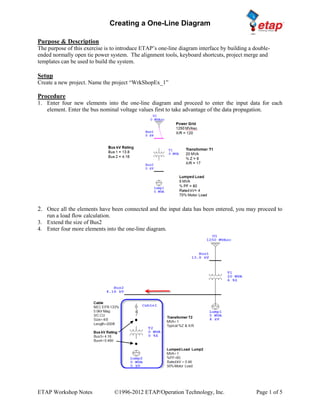
- 1. Creating a One-Line Diagram ETAP Workshop Notes ©1996-2012 ETAP/Operation Technology, Inc. Page 1 of 5 Purpose & Description The purpose of this exercise is to introduce ETAP’s one-line diagram interface by building a double- ended normally open tie power system. The alignment tools, keyboard shortcuts, project merge and templates can be used to build the system. Setup Create a new project. Name the project “WrkShopEx_1” Procedure 1. Enter four new elements into the one-line diagram and proceed to enter the input data for each element. Enter the bus nominal voltage values first to take advantage of the data propagation. 2. Once all the elements have been connected and the input data has been entered, you may proceed to run a load flow calculation. 3. Extend the size of Bus2 4. Enter four more elements into the one-line diagram.
- 2. Creating a One-Line Diagram ETAP Workshop Notes ©1996-2012 ETAP/Operation Technology, Inc. Page 2 of 5 5. Proceed to connect them and enter the required data. 6. Once all the elements have been connected and the input data has been entered, you may proceed to run a load flow calculation. 7. Extend the length of Bus2 towards the right side. 8. Drop a Generator on the one-line and rotate Gen1 by 180o using <CONTROL+R> 9. Once the Generator has been connected and the input data has been entered, you may proceed to run a Load Flow Calculation. 10. Extend the length of Bus1 towards the right side. 11. Copy elements T1, Bus2, Lump1, Cable1, T2, Bus4, Bus3 (node between Cable1 & T2) and Lump2. 12. Move elements from Dumpster (using right click on mouse) and connect them to Bus1. 13. Make sure to ungroup the elements (right click after highlighting the elements). 14. Insert a normally open Tie Breaker between Bus4 and Bus5. 15. Rubber band both branches connected to Bus2 and Bus7. 16. Cut all the highlighted elements.
- 3. Creating a One-Line Diagram ETAP Workshop Notes ©1996-2012 ETAP/Operation Technology, Inc. Page 3 of 5 17. Insert a Composite Network and connect between Bus2 and Bus7. 18. Open the Composite Network and move the elements from the dumpster using right click on your mouse. Select Move from Dumpster into composite Network1 window. 19. Connect the cables to the pins that show the Bus ID originally connected to. 20. Insert High Voltage Circuit Breakers on the indicated locations as seen below. 21. Insert Low Voltage Circuit Breakers inside the Composite network and place them before the Lumped Loads.
- 4. Creating a One-Line Diagram ETAP Workshop Notes ©1996-2012 ETAP/Operation Technology, Inc. Page 4 of 5 Results after running Load Flow
- 5. Creating a One-Line Diagram ETAP Workshop Notes ©1996-2012 ETAP/Operation Technology, Inc. Page 5 of 5 22. Highlight the entire one line diagram by rubber banding with your mouse. 23. Select to add to OLV Template to save your one line diagram as an xml for future use. 24. Name it WrkShopEx_1 and view using the Get Template icon . 25. Any template can be brought into an existing or new project for versions after ETAP 7.0.0.