Downloaded 27 times
![Technical Note
TN.013.D20150915 TN013 ESD Failure Analysis of PV Module Diodes and TLP Test Method
By Wei Huang and Jerry Tichenor
Page 1
ESDEMC Technology LLC, 4000 Enterprise Dr, Suite 103, Rolla, MO, 65409, USA
www.esdemc.com Tel: (+1)-573-202-6411 Fax: (+1) 877-641-9358 Email: info@esdemc.com
ESD Failure Analysis of PV Module Diodes
and TLP Test Method
`
1. Introduction
Bypass diodes inserted across the strings of the solar panel arrays are essential to ensure the
efficiency of the solar power system. However, those diodes are found to be susceptible to potential
Electrostatic Discharge (ESD) events in the process of solar Photovoltaic (PV) panel manufacture,
transportation and on-site installation. Please refer [1], where an International PV Module Quality
Assurance Forum has been setup to investigate PV Module reliability, and Task Force 4 has been setting
guidelines for testing the ESD robustness of diodes used to enhance PV panel performance. This
document explains the theory behind the ESD damage and the proper test and analysis methods for ESD
failure of diodes. To demonstrate the proposed testing methodology that follows, we will be evaluating
six different types of diode models as supplied by our customer, who manufactures solar panel arrays.
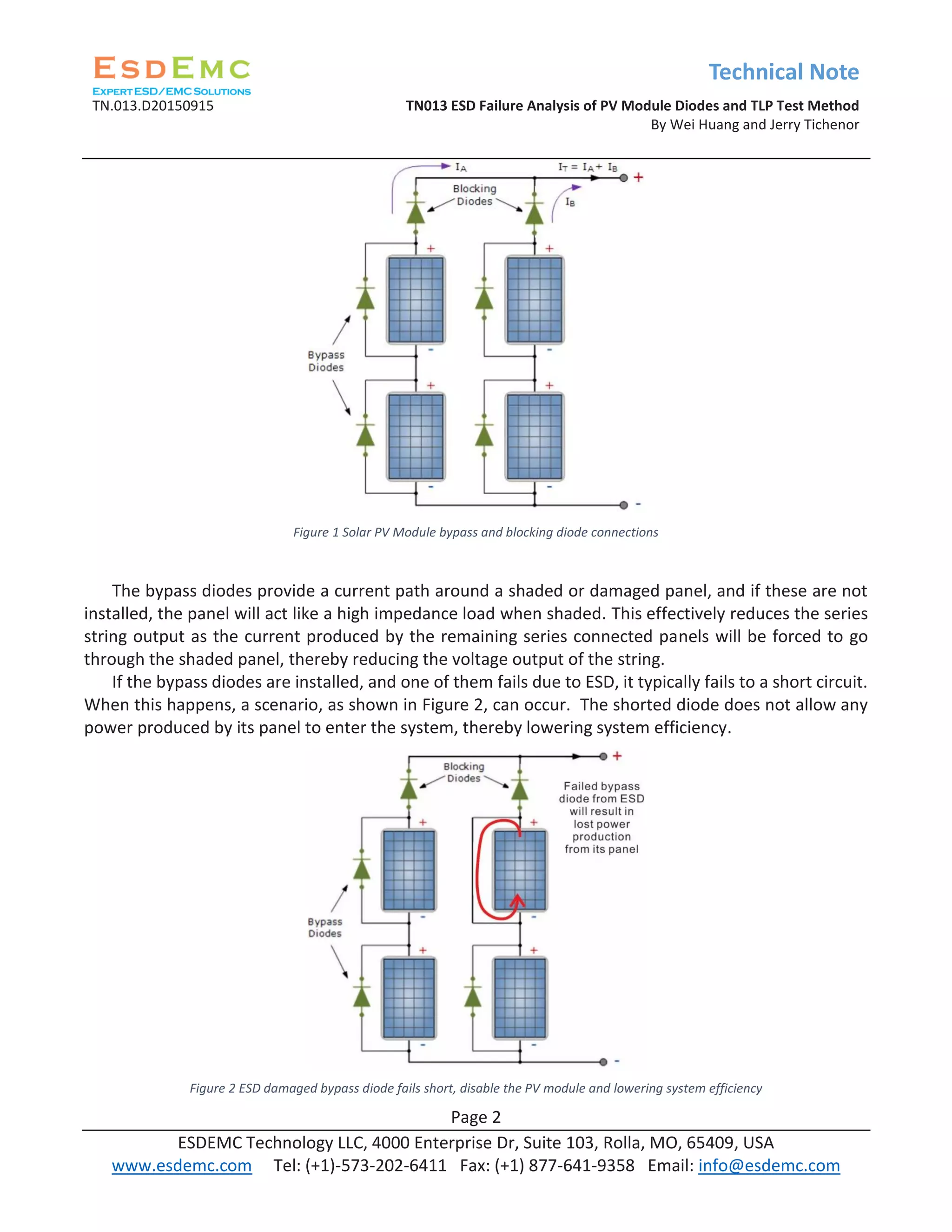
1.1 Bypass and Blocking Diodes in Solar Panel Arrays
To help maintain the efficiency and performance of solar panel arrays it is common for bypass diodes
to be inserted across individual PV panels, and blocking diodes to be inserted in series with a string of
panels that are used in a parallel array. Figure 1 demonstrates how these diodes are inserted into a panel
array [2].
How could ESD damage happened?
What is Cable Discharge Event?
What is Transmission Line Pulse test?](https://image.slidesharecdn.com/esdemctn013esdfailureanalysisofpvmodulediodes-150926182335-lva1-app6892/75/TN013-ESD-Failure-Analysis-of-PV-Module-Diodes-and-TLP-Test-Method-1-2048.jpg)
![Technical Note
TN.013.D20150915 TN013 ESD Failure Analysis of PV Module Diodes and TLP Test Method
By Wei Huang and Jerry Tichenor
Page 3
ESDEMC Technology LLC, 4000 Enterprise Dr, Suite 103, Rolla, MO, 65409, USA
www.esdemc.com Tel: (+1)-573-202-6411 Fax: (+1) 877-641-9358 Email: info@esdemc.com
Figure 3 ESD damaged blocking diode fails short, allowing battery discharge path at night
Blocking diodes keep current from the battery pack, or a parallel panel string from entering a
damaged string. This is important at night when the panel array cannot provide any power, thus
providing a path for the battery to discharge. When installed, the blocking diodes may have leakage
current on the order of nano- or micro-amps. However, if they fail due to ESD, they typically fail to a
short circuit providing another path for the battery to discharge. This discharge current can be milli-amps
or amps. An example of this failure scenario is shown in Figure 3.
Failure of even one of these diodes in the field is very expensive for companies to replace due to
the need for a qualified service technician, as most installations will require code requirements to be
met. Continued operation of the panel array with a damaged bypass or blocking diode will, at best,
hamper the array’s efficiency and, at worst, cause permanent damage as it consumes power rather than
produces power. It has been proposed that the damage to the diodes is caused by electrostatic discharge
(ESD) stress.
1.2 What is ESD and how it damage the solar PV module diodes
Electrostatic discharge is the sudden flow of electricity between two electrically charged objects
caused by contact, an electrical short, or dielectric breakdown [3]. Electrostatic discharge stress can
occur in many forms and, depending on the characteristics of the stress, can damage different parts of
solar PV module subjected to the stress. In particular, there are several ESD models with industrial
standards that describe the pulse shape, source impedance, and determines levels at which the device
should survive.
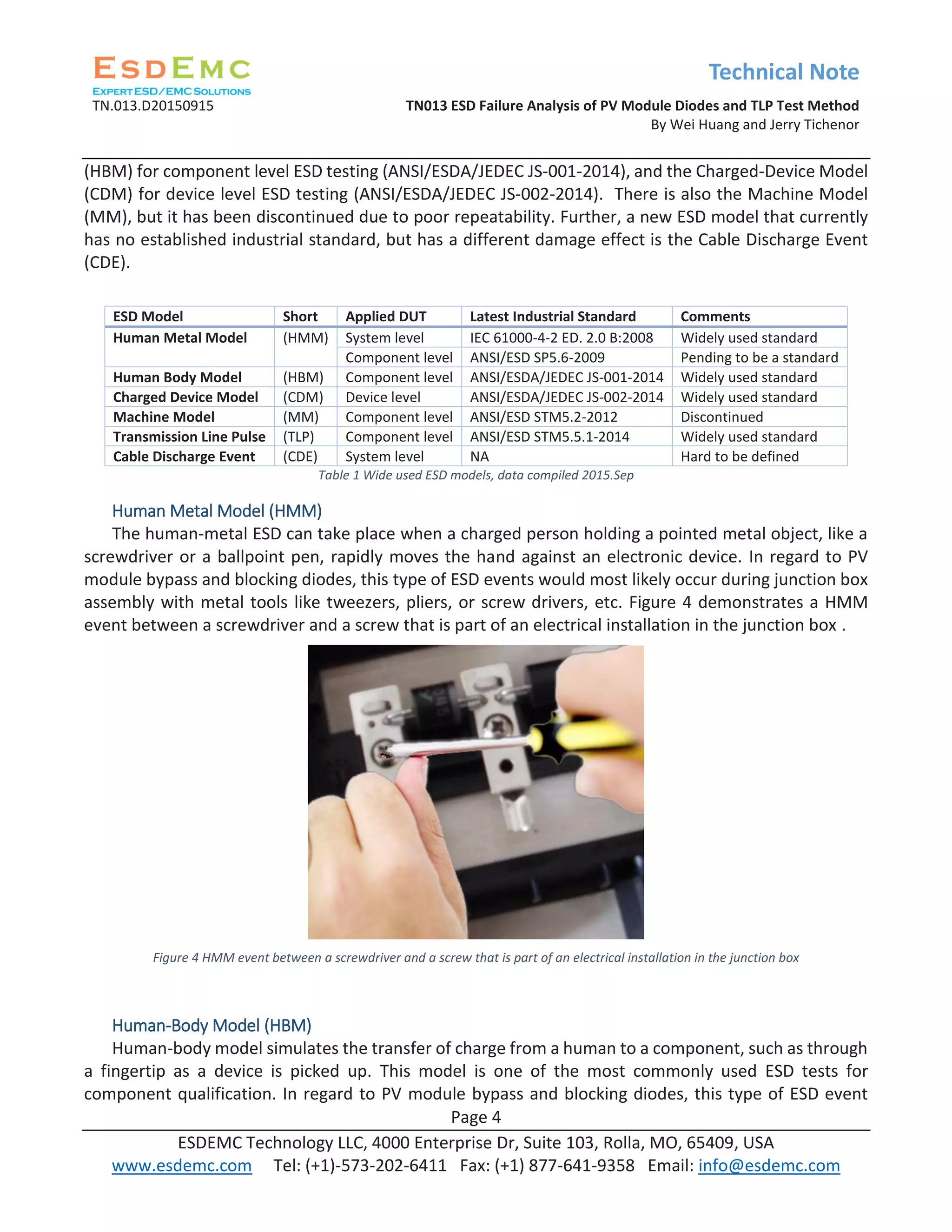
The commonly used ESD models are the Human-Metal Model (HMM) (IEC 61000-4-2 for system
level ESD testing or ANSI/ESD SP5.6-2009 for component level ESD testing), the Human-Body Model](https://image.slidesharecdn.com/esdemctn013esdfailureanalysisofpvmodulediodes-150926182335-lva1-app6892/75/TN013-ESD-Failure-Analysis-of-PV-Module-Diodes-and-TLP-Test-Method-3-2048.jpg)
![Technical Note
TN.013.D20150915 TN013 ESD Failure Analysis of PV Module Diodes and TLP Test Method
By Wei Huang and Jerry Tichenor
Page 5
ESDEMC Technology LLC, 4000 Enterprise Dr, Suite 103, Rolla, MO, 65409, USA
www.esdemc.com Tel: (+1)-573-202-6411 Fax: (+1) 877-641-9358 Email: info@esdemc.com
would also most likely occur during junction box assembly, especially if the operator picks a diode and
mounts it by hand into the junction box. Figure 5 demonstrates a personnel picking up a PV module
diode with bare fingers.
Figure 5 Potential ESD from HBM, Picking up the diodes
Charged-Device Model (CDM)
Charged-device model simulates the transfer of charge from a device to ground. A device can collect
charge by sliding across a surface and then discharged by contact to a metal surface or ground [6]. In
regard to PV module bypass and blocking diodes, this type of ESD event would most likely occur during
junction box assembly.
Figure 6 Solar PV module diode drops onto grounded metal surface
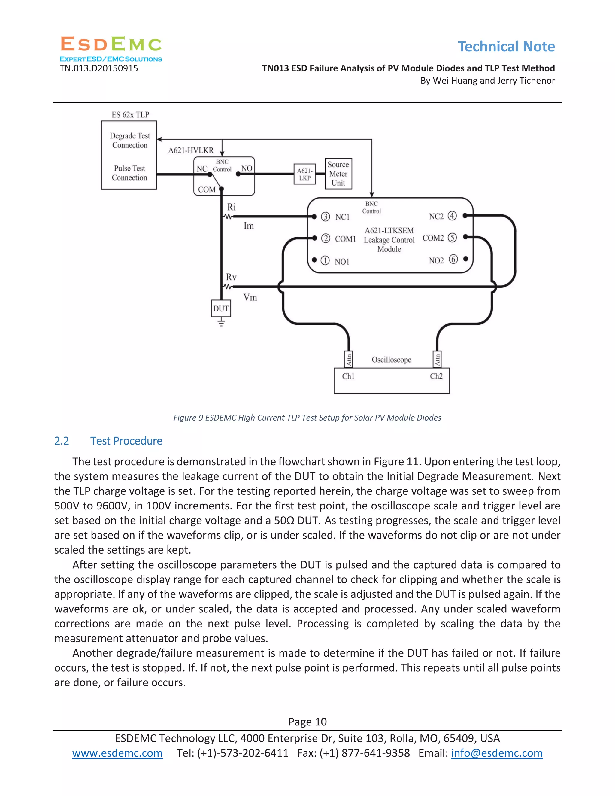
Transmission Line Pulse (TLP)
The TLP technique is based on charging a transmission line to a pre-determined voltage, and
discharging it into a DUT. The cable discharge emulates an electro-static discharge event that has better
defined RF signal path, controllable rise-time, and pulse width. The test setup allows transient current
and voltage waveform to be monitored therefore the change of the DUT impedance can be monitored
as a function of time in ps details. The DUT performance degrade or failure check can be automated with
RF high voltage switch and help the system with faster ESD performance analysis. Regarding to the PV](https://image.slidesharecdn.com/esdemctn013esdfailureanalysisofpvmodulediodes-150926182335-lva1-app6892/75/TN013-ESD-Failure-Analysis-of-PV-Module-Diodes-and-TLP-Test-Method-5-2048.jpg)


![Technical Note
TN.013.D20150915 TN013 ESD Failure Analysis of PV Module Diodes and TLP Test Method
By Wei Huang and Jerry Tichenor
Page 12
ESDEMC Technology LLC, 4000 Enterprise Dr, Suite 103, Rolla, MO, 65409, USA
www.esdemc.com Tel: (+1)-573-202-6411 Fax: (+1) 877-641-9358 Email: info@esdemc.com
3. ESDEMC Solar PV Module Diodes Test
Over the years, ESDEMC Technology has tested several diode models for solar PV module companies.
The Maximum Peak Repetitive Reverse Voltage (VRRM) of the diodes are listed in Table 3Table 1. The
VRRM values are important because they provide the maximum bias voltage applied to the diode for
leakage current measurement. This value is supplied by the device manufacturer, and can be found in
their respective datasheets.
Equipment Brand and Model Specification and Comments
ESD Test ES621-200 TLP System
(A specially developed
system, not a release
model. The ES620-200
model may be released
for a simplified turnkey
solution)
<=1 ns rise-time, 100 ns pulse width, Max 10 kV charge line with no reflection
rejection.
The 10 kV charge voltage is achievable in the real world under dry conditions.
The 100 ns pulse is represented approximately 10 meters of cable that is very
close to the grounding conduit. Please note that during installation, a charged
PV module connecting to a grounded cable will have the same effect as a
charged cable discharging to a PV module. A 10 meter cable may not be the
worst case since solar cables could be up to hundreds meters for certain
systems.
Failure Test Keithley Model 2400 or
Keithley Model 6487
This configuration depends on the diode VRRM
Oscilloscope Agilent DSO9204H 2 GHz, 10 Gs/s
(200 MHz min bandwidth per ANSI/ESD STM5.5.1-2014 standard)
Table 2 ESDEMC Solar PV Module Diodes TLP Test Equipment and Settings
Diode Model VRRM, [V]
HY25PV060 60
HY25PV050 50
Vishay VSB1545 45
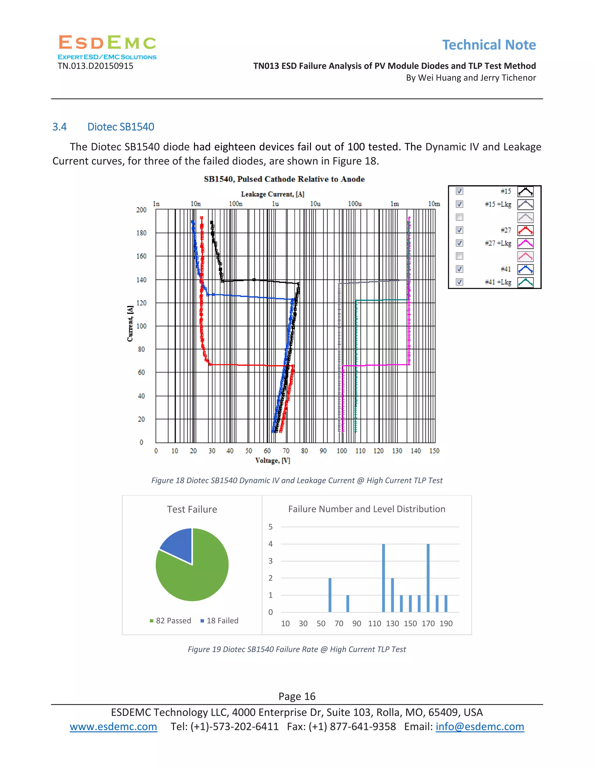
Diotec SB1540 40
Tyco F1200DC 150
Diotec F1200D 200
Table 3 Diode models tested and their VRRM
In the following sections, the test results will be presented in terms of the best performer to the
worst performer in regard to diode failure during TLP testing.](https://image.slidesharecdn.com/esdemctn013esdfailureanalysisofpvmodulediodes-150926182335-lva1-app6892/75/TN013-ESD-Failure-Analysis-of-PV-Module-Diodes-and-TLP-Test-Method-12-2048.jpg)


![Technical Note
TN.013.D20150915 TN013 ESD Failure Analysis of PV Module Diodes and TLP Test Method
By Wei Huang and Jerry Tichenor
Page 20
ESDEMC Technology LLC, 4000 Enterprise Dr, Suite 103, Rolla, MO, 65409, USA
www.esdemc.com Tel: (+1)-573-202-6411 Fax: (+1) 877-641-9358 Email: info@esdemc.com
Of the diodes tested the Vishay VSB2045 and Hornby 15SQ050 are the only models that are Schottky
Barrier type. However, as the data suggests, the Schottky Barrier type does not necessarily guarantee
better performance in regard to withstanding ESD stress.
It has been suggested that it is not necessarily the diode design type that determines if the diode is
more or less susceptible to ESD stress, but instead a result of quality control of the manufacturing. For
example, the process may be as follows: a diode as the 15SQ100 (not tested herein) is being checked in
quality control after manufacturing. Its reverse breakdown voltage is checked. If it does not pass 100V,
but passes 50V, it is re-labeled as a 15SQ050 model. This may not guarantee that the 15SQ050 model is
a high quality 050 design, and may instead be a poor quality 100 design relegated to the 050 model line.
Here, the problem is that the diode may not hold 100V reverse voltage due to a local defect. The local
defect will concentrate the current during ESD into a very small area and cause the diode locally to melt.
Thus, the robustness of such a diode is much worse than a diode that passes the 100V reverse voltage,
which may indicate that it does have few, and less severe local defects.
According to our customer, our findings on the diode failure rate, through TLP test methodology,
correlates to their field return failure rate. Therefore, we recommend that TLP testing be performed for
all solar PV module diodes. In addition, it may be in the best interest of both solar PV module and diode
manufacturers to investigate the quality control of the diodes selected, yielding a more reliable design
for field use.
References
[1] International PV Module Quality Assurance Forum, Task Force 4 (www.pvqat.org), Dec. 5-7,
2011.
[2] n.a., (2015, Sept. 8), Bypass Diodes, Retrieved from http://www.electronics-
tutorials.ws/diode/bypass-diodes.html.
[3] n.a., Electrostatic Discharge, Retrieved from
https://en.wikipedia.org/wiki/Electrostatic_discharge
[5] n.a., n.d., Part 5: Device Sensitivity and Testing, Retrieved from https://www.esda.org/about-
esd/esd-fundamentals/part-5-device-sensitivity-and-testing/
[6] n.a., n.d., CAB Products, Retrieved from http://www.cabproducts.com/cable-rings-solar/](https://image.slidesharecdn.com/esdemctn013esdfailureanalysisofpvmodulediodes-150926182335-lva1-app6892/75/TN013-ESD-Failure-Analysis-of-PV-Module-Diodes-and-TLP-Test-Method-20-2048.jpg)

The document discusses electrostatic discharge (ESD) failure analysis of bypass and blocking diodes in solar photovoltaic (PV) modules, highlighting their vulnerability during manufacturing, transportation, and installation. It details various ESD testing models like the human-metal model and the transmission line pulse test method, proposing the latter for better characterization of diode performance under ESD conditions. Failure of these diodes due to ESD can significantly diminish solar panel efficiency, necessitating effective testing methodologies to ensure reliability.


