SlideShare a Scribd company logo
B Defined by Equation (13), Chapter 7 - -
C Coefficient, defined by Equation (14), Chapter 7 W/m3
K Btu/ft2
F
Cp Specific heat J/kg K Btu/lb F
dh Hydraulic diameter of passage m ft
f Fanning friction factor - -
F Force N lb
Gm Mass flux/velocity of a stream kg/m2
s lb/ft2
hr
h Fin height mm in
H Stacking height of a core mm in
j Colburn factor for a finned passage - -
K Expansion/contraction/turning loss coefficient - -
lp Passage length mm in
L Core length mm in
LMTD Logarithmic mean temperature difference K F
M Moment Nm lb ft
MTD Mean temperature difference K F
p Fin pitch mm in
Pr Prandtl number - -
Q Overall heat duty; heat to be transferred W Btu
r Fouling resistance m2
K/W ft2
F hr/Btu
s Distance between the extreme bolts in a given plane mm in
t Fin thickness mm in
U Overall heat transfer coefficient between streams W/m2
K Btuhr ft2
F
W Width of core mm in
X Required clearance distance mm in
Greek
l Coefficient of linear expansion at average temperature m/m K ft/ft F
o Effective heat transfer coefficient of a stream W/m2
K Btuhr ft2
F
 Heat transfer coefficient of a stream W/m2
K Btuhr ft2
F
 Defined by Equation (11), Chapter 7 - -
 Defined by Equation (12), Chapter 7 - -
P Overall pressure drop N/m2
(Pa) lb/in2
TR Temperature range at support K F
1 Passage fin efficiency for single banking - -
2 Passage fin efficiency for double banking - -
m Thermal conductivity of fin material W/m K Btuhr ft F
 Density of stream kg/m3
lb/ft3
 Unperforated fraction of fin - -
Notation
Notation
SI IMPERIAL
A Effective heat transfer surface of a passage or layer m2
ft2
Ad Designed or estimated overall effective heat transfer surface m2
ft2
Ar Required overall effective heat transfer surface m2
ft2
A1 Primary heat transfer surface of a stream m2
ft2
A2 Secondary heat transfer surface of a stream m2
ft2
ls Serration length or distance between crests on herringbone fins mm in
n Fin density m-1
in-1
V Volume of heat exchanger or exchangers m3
ft3
T Local temperature difference between warm and cold streams K F
Subscripts
c Cold stream w Warm stream
i Section x,y,z Direction
STANDARDS OF THE BRAZED ALUMINIUM PLATE-FIN HEAT EXCHANGER MANUFACTURER'S ASSOCIATION  63
References
References
(1) Ward, J.A., "Effectiveness-NTU Relationships", Data Item 86018, Engineering Sciences Data
Unit, London, 1986.
(2) Kays, W.M. and London, A.L., "Compact Heat Exchangers", McGraw Hill, New York, Third
Edition, 1984.
(3) Taborek, J. and Spalding, D.B., "Heat Exchanger Design Handbook", Hemisphere Publishing
Corporation, 1983.
(4) Taylor, M.A., "Plate-Fin Heat Exchangers - Guide to Their Specification and Use", HTFS, 392.7
Harwell, Oxon, OX11 0RA, UK. 1987.
STANDARDS OF THE BRAZED ALUMINIUM PLATE-FIN HEAT EXCHANGER MANUFACTURER'S ASSOCIATION  65
Index
Index
Acceptable Fluids ...........................................2
AD-Merkblätter .............................................35
Aftercooler ......................................................2
Air Separation Unit(ASU)................................2
Air test ..........................................................36
Ammonia .................................................... 2, 3
Angle Bracket Support Arrangement ............ 26
Argon...............................................................3
AS 1210........................................................35
ASME VIll, Div. 1 ..........................................35
Asphyxiation .................................................32
Atmospheric Corrosion .................................62
Banking
Multiple .....................................................46
Single........................................................46
Beams
Support .....................................................23
Block (core) ....................................................4
Blocking of Layers ........................................22
Burst test method..........................................41
Butane .............................................................3
Cap sheet .......................................................4
Cap Sheets...................................................41
Carbon Dioxide........................................... 2, 3
Carbon Monoxide ....................................... 2, 3
Cascade Cooling...............................................3
Chillers ...........................................................2
Chlorine..........................................................2
Choice of Fin Geometry................................54
Cleaning ................................................. 20, 59
Solvent......................................................59
CODAP.........................................................35
Code Data Reports.......................................19
Codes for Construction .................................35
Coefficient of Thermal Expansion ................. 28
Colburn Factor..............................................50
Cold Boxes ...................................................32
Components
of an Exchanger..........................................4
of Manifolded Exchangers...........................5
Condenser
Overhead ....................................................2
Condensers ....................................................2
Connection Options
Flanges.......................................................6
Stub Ends ...................................................6
Transition Joints..........................................6
CONTRACTUAL INFORMATION................. 17
Cool-down ....................................................31
Core (block)....................................................4
Core Volume
Estimation .................................................52
Corrosion ......................................................60
Acidic Environments..................................61
Alkaline Environments...............................61
Atmospheric or Environmental...................62
Environments containing Mercury..............61
Water ........................................................60
Corrosion Allowances ...................................38
Damage........................................................33
Definition.......................................................35
Dephlegmators ...............................................2
Deplugging....................................................60
Description
General .......................................................1
DESIGN
HYDRAULIC .......................................45–55
THERMAL ...........................................45–55
Design Code.................................................17
Design Pressures..........................................35
Design Temperature .....................................37
Distributor
Central ......................................................10
Diagonal....................................................10
Double Entry/Exit.......................................10
End..............................................................9
Intermediate ................................................9
Mitre..........................................................10
Side.............................................................9
Special ........................................................9
Split Flow...................................................10
Distributor fins.................................................4
Drawings.......................................................18
Approval and Change................................18
for Record .................................................18
Information ................................................18
Proprietary Rights......................................19
Drying ...........................................................20
Dummy Passages.........................................20
Dutch Pressure Vessel Code ........................35
Ethane .............................................................3
Ethylene...........................................................3
Exchanger
block (core) .................................................1
cap sheets...................................................1
inlet ports.....................................................1
layers (passages) ........................................1
multi-stream ................................................1
outlet ports ..................................................1
parting sheets..............................................1
side bars......................................................1
size..............................................................1
FABRICATION........................................17–22
Failure Mechanism........................................57
STANDARDS OF THE BRAZED ALUMINIUM PLATE-FIN HEAT EXCHANGER MANUFACTURER'S ASSOCIATION  67
Index
Field Testing................................................. 29
Filters ........................................................... 31
Fin Corrugations............................................. 8
Fin Dimensions............................................... 9
Definition..................................................... 9
Fins Per Inch (FPI)...................................... 9
Percentage Perforation ............................... 9
Fin Geometry
Choice of................................................... 54
Fin Types........................................................ 8
Fins .............................................................. 41
Herringbone................................................ 8
Perforated................................................... 8
Plain............................................................ 8
Serrated...................................................... 8
Wavy........................................................... 8
Fixing Bolts................................................... 27
Flange Protection ......................................... 20
Flanges ........................................................ 40
Flow Arrangements ...................................... 11
Co-Current Flow........................................ 11
Counterflow............................................... 11
Cross-Counterflow .................................... 11
Crossflow.................................................. 11
Flow Fluctuations.......................................... 57
Flow Velocities in Nozzles ............................ 39
Fluids
Acceptable.................................................. 2
Fouling ......................................................... 58
Fouling Resistance....................................... 51
Freeze Spots................................................ 32
Freon............................................................... 3
General Description........................................ 1
GENERAL DESCRIPTION....................... 1–11
GOOD PRACTICE ................................. 57–62
Guarantees................................................... 19
Consequential Damage............................. 19
Corrosion .................................................. 19
Thermal and Mechanical........................... 19
Guide Frame
Sliding....................................................... 24
Handling ....................................................... 23
Header
Dome.......................................................... 7
Inclined Ends .............................................. 7
Mitred Ends................................................. 7
Standard ..................................................... 7
Header/Nozzle Configurations........................ 6
Headers.......................................... 4, 6, 38, 41
Heat Transfer Coefficient of a Stream........... 50
Heat transfer fins ............................................ 4
Heat Transfer Surface .................................. 47
Height............................................................. 4
Stacking...................................................... 1
Helium ............................................................. 3
Helium Leak Test.......................................... 34
Helium Recovery...............................................3
Helium test....................................................36
Hexane ............................................................3
HYDRAULIC DESIGN ............................45–55
Hydrogen .........................................................3
Hydrogen Sulphide .........................................2
Inactive Areas...............................................20
Injury.............................................................33
Inspection .....................................................17
Manufacturer’s ..........................................17
Purchaser’s ...............................................17
Third Party ................................................17
INSTALLATION ......................................23–34
Insulation ......................................................30
Japanese HPGS Law....................................35
Layer Arrangements .....................................40
Leak Detection..............................................32
Leak Rate .....................................................37
Leak Test......................................................36
Air .............................................................36
Helium.......................................................36
Length ............................................................4
Lifting............................................................23
Lifting Devices ..............................................21
Lifting lugs ....................................................21
Limits of Use
Maximum working pressure.........................2
Maximum working temperature ...................2
Minimum design temperature......................2
Liquefaction ......................................................3
Liquefied Natural Gas ........................................3
Liquefied Natural Gas (LNG)...............................3
Liquefied Petroleum Gas (LPG)...........................3
Liquefiers........................................................2
Liquified Natural Gas (LNG)............................2
Logarithmic Mean Temperature Difference...50
Main Exchanger..............................................2
Maintenance .................................................32
MAINTENANCE......................................23–34
MATERIALS ...........................................43–44
Materials of Construction ........................35, 43
Mean Temperature Difference ......................47
MECHANICAL STANDARDS ................. 35–42
Mercury.....................................................3, 61
Metal Temperature Limitations......................37
Methane...........................................................3
Module Construction.......................................6
Mounting Bolts..............................................27
MTBE ..............................................................3
Multi-Component Refrigerants...........................3
Multiple Banking ...........................................46
Multi-Stream .................................................46
Nameplate ....................................................17
Data ..........................................................18
Manufacturer’s ..........................................17
Purchaser’s ...............................................18
68  STANDARDS OF THE BRAZED ALUMINIUM PLATE-FIN HEAT EXCHANGER MANUFACTURER'S ASSOCIATION
Structure ...................................................17
Supplementary Information .......................18
Natural Gas Processing (NGP)...................2, 3
Nitrogen ...........................................................3
Nitrogen Dioxide .............................................2
Nitrogen Rejection Unit (NRU) ............................3
NOMENCLATURE.................................... 1–11
Nomenclature of the Components ..................4
Nonconformity Rectification ..........................21
Non-Destructive Testing ...............................29
Nozzle
Inclined .......................................................7
Radial..........................................................7
Tangential ...................................................7
Nozzle loadings ............................................39
Nozzle Type....................................................6
Nozzles........................................... 4, 6, 39, 41
Flow Velocities in ......................................39
Loadings ...................................................39
Operation......................................................31
OPERATION .......................................... 23–34
Overall Heat Transfer ...................................47
Overhead Condenser .....................................2
Oxygen ............................................................3
Particulate Matter..........................................31
Parting sheet ..................................................4
Parting Sheets..............................................41
Pentane ...........................................................3
Petrochemical Production...................................3
Piping .............................................................6
Plant Upsets .................................................57
Plugging ................................................. 58, 59
from dust ..................................................... 3
from molecular sieve dust ...........................3
from particulates..........................................3
Pressure Loss...............................................52
Single-Phase.............................................53
Two-Phase................................................54
Pressure Relief Device .................................31
Pressure Relieving Devices..........................31
Pressure Test ......................................... 33, 36
Hydrostatic................................................36
Pneumatic.................................................36
Pressure Testing ..........................................29
Pressure Vessel ...........................................41
Pressurising..................................................20
Primary Heat Transfer Surface ..................... 45
Production Process.......................................40
Proof Pressure Testing .................................29
Propane ...........................................................3
Propylene.........................................................3
Pulsing..........................................................31
Raccolta .......................................................35
Rare Gases ......................................................3
Reboilers ........................................................2
Rectification
Index
Leak ..........................................................22
Nonconformity ...........................................21
Rectification of Leaks....................................22
Refrigeration Systems........................................3
Repair of Leaks.............................................34
Reversing Exchanger......................................2
Safety ...........................................................33
Scope of Supply............................................20
Secondary Heat Transfer Surface.................45
Services..........................................................2
Shear Plate Support Arrangement ................25
Shipment.......................................................19
Shop Operation.............................................17
Shut-down.....................................................32
Side bars...................................................4, 41
Single Banking..............................................46
Single-Phase Pressure Loss.........................53
Site leak Detection........................................33
Sliding Guide Frame .....................................24
Solvent Injection System...............................59
Spare parts ...................................................21
Special Features...........................................42
Specification Sheets ...............................47–49
Stacking Arrangement...................................55
Stacking height ...............................................1
Standard Sizes .............................................38
Cap Sheets ...............................................38
Fins ...........................................................38
Parting Sheets...........................................38
Side Bars...................................................38
STANDARDS
MECHANICAL.....................................35–42
Start-up.........................................................31
Subcooler Reboiler .........................................2
Sulphur Dioxide...............................................2
Supply
Scope of....................................................20
Support Arrangement
Angle Bracket............................................26
Shear Plate ...............................................25
Support Beams .............................................23
Support Insulation.........................................24
Supports .......................................................21
Surface Area.................................................47
Surging .........................................................31
Swedish Pressure Vessel Code....................35
Temperature
Design.......................................................37
Temperature Differences
Permissible................................................37
Temperature Limitations ...............................37
Testing..........................................................36
Field ..........................................................29
Non-Destructive.........................................29
Pressure....................................................29
THERMAL DESIGN................................45–55
STANDARDS OF THE BRAZED ALUMINIUM PLATE-FIN HEAT EXCHANGER MANUFACTURER'S ASSOCIATION  69
Thank you for trying Solid Converter PDF Professional.
The trial version of this product only converts 10% of your document, with a 10 page maximum.
For this conversion, Solid Converter PDF Professional converted 7 of 78 pages.
Please purchase Solid Converter PDF Professional at http://www.solidpdf.com/buy.htm to
remove this restriction.

More Related Content

What's hot

design and analysis of heat exchanger
design and analysis of heat exchangerdesign and analysis of heat exchanger
design and analysis of heat exchanger
Akash Behl
 
ALETAS
ALETAS ALETAS
4 kw 250bar scambiatore di calore ng elettrico - 4 kw 250bar ng electric heat...
4 kw 250bar scambiatore di calore ng elettrico - 4 kw 250bar ng electric heat...4 kw 250bar scambiatore di calore ng elettrico - 4 kw 250bar ng electric heat...
4 kw 250bar scambiatore di calore ng elettrico - 4 kw 250bar ng electric heat...
Pegoraro Gas Technologies Srl
 
M371content
M371contentM371content
M371content
ssusercf6d0e
 
Kazakhstan subsoil law (catalog)
Kazakhstan subsoil law (catalog)Kazakhstan subsoil law (catalog)
Kazakhstan subsoil law (catalog)
Viris417
 
Furnace Improvements patented - Split Flow technology
Furnace Improvements patented - Split Flow technologyFurnace Improvements patented - Split Flow technology
Furnace Improvements patented - Split Flow technology
Disha Mangal
 
Analysis of Thermal Profiles of Various Power Extraction Limits in a PWR Hea...
Analysis of Thermal Profiles of Various Power Extraction Limits in a  PWR Hea...Analysis of Thermal Profiles of Various Power Extraction Limits in a  PWR Hea...
Analysis of Thermal Profiles of Various Power Extraction Limits in a PWR Hea...
IRJET Journal
 

What's hot (7)

design and analysis of heat exchanger
design and analysis of heat exchangerdesign and analysis of heat exchanger
design and analysis of heat exchanger
 
ALETAS
ALETAS ALETAS
ALETAS
 
4 kw 250bar scambiatore di calore ng elettrico - 4 kw 250bar ng electric heat...
4 kw 250bar scambiatore di calore ng elettrico - 4 kw 250bar ng electric heat...4 kw 250bar scambiatore di calore ng elettrico - 4 kw 250bar ng electric heat...
4 kw 250bar scambiatore di calore ng elettrico - 4 kw 250bar ng electric heat...
 
M371content
M371contentM371content
M371content
 
Kazakhstan subsoil law (catalog)
Kazakhstan subsoil law (catalog)Kazakhstan subsoil law (catalog)
Kazakhstan subsoil law (catalog)
 
Furnace Improvements patented - Split Flow technology
Furnace Improvements patented - Split Flow technologyFurnace Improvements patented - Split Flow technology
Furnace Improvements patented - Split Flow technology
 
Analysis of Thermal Profiles of Various Power Extraction Limits in a PWR Hea...
Analysis of Thermal Profiles of Various Power Extraction Limits in a  PWR Hea...Analysis of Thermal Profiles of Various Power Extraction Limits in a  PWR Hea...
Analysis of Thermal Profiles of Various Power Extraction Limits in a PWR Hea...
 

Viewers also liked

Trinidad nucera
Trinidad nuceraTrinidad nucera
Trinidad nucera
trinidadnucera
 
Syncronized up
Syncronized upSyncronized up
Syncronized up
Alan Mark Liberman
 
Psicología
PsicologíaPsicología
Psicología
jhoncapa1
 
Safety guidelines by ec 17 references r 1
Safety guidelines by ec   17 references r 1Safety guidelines by ec   17 references r 1
Safety guidelines by ec 17 references r 1
Mumbai Hiker
 
BLAKLEY 10439
BLAKLEY 10439BLAKLEY 10439
BLAKLEY 10439
mary blakley
 
Telecentro con grabación
Telecentro con grabaciónTelecentro con grabación
Telecentro con grabación
yennnya
 
Hybrid Approach for generating Binary Secured Face templates with BDA
Hybrid Approach for generating Binary Secured Face templates with BDAHybrid Approach for generating Binary Secured Face templates with BDA
Hybrid Approach for generating Binary Secured Face templates with BDA
Self
 
משוב
משובמשוב
ಮಾನವನನ್ನು ಮಣ್ಣಿನ ಸತ್ವದಿಂದ ಉಂಟುಮಾದಿದನು
ಮಾನವನನ್ನು ಮಣ್ಣಿನ ಸತ್ವದಿಂದ ಉಂಟುಮಾದಿದನುಮಾನವನನ್ನು ಮಣ್ಣಿನ ಸತ್ವದಿಂದ ಉಂಟುಮಾದಿದನು
ಮಾನವನನ್ನು ಮಣ್ಣಿನ ಸತ್ವದಿಂದ ಉಂಟುಮಾದಿದನು
FAHIM AKTHAR ULLAL
 
E c certificate
E c certificateE c certificate
E c certificatealfmar01
 
Soal ulangan tengah semester 1
Soal ulangan tengah semester 1Soal ulangan tengah semester 1
Soal ulangan tengah semester 1
Muhammad Rais Nassa
 
אמונות מגבילות
אמונות מגבילותאמונות מגבילות
אמונות מגבילות
Elad Zion
 
Aprendizaje de la Percepción
Aprendizaje de la Percepción Aprendizaje de la Percepción
Aprendizaje de la Percepción
jhoncapa1
 
מצגת אדיג'ס
מצגת   אדיג'סמצגת   אדיג'ס
מצגת אדיג'סYardena Cohen
 
Pembahasan soal kalkulus pada buku karangan edwin j. purcell dan dale varberg...
Pembahasan soal kalkulus pada buku karangan edwin j. purcell dan dale varberg...Pembahasan soal kalkulus pada buku karangan edwin j. purcell dan dale varberg...
Pembahasan soal kalkulus pada buku karangan edwin j. purcell dan dale varberg...
Faris Audah
 
Receita 196
Receita 196Receita 196
Receita 196
Prof. Materaldo
 

Viewers also liked (17)

Trinidad nucera
Trinidad nuceraTrinidad nucera
Trinidad nucera
 
Syncronized up
Syncronized upSyncronized up
Syncronized up
 
Psicología
PsicologíaPsicología
Psicología
 
Safety guidelines by ec 17 references r 1
Safety guidelines by ec   17 references r 1Safety guidelines by ec   17 references r 1
Safety guidelines by ec 17 references r 1
 
BLAKLEY 10439
BLAKLEY 10439BLAKLEY 10439
BLAKLEY 10439
 
Telecentro con grabación
Telecentro con grabaciónTelecentro con grabación
Telecentro con grabación
 
Hybrid Approach for generating Binary Secured Face templates with BDA
Hybrid Approach for generating Binary Secured Face templates with BDAHybrid Approach for generating Binary Secured Face templates with BDA
Hybrid Approach for generating Binary Secured Face templates with BDA
 
משוב
משובמשוב
משוב
 
ಮಾನವನನ್ನು ಮಣ್ಣಿನ ಸತ್ವದಿಂದ ಉಂಟುಮಾದಿದನು
ಮಾನವನನ್ನು ಮಣ್ಣಿನ ಸತ್ವದಿಂದ ಉಂಟುಮಾದಿದನುಮಾನವನನ್ನು ಮಣ್ಣಿನ ಸತ್ವದಿಂದ ಉಂಟುಮಾದಿದನು
ಮಾನವನನ್ನು ಮಣ್ಣಿನ ಸತ್ವದಿಂದ ಉಂಟುಮಾದಿದನು
 
E c certificate
E c certificateE c certificate
E c certificate
 
Soal ulangan tengah semester 1
Soal ulangan tengah semester 1Soal ulangan tengah semester 1
Soal ulangan tengah semester 1
 
אמונות מגבילות
אמונות מגבילותאמונות מגבילות
אמונות מגבילות
 
Aprendizaje de la Percepción
Aprendizaje de la Percepción Aprendizaje de la Percepción
Aprendizaje de la Percepción
 
מצגת אדיג'ס
מצגת   אדיג'סמצגת   אדיג'ס
מצגת אדיג'ס
 
Pembahasan soal kalkulus pada buku karangan edwin j. purcell dan dale varberg...
Pembahasan soal kalkulus pada buku karangan edwin j. purcell dan dale varberg...Pembahasan soal kalkulus pada buku karangan edwin j. purcell dan dale varberg...
Pembahasan soal kalkulus pada buku karangan edwin j. purcell dan dale varberg...
 
Receita 188
Receita 188Receita 188
Receita 188
 
Receita 196
Receita 196Receita 196
Receita 196
 

Similar to Alpema standards9

Heatexchangers 120419133732-phpapp02 (1)
Heatexchangers 120419133732-phpapp02 (1)Heatexchangers 120419133732-phpapp02 (1)
Heatexchangers 120419133732-phpapp02 (1)
asim ahsan
 
ilide.info-alpema-standards-pr_efe094e22a47e72da8a745e156212197.pdf
ilide.info-alpema-standards-pr_efe094e22a47e72da8a745e156212197.pdfilide.info-alpema-standards-pr_efe094e22a47e72da8a745e156212197.pdf
ilide.info-alpema-standards-pr_efe094e22a47e72da8a745e156212197.pdf
HichamCherbal1
 
Better Fired Heaters Specifications Pay Off- AFRC Meeting-2018 Salt Lake City
Better Fired Heaters Specifications Pay Off- AFRC Meeting-2018 Salt Lake CityBetter Fired Heaters Specifications Pay Off- AFRC Meeting-2018 Salt Lake City
Better Fired Heaters Specifications Pay Off- AFRC Meeting-2018 Salt Lake City
Abhinanda Das
 
A Review on Heat Transfer Improvent of Plate Heat Exchanger
A Review on Heat Transfer Improvent of Plate Heat ExchangerA Review on Heat Transfer Improvent of Plate Heat Exchanger
A Review on Heat Transfer Improvent of Plate Heat Exchanger
IJERA Editor
 
235 r. sengupta
235 r. sengupta235 r. sengupta
235 r. sengupta
235 r. sengupta235 r. sengupta
1.Better+Fired+Heaters+Specifications+Pay+Off+AFRC+2018+RJ+Sept2023.pdf
1.Better+Fired+Heaters+Specifications+Pay+Off+AFRC+2018+RJ+Sept2023.pdf1.Better+Fired+Heaters+Specifications+Pay+Off+AFRC+2018+RJ+Sept2023.pdf
1.Better+Fired+Heaters+Specifications+Pay+Off+AFRC+2018+RJ+Sept2023.pdf
MohamedAli92947
 
FEEMSSD presentation on shell and tube heat exchanger75 .pptx
FEEMSSD presentation on shell and tube heat exchanger75 .pptxFEEMSSD presentation on shell and tube heat exchanger75 .pptx
FEEMSSD presentation on shell and tube heat exchanger75 .pptx
AdarshPandey510683
 
J03401059064
J03401059064J03401059064
J03401059064
theijes
 
Design plate heat exchangers
Design plate heat exchangersDesign plate heat exchangers
Design plate heat exchangers
Xuan Tung
 
Plate and frame Heat Exchanger Sizing
Plate and frame Heat Exchanger SizingPlate and frame Heat Exchanger Sizing
Plate and frame Heat Exchanger Sizing
Syed Waqas Haider
 
Cep plate and_frame_hx
Cep plate and_frame_hxCep plate and_frame_hx
Cep plate and_frame_hx
Hsien Yu Wang
 
EXPERIMENTAL STUDY OF MIXED CONVECTION HEAT TRANSFER USING CIRCULAR, SQUARE, ...
EXPERIMENTAL STUDY OF MIXED CONVECTION HEAT TRANSFER USING CIRCULAR, SQUARE, ...EXPERIMENTAL STUDY OF MIXED CONVECTION HEAT TRANSFER USING CIRCULAR, SQUARE, ...
EXPERIMENTAL STUDY OF MIXED CONVECTION HEAT TRANSFER USING CIRCULAR, SQUARE, ...
ijiert bestjournal
 
An experimental study of heat transfer in a corrugated plate heat exchanger
An experimental study of heat transfer in a corrugated plate heat exchangerAn experimental study of heat transfer in a corrugated plate heat exchanger
An experimental study of heat transfer in a corrugated plate heat exchanger
IAEME Publication
 
IRJET - Review of Entropy Generation Minimization in Heat Exchanger
IRJET - Review of Entropy Generation Minimization in Heat ExchangerIRJET - Review of Entropy Generation Minimization in Heat Exchanger
IRJET - Review of Entropy Generation Minimization in Heat Exchanger
IRJET Journal
 
Optimization of a Shell and Tube Condenser using Numerical Method
Optimization of a Shell and Tube Condenser using Numerical MethodOptimization of a Shell and Tube Condenser using Numerical Method
Optimization of a Shell and Tube Condenser using Numerical Method
IJERA Editor
 
hEAT tRANSFER (1).pptx
hEAT tRANSFER (1).pptxhEAT tRANSFER (1).pptx
hEAT tRANSFER (1).pptx
SameerBara1
 
Heat exchanger design project
Heat exchanger design project Heat exchanger design project
Heat exchanger design project
Chinedu Isiadinso
 
Experimental and computational investigation of low cost standing wave thermo...
Experimental and computational investigation of low cost standing wave thermo...Experimental and computational investigation of low cost standing wave thermo...
Experimental and computational investigation of low cost standing wave thermo...
IAEME Publication
 
Experimental and computational investigation of low cost standing wave thermo...
Experimental and computational investigation of low cost standing wave thermo...Experimental and computational investigation of low cost standing wave thermo...
Experimental and computational investigation of low cost standing wave thermo...
IAEME Publication
 

Similar to Alpema standards9 (20)

Heatexchangers 120419133732-phpapp02 (1)
Heatexchangers 120419133732-phpapp02 (1)Heatexchangers 120419133732-phpapp02 (1)
Heatexchangers 120419133732-phpapp02 (1)
 
ilide.info-alpema-standards-pr_efe094e22a47e72da8a745e156212197.pdf
ilide.info-alpema-standards-pr_efe094e22a47e72da8a745e156212197.pdfilide.info-alpema-standards-pr_efe094e22a47e72da8a745e156212197.pdf
ilide.info-alpema-standards-pr_efe094e22a47e72da8a745e156212197.pdf
 
Better Fired Heaters Specifications Pay Off- AFRC Meeting-2018 Salt Lake City
Better Fired Heaters Specifications Pay Off- AFRC Meeting-2018 Salt Lake CityBetter Fired Heaters Specifications Pay Off- AFRC Meeting-2018 Salt Lake City
Better Fired Heaters Specifications Pay Off- AFRC Meeting-2018 Salt Lake City
 
A Review on Heat Transfer Improvent of Plate Heat Exchanger
A Review on Heat Transfer Improvent of Plate Heat ExchangerA Review on Heat Transfer Improvent of Plate Heat Exchanger
A Review on Heat Transfer Improvent of Plate Heat Exchanger
 
235 r. sengupta
235 r. sengupta235 r. sengupta
235 r. sengupta
 
235 r. sengupta
235 r. sengupta235 r. sengupta
235 r. sengupta
 
1.Better+Fired+Heaters+Specifications+Pay+Off+AFRC+2018+RJ+Sept2023.pdf
1.Better+Fired+Heaters+Specifications+Pay+Off+AFRC+2018+RJ+Sept2023.pdf1.Better+Fired+Heaters+Specifications+Pay+Off+AFRC+2018+RJ+Sept2023.pdf
1.Better+Fired+Heaters+Specifications+Pay+Off+AFRC+2018+RJ+Sept2023.pdf
 
FEEMSSD presentation on shell and tube heat exchanger75 .pptx
FEEMSSD presentation on shell and tube heat exchanger75 .pptxFEEMSSD presentation on shell and tube heat exchanger75 .pptx
FEEMSSD presentation on shell and tube heat exchanger75 .pptx
 
J03401059064
J03401059064J03401059064
J03401059064
 
Design plate heat exchangers
Design plate heat exchangersDesign plate heat exchangers
Design plate heat exchangers
 
Plate and frame Heat Exchanger Sizing
Plate and frame Heat Exchanger SizingPlate and frame Heat Exchanger Sizing
Plate and frame Heat Exchanger Sizing
 
Cep plate and_frame_hx
Cep plate and_frame_hxCep plate and_frame_hx
Cep plate and_frame_hx
 
EXPERIMENTAL STUDY OF MIXED CONVECTION HEAT TRANSFER USING CIRCULAR, SQUARE, ...
EXPERIMENTAL STUDY OF MIXED CONVECTION HEAT TRANSFER USING CIRCULAR, SQUARE, ...EXPERIMENTAL STUDY OF MIXED CONVECTION HEAT TRANSFER USING CIRCULAR, SQUARE, ...
EXPERIMENTAL STUDY OF MIXED CONVECTION HEAT TRANSFER USING CIRCULAR, SQUARE, ...
 
An experimental study of heat transfer in a corrugated plate heat exchanger
An experimental study of heat transfer in a corrugated plate heat exchangerAn experimental study of heat transfer in a corrugated plate heat exchanger
An experimental study of heat transfer in a corrugated plate heat exchanger
 
IRJET - Review of Entropy Generation Minimization in Heat Exchanger
IRJET - Review of Entropy Generation Minimization in Heat ExchangerIRJET - Review of Entropy Generation Minimization in Heat Exchanger
IRJET - Review of Entropy Generation Minimization in Heat Exchanger
 
Optimization of a Shell and Tube Condenser using Numerical Method
Optimization of a Shell and Tube Condenser using Numerical MethodOptimization of a Shell and Tube Condenser using Numerical Method
Optimization of a Shell and Tube Condenser using Numerical Method
 
hEAT tRANSFER (1).pptx
hEAT tRANSFER (1).pptxhEAT tRANSFER (1).pptx
hEAT tRANSFER (1).pptx
 
Heat exchanger design project
Heat exchanger design project Heat exchanger design project
Heat exchanger design project
 
Experimental and computational investigation of low cost standing wave thermo...
Experimental and computational investigation of low cost standing wave thermo...Experimental and computational investigation of low cost standing wave thermo...
Experimental and computational investigation of low cost standing wave thermo...
 
Experimental and computational investigation of low cost standing wave thermo...
Experimental and computational investigation of low cost standing wave thermo...Experimental and computational investigation of low cost standing wave thermo...
Experimental and computational investigation of low cost standing wave thermo...
 

Alpema standards9

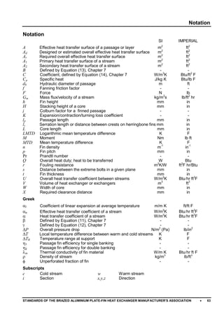
  • 1. B Defined by Equation (13), Chapter 7 - - C Coefficient, defined by Equation (14), Chapter 7 W/m3 K Btu/ft2 F Cp Specific heat J/kg K Btu/lb F dh Hydraulic diameter of passage m ft f Fanning friction factor - - F Force N lb Gm Mass flux/velocity of a stream kg/m2 s lb/ft2 hr h Fin height mm in H Stacking height of a core mm in j Colburn factor for a finned passage - - K Expansion/contraction/turning loss coefficient - - lp Passage length mm in L Core length mm in LMTD Logarithmic mean temperature difference K F M Moment Nm lb ft MTD Mean temperature difference K F p Fin pitch mm in Pr Prandtl number - - Q Overall heat duty; heat to be transferred W Btu r Fouling resistance m2 K/W ft2 F hr/Btu s Distance between the extreme bolts in a given plane mm in t Fin thickness mm in U Overall heat transfer coefficient between streams W/m2 K Btuhr ft2 F W Width of core mm in X Required clearance distance mm in Greek l Coefficient of linear expansion at average temperature m/m K ft/ft F o Effective heat transfer coefficient of a stream W/m2 K Btuhr ft2 F  Heat transfer coefficient of a stream W/m2 K Btuhr ft2 F  Defined by Equation (11), Chapter 7 - -  Defined by Equation (12), Chapter 7 - - P Overall pressure drop N/m2 (Pa) lb/in2 TR Temperature range at support K F 1 Passage fin efficiency for single banking - - 2 Passage fin efficiency for double banking - - m Thermal conductivity of fin material W/m K Btuhr ft F  Density of stream kg/m3 lb/ft3  Unperforated fraction of fin - - Notation Notation SI IMPERIAL A Effective heat transfer surface of a passage or layer m2 ft2 Ad Designed or estimated overall effective heat transfer surface m2 ft2 Ar Required overall effective heat transfer surface m2 ft2 A1 Primary heat transfer surface of a stream m2 ft2 A2 Secondary heat transfer surface of a stream m2 ft2 ls Serration length or distance between crests on herringbone fins mm in n Fin density m-1 in-1 V Volume of heat exchanger or exchangers m3 ft3 T Local temperature difference between warm and cold streams K F Subscripts c Cold stream w Warm stream i Section x,y,z Direction STANDARDS OF THE BRAZED ALUMINIUM PLATE-FIN HEAT EXCHANGER MANUFACTURER'S ASSOCIATION  63
  • 2.
  • 3. References References (1) Ward, J.A., "Effectiveness-NTU Relationships", Data Item 86018, Engineering Sciences Data Unit, London, 1986. (2) Kays, W.M. and London, A.L., "Compact Heat Exchangers", McGraw Hill, New York, Third Edition, 1984. (3) Taborek, J. and Spalding, D.B., "Heat Exchanger Design Handbook", Hemisphere Publishing Corporation, 1983. (4) Taylor, M.A., "Plate-Fin Heat Exchangers - Guide to Their Specification and Use", HTFS, 392.7 Harwell, Oxon, OX11 0RA, UK. 1987. STANDARDS OF THE BRAZED ALUMINIUM PLATE-FIN HEAT EXCHANGER MANUFACTURER'S ASSOCIATION  65
  • 4.
  • 5. Index Index Acceptable Fluids ...........................................2 AD-Merkblätter .............................................35 Aftercooler ......................................................2 Air Separation Unit(ASU)................................2 Air test ..........................................................36 Ammonia .................................................... 2, 3 Angle Bracket Support Arrangement ............ 26 Argon...............................................................3 AS 1210........................................................35 ASME VIll, Div. 1 ..........................................35 Asphyxiation .................................................32 Atmospheric Corrosion .................................62 Banking Multiple .....................................................46 Single........................................................46 Beams Support .....................................................23 Block (core) ....................................................4 Blocking of Layers ........................................22 Burst test method..........................................41 Butane .............................................................3 Cap sheet .......................................................4 Cap Sheets...................................................41 Carbon Dioxide........................................... 2, 3 Carbon Monoxide ....................................... 2, 3 Cascade Cooling...............................................3 Chillers ...........................................................2 Chlorine..........................................................2 Choice of Fin Geometry................................54 Cleaning ................................................. 20, 59 Solvent......................................................59 CODAP.........................................................35 Code Data Reports.......................................19 Codes for Construction .................................35 Coefficient of Thermal Expansion ................. 28 Colburn Factor..............................................50 Cold Boxes ...................................................32 Components of an Exchanger..........................................4 of Manifolded Exchangers...........................5 Condenser Overhead ....................................................2 Condensers ....................................................2 Connection Options Flanges.......................................................6 Stub Ends ...................................................6 Transition Joints..........................................6 CONTRACTUAL INFORMATION................. 17 Cool-down ....................................................31 Core (block)....................................................4 Core Volume Estimation .................................................52 Corrosion ......................................................60 Acidic Environments..................................61 Alkaline Environments...............................61 Atmospheric or Environmental...................62 Environments containing Mercury..............61 Water ........................................................60 Corrosion Allowances ...................................38 Damage........................................................33 Definition.......................................................35 Dephlegmators ...............................................2 Deplugging....................................................60 Description General .......................................................1 DESIGN HYDRAULIC .......................................45–55 THERMAL ...........................................45–55 Design Code.................................................17 Design Pressures..........................................35 Design Temperature .....................................37 Distributor Central ......................................................10 Diagonal....................................................10 Double Entry/Exit.......................................10 End..............................................................9 Intermediate ................................................9 Mitre..........................................................10 Side.............................................................9 Special ........................................................9 Split Flow...................................................10 Distributor fins.................................................4 Drawings.......................................................18 Approval and Change................................18 for Record .................................................18 Information ................................................18 Proprietary Rights......................................19 Drying ...........................................................20 Dummy Passages.........................................20 Dutch Pressure Vessel Code ........................35 Ethane .............................................................3 Ethylene...........................................................3 Exchanger block (core) .................................................1 cap sheets...................................................1 inlet ports.....................................................1 layers (passages) ........................................1 multi-stream ................................................1 outlet ports ..................................................1 parting sheets..............................................1 side bars......................................................1 size..............................................................1 FABRICATION........................................17–22 Failure Mechanism........................................57 STANDARDS OF THE BRAZED ALUMINIUM PLATE-FIN HEAT EXCHANGER MANUFACTURER'S ASSOCIATION  67
  • 6. Index Field Testing................................................. 29 Filters ........................................................... 31 Fin Corrugations............................................. 8 Fin Dimensions............................................... 9 Definition..................................................... 9 Fins Per Inch (FPI)...................................... 9 Percentage Perforation ............................... 9 Fin Geometry Choice of................................................... 54 Fin Types........................................................ 8 Fins .............................................................. 41 Herringbone................................................ 8 Perforated................................................... 8 Plain............................................................ 8 Serrated...................................................... 8 Wavy........................................................... 8 Fixing Bolts................................................... 27 Flange Protection ......................................... 20 Flanges ........................................................ 40 Flow Arrangements ...................................... 11 Co-Current Flow........................................ 11 Counterflow............................................... 11 Cross-Counterflow .................................... 11 Crossflow.................................................. 11 Flow Fluctuations.......................................... 57 Flow Velocities in Nozzles ............................ 39 Fluids Acceptable.................................................. 2 Fouling ......................................................... 58 Fouling Resistance....................................... 51 Freeze Spots................................................ 32 Freon............................................................... 3 General Description........................................ 1 GENERAL DESCRIPTION....................... 1–11 GOOD PRACTICE ................................. 57–62 Guarantees................................................... 19 Consequential Damage............................. 19 Corrosion .................................................. 19 Thermal and Mechanical........................... 19 Guide Frame Sliding....................................................... 24 Handling ....................................................... 23 Header Dome.......................................................... 7 Inclined Ends .............................................. 7 Mitred Ends................................................. 7 Standard ..................................................... 7 Header/Nozzle Configurations........................ 6 Headers.......................................... 4, 6, 38, 41 Heat Transfer Coefficient of a Stream........... 50 Heat transfer fins ............................................ 4 Heat Transfer Surface .................................. 47 Height............................................................. 4 Stacking...................................................... 1 Helium ............................................................. 3 Helium Leak Test.......................................... 34 Helium Recovery...............................................3 Helium test....................................................36 Hexane ............................................................3 HYDRAULIC DESIGN ............................45–55 Hydrogen .........................................................3 Hydrogen Sulphide .........................................2 Inactive Areas...............................................20 Injury.............................................................33 Inspection .....................................................17 Manufacturer’s ..........................................17 Purchaser’s ...............................................17 Third Party ................................................17 INSTALLATION ......................................23–34 Insulation ......................................................30 Japanese HPGS Law....................................35 Layer Arrangements .....................................40 Leak Detection..............................................32 Leak Rate .....................................................37 Leak Test......................................................36 Air .............................................................36 Helium.......................................................36 Length ............................................................4 Lifting............................................................23 Lifting Devices ..............................................21 Lifting lugs ....................................................21 Limits of Use Maximum working pressure.........................2 Maximum working temperature ...................2 Minimum design temperature......................2 Liquefaction ......................................................3 Liquefied Natural Gas ........................................3 Liquefied Natural Gas (LNG)...............................3 Liquefied Petroleum Gas (LPG)...........................3 Liquefiers........................................................2 Liquified Natural Gas (LNG)............................2 Logarithmic Mean Temperature Difference...50 Main Exchanger..............................................2 Maintenance .................................................32 MAINTENANCE......................................23–34 MATERIALS ...........................................43–44 Materials of Construction ........................35, 43 Mean Temperature Difference ......................47 MECHANICAL STANDARDS ................. 35–42 Mercury.....................................................3, 61 Metal Temperature Limitations......................37 Methane...........................................................3 Module Construction.......................................6 Mounting Bolts..............................................27 MTBE ..............................................................3 Multi-Component Refrigerants...........................3 Multiple Banking ...........................................46 Multi-Stream .................................................46 Nameplate ....................................................17 Data ..........................................................18 Manufacturer’s ..........................................17 Purchaser’s ...............................................18 68  STANDARDS OF THE BRAZED ALUMINIUM PLATE-FIN HEAT EXCHANGER MANUFACTURER'S ASSOCIATION
  • 7. Structure ...................................................17 Supplementary Information .......................18 Natural Gas Processing (NGP)...................2, 3 Nitrogen ...........................................................3 Nitrogen Dioxide .............................................2 Nitrogen Rejection Unit (NRU) ............................3 NOMENCLATURE.................................... 1–11 Nomenclature of the Components ..................4 Nonconformity Rectification ..........................21 Non-Destructive Testing ...............................29 Nozzle Inclined .......................................................7 Radial..........................................................7 Tangential ...................................................7 Nozzle loadings ............................................39 Nozzle Type....................................................6 Nozzles........................................... 4, 6, 39, 41 Flow Velocities in ......................................39 Loadings ...................................................39 Operation......................................................31 OPERATION .......................................... 23–34 Overall Heat Transfer ...................................47 Overhead Condenser .....................................2 Oxygen ............................................................3 Particulate Matter..........................................31 Parting sheet ..................................................4 Parting Sheets..............................................41 Pentane ...........................................................3 Petrochemical Production...................................3 Piping .............................................................6 Plant Upsets .................................................57 Plugging ................................................. 58, 59 from dust ..................................................... 3 from molecular sieve dust ...........................3 from particulates..........................................3 Pressure Loss...............................................52 Single-Phase.............................................53 Two-Phase................................................54 Pressure Relief Device .................................31 Pressure Relieving Devices..........................31 Pressure Test ......................................... 33, 36 Hydrostatic................................................36 Pneumatic.................................................36 Pressure Testing ..........................................29 Pressure Vessel ...........................................41 Pressurising..................................................20 Primary Heat Transfer Surface ..................... 45 Production Process.......................................40 Proof Pressure Testing .................................29 Propane ...........................................................3 Propylene.........................................................3 Pulsing..........................................................31 Raccolta .......................................................35 Rare Gases ......................................................3 Reboilers ........................................................2 Rectification Index Leak ..........................................................22 Nonconformity ...........................................21 Rectification of Leaks....................................22 Refrigeration Systems........................................3 Repair of Leaks.............................................34 Reversing Exchanger......................................2 Safety ...........................................................33 Scope of Supply............................................20 Secondary Heat Transfer Surface.................45 Services..........................................................2 Shear Plate Support Arrangement ................25 Shipment.......................................................19 Shop Operation.............................................17 Shut-down.....................................................32 Side bars...................................................4, 41 Single Banking..............................................46 Single-Phase Pressure Loss.........................53 Site leak Detection........................................33 Sliding Guide Frame .....................................24 Solvent Injection System...............................59 Spare parts ...................................................21 Special Features...........................................42 Specification Sheets ...............................47–49 Stacking Arrangement...................................55 Stacking height ...............................................1 Standard Sizes .............................................38 Cap Sheets ...............................................38 Fins ...........................................................38 Parting Sheets...........................................38 Side Bars...................................................38 STANDARDS MECHANICAL.....................................35–42 Start-up.........................................................31 Subcooler Reboiler .........................................2 Sulphur Dioxide...............................................2 Supply Scope of....................................................20 Support Arrangement Angle Bracket............................................26 Shear Plate ...............................................25 Support Beams .............................................23 Support Insulation.........................................24 Supports .......................................................21 Surface Area.................................................47 Surging .........................................................31 Swedish Pressure Vessel Code....................35 Temperature Design.......................................................37 Temperature Differences Permissible................................................37 Temperature Limitations ...............................37 Testing..........................................................36 Field ..........................................................29 Non-Destructive.........................................29 Pressure....................................................29 THERMAL DESIGN................................45–55 STANDARDS OF THE BRAZED ALUMINIUM PLATE-FIN HEAT EXCHANGER MANUFACTURER'S ASSOCIATION  69
  • 8. Thank you for trying Solid Converter PDF Professional. The trial version of this product only converts 10% of your document, with a 10 page maximum. For this conversion, Solid Converter PDF Professional converted 7 of 78 pages. Please purchase Solid Converter PDF Professional at http://www.solidpdf.com/buy.htm to remove this restriction.