This document describes a mounting arrangement for an axial flow fan. It discloses a fan mounting that includes a plurality of curved arms to mount the fan to a structure defining a circular passage. The mounting arrangement is designed to improve acoustic noise performance and minimize packaging while maintaining efficiency. The document provides details of the fan design, including its hub, blades, and electric motor connection. It also references other prior art fan mounting arrangements.
This document describes improvements to ventilators and provides details of GB785218(A). It contains the following key information:
1) GB785218(A) relates to a ventilator with one or more groups of parallel pivoted louvres that are connected for parallel movement. The louvres are arcuate in cross-section and rotate to open and close the ventilator.
2) Each louvre is mounted on a pivot rod and connected to a control linkwork so that all louvres in a group rotate through the same angle simultaneously. This provides smooth air flow and directs air flow when open.
3) The ventilator can be made weather
This document describes an aircraft with a variable wing area, specifically a jet aircraft. It has a fixed wing for normal high-speed flight and a retractable wing for takeoff and landing. The retractable wing rotates about an axis within the fuselage from a retracted position inside the fuselage to a working position. It has a thick airfoil and Fowler flaps to generate extra lift at low speeds during takeoff and landing. The fixed wing is optimized for high-speed cruise flight.
The document describes a piston-type slide valve for steam locomotives. The slide valve has two components on each end that are normally held together under steam pressure but can separate when the engine is idling. This allows ports on both ends of the cylinder to communicate through apertures in the inner component and equalize pressure in the cylinder ends when coasting. The separation is achieved using a spring located between the two components on each end of the slide valve.
[Writing Sample] USPTO Office Action Response by Bryan Johnsonimpekable
This document contains amendments to a patent application for a muffler pipe storage rack. It includes amendments to 15 paragraphs of the specification to clarify descriptions of the rack and its dimensions. It also includes amendments to 14 claims, clarifying language around dimensions of slots and clearances for accommodating muffler pipes of various sizes. One claim is withdrawn.
This document summarizes a patent for an electrical heating panel assembly. It describes a frame that holds a panel made of two bonded sheets of insulating material with an electrical heating resistance in between. The panel is set back from the frame edges to allow air circulation behind the panel and between panels when multiple units are installed together. The heating resistance takes a sinuous path between the panel sheets for even heat distribution.
This document is a patent application for a pistol with a firing mechanism that can be easily adapted to operate in different modes. It describes a basic pistol design that functions in a double-action only (DAO) mode. The firing mechanism can be modified slightly to enable single-action (SA) or double-action/single-action (DA/SA) modes of operation. The application contains detailed drawings and descriptions of the components of the firing mechanism and how they interact for DAO, SA, and DA/SA modes. The goal is to provide a modular pistol design that reduces production costs by enabling different operation modes using a common basic design and components.
This patent describes a telescoping antenna tower assembly comprising a plurality of hollow triangular tubular sections nested within each other. Pulley wheels mounted on the sections guide a cable that is used to raise and lower the tower. As the cable is wound onto a winch, the successive tubular sections are elevated one within the other to erect the tower. Reversing the winch causes the sections to retract back into their collapsed position in the reverse order. The design aims to create a lightweight yet structurally rigid telescoping tower that can be easily erected and collapsed by a single operator.
The patent describes a steamer device comprising a body containing a steam generation unit. The device has first and second side panels attached to the body that provide wrapping locations for storage of a power cord and steam supply hose. The wrapping locations are formed between the body and side panels and allow the cord and hose to be neatly wrapped and stored when not in use.
This document describes GB780057 (A), a patent from 1957 for improvements to torque-limiting couplings. The coupling uses rollable drive bodies like balls or rollers that are displaceable under spring pressure to transmit motion between two coupling members. One member is constructed as an inclined bearing that supports the other rotatably and axially carried member. The drive bodies engage in depressions in one of the coupling members to provide a positive connection.
This document summarizes a patent for a machine that applies rubber caps to containers. It describes a machine with fingers arranged in an annular form that can place a cap, and pistons that impart radial movement to the fingers. It also includes a rotary table to carry containers, a head carrying the fingers that can slide, and a piston to actuate the head. The machine applies caps by extending the fingers to stretch the cap over the container, then retracting the fingers to leave the cap in place.
1) Humans began dreaming of flight by observing birds thousands of years ago and made early attempts with kites, balloons, and airships. Modern aviation began in 1903 with the Wright brothers' successful powered airplane. 2) Modern commercial aircraft come in various shapes and sizes but primarily transport people and cargo worldwide. 3) This paper discusses the design of modern commercial aircraft and their key structural parts that enable more efficient and safe flight than earlier planes, including the fuselage, wings, empennage, power plant, and undercarriage.
This patent is for a worm-drive compressor with at least one first and one second main rotor on a main shaft that mesh with matching first and second sub-rotors on a layshaft. To provide an efficient compressor that is durable and inexpensive to produce, the bearings for the main and layshaft are placed radially near where the loads from the compressed gas pressures act to absorb those loads. This reduces wear on the shafts and bearings. The rotor geometries are also designed to cancel out opposing axial forces from the compressed gas to further reduce wear.
This document describes improvements to magnetic separators and radial flow compressors. It discusses magnetic separator filter elements with slots and walls extending perpendicular from the slots. It also discusses a method of manufacturing radial flow compressors with different characteristics by using interchangeable rotor and insertion sets, including open and closed rotor types.
This patent document describes improvements to power-operated typewriters that allow for automatic underscoring of typed text. Specifically, it provides a device with an auxiliary type bar and associated driving mechanism that is activated each time the main type bars are used. This allows any typed text to be automatically underscored without additional steps, improving efficiency. The device is activated by a lever that is linked to a bail mechanism connected to the main type bars, so that typing any character also triggers the auxiliary type bar to print an underscore.
This patent document describes improvements to a power-operated typewriter that allows for automatic underscoring. It includes an auxiliary type bar and associated drive mechanism. When any type bar is actuated, connecting means operates an auxiliary actuating lever to drive the auxiliary type bar and print an underscore in the same location. This allows words or paragraphs to be underscored without the typist having to go back and manually underscore each letter.
This document describes a patent for improvements to clamps for fixing dress guard stays on wheel axles of baby carriages. The clamp comprises two clamping arms that grip the axle between them. Each arm is pivotally mounted to a metal strip forming the stay. An abutment on the strip or arm holds the arms in a spaced position to insert the axle before tightening. The arms can then be pulled together on the axle by a clamping bolt. This allows the arms to be easily positioned around the axle without wasting time adjusting their position.
This patent document describes an electromagnetic motor with a reciprocating armature. It includes a fixed magnetic field member with an opening for an iron armature to move through. Current rectifying means create a pulsating magnetic flux to drive the armature in one direction. A spring or additional magnetic field member drives it in the opposite direction. Adjusting the spring tension can match the natural frequency of the armature to the pulsating flux frequency for increased stroke length. The motor can power air compressors or pumps.
This patent document describes an electromagnetic motor with a reciprocating armature. It includes a fixed magnetic field member with an opening for an iron armature to move through. Current rectifying means create a pulsating magnetic flux to drive the armature in one direction. A spring or additional magnetic field member drives it in the opposite direction. Adjusting the spring tension can match the natural frequency of the armature to the pulsating flux frequency for increased stroke length. The motor can power an air compressor with pistons connected to the armature.
The document describes improvements to velocity modulated discharge tubes. It includes an elongated evacuated envelope with an electron gun at one end and a collector electrode at the other end. Cavity resonator portions are disposed transversely between spaced metal tube sections to form gaps. Each resonator portion includes parallel disk-shaped metal end walls mounted on adjacent tube sections and extending outwardly, with a cylinder of insulating material sealed between the end walls.
This document is a patent for a self-loading semiautomatic pistol filed by Marion W. Yale on February 3, 1950. It includes detailed diagrams and descriptions of the pistol's components and operating mechanisms. The pistol has an enclosed action with no outside moving parts except an operating rod. It is designed to be simple in construction, easy to dismantle and clean, and capable of being quickly reassembled to provide a well-balanced weapon.
This document describes British patent GB784713 (A) from 1957 regarding improvements to fire alarms for combustible materials. It involves using continuous detector tubes made of fusible or thermally plastic material arranged in the combustible material. If a fire causes the temperature to rise, it will melt or soften the tube and reduce pressure, triggering an alarm. The tubes can have a sinuous shape and there can be multiple tubes to help locate an incipient fire. The document also provides details on the diagram and functioning of the alarm system using these fusible detector tubes.
1. A pistol includes a firing pin safety in the form of a resilient tongue attached to the breech part. The tongue has a hook that engages a shoulder on the striker when cocked. It also has a downward web that interacts with the trigger arm.
2. When the trigger is pulled, the trigger arm moves longitudinally and its finger pushes the resilient tongue's web outward, disengaging the hook from the striker shoulder.
3. The resilient tongue is integrally formed with an ejector spring that acts on an ejector claw, providing a simple, combined spring mechanism.
This document provides information on various engine systems and components. It includes:
- A list of engine ATA chapters and a table with engine specifications and performance parameters.
- Descriptions of the main engine sections - air intake, compressor, combustion chamber, turbine, exhaust system - outlining their functions, components, and designs.
- Details on other engine components and systems like mounts, cowls, thrust reverser, nozzle, bearing, seals, and the fuel control system.
- Explanations of compressor stall and surge, as well as bearing and seal types.
The document gives an overview of aircraft engine construction and operation through detailed descriptions and diagrams of key engine subsystems and components.
The document is a European patent application that describes an improved connection between the barrel and grip of a tilting barrel firearm. Specifically, it discloses a tilting barrel firearm with a frame and barrel connected by a pivot joint, wherein the pivot joint has a hollow pivot bore accommodating two cylindrical pivot pins inserted from each end. The pivot pins have enlarged heads on the rearward end and are secured axially in the pivot bore by resilient expanding rings. The application claims an insoluble connection between the barrel and grip achieved using this pivot joint configuration.
This document describes improvements relating to thrust bearings, specifically addressing the lubrication of large vertical shaft hydro-electric generators or pump motors. It involves a radial flow impeller pump comprising rotating blades mounted on a cylinder extending from the rotating thrust bearing member. The blades assist in circulating oil from an inner chamber to an outer chamber through radial passages in the rotating member. The outer ends of the passages can be fitted with removable nozzles to regulate the oil flow rate and pressure.
El documento describe cómo la gente de América Latina está forjando una nueva relación con su medio ambiente. Se compone de varios capítulos que presentan historias de individuos y comunidades que están trabajando para proteger y administrar de manera sostenible los recursos naturales, a menudo mediante el desarrollo de alternativas económicas como el ecoturismo. El autor argumenta que estas iniciativas están ayudando a las personas a depender menos de la destrucción de los ecosistemas y a ganar dinero de manera más respetuosa con
We are pleased to announce that Nice Ads presence is now all over Mumbai, Thane & Navi Mumbai area.
Nice Ads also known as Prime Spot Outdoors has recently acquired Tender of following Gantries in Western & Central belt:
Elphinstone Flyover, Traffic from Worli towards Dadar, One Way Road, Outside India Bulls Finance Centre, 170x10 (One of the Biggest Gantry in South Mumbai)
Elphinstone Flyover, Facing T Junction Lower Parel, Outside Lodha Park Project, 142x10
Elphinstone Flyover, Traffic from Parel towards Worli or Lower Parel, 90x10
Elphinstone Flyover, Traffic from Worli towards Dadar , One Way Road, 90x10
Borivali National Park, Fcg National Park, procdg Stn Goregaon & Dahisar, 100x10
Borivali National Park, Fcg Station, procdg Stn Goregaon & Dahisar, 100x10
Vikhroli Flyover, EEH, Traffic towards Bhandup or Ghatkopar, 132x10
Taloja, Taloja Kharghar Flyover, Traffic from Taloja towards Panvel or Vashi, 100x10
Thane Ganties 12 Qty at Teen Hath Naka, Hariniwas, Majhiwada Pokhran Road No. 02, Cadbury Junction, Khopat, Golden Dyes Subhash Nagar
Dadar FOB & East Hoardings - 14 Qty
Hoardings near Shil Phata 6 Qty
Kharghar Platform and Circulating Area Hoardings
Over 45 Hoardings in Panvel, Kalamboli, Taloja, Nawda Phata
Sole Rights of 8 Stations in Mumbai between Masjid to Panvel
To view pictures of our media refer attachment or click on following link;
http://www.slideshare.net/NiceOOH/prime-spot-outdoors-nice-ads-outdoor-advertising-media
For bookings and best deals contact Nikesh Gupta +91 9867452960 / +91 9892476001 or write to us on nikesh.ooh@gmail.com
We continue to remain at your disposal for any further queries or requirements you may have.
Thanking you,
Regards,
Nikesh Gupta
Proprietor: Nice Ads / PRIME SPOT OUTDOORS
+91 9867452960 / +91 9892476001
nikesh.ooh@gmail.com
26 Gantries all over Mumbai, Thane & Panvel
40 + hoardings at Panvel (Old Panvel, New Panvel, Kalamboli & ST Depot)
Sole Rights of: Dadar, Wadala, Masjid, Kharghar, Sandhurst, Cotton Green, Dockyard, Reay Road, Sewri, King Circle. Also, many media at Lower Parel, Vikhroli, Borivali, Elphinstone, Matunga, Bhandup, Dombivali, Sion Gandhi Market, Mankhurd, Taloja Nawda Phata, Sheel Phata, Mankhurd, Shil Panvel Road, Kalyan Goa Naka, Mumbra Panvel Road, Shil Thane Highway,Thane Nasik Highway Padgha Ulwe, Vasind, Ambivali, Asangaon etc..
Ep0888025 b1 Method and apparatus for providing partitioned telecommunication...zweisteine777
The document describes a method for partitioning a telecommunications network to allow multiple service providers to share network infrastructure while customizing services for their subscribers. A mobile switching center (MSC) is configured with a partition table associating subscriber identifiers like mobile identification numbers (MINs) with individual service providers. When a mobile station registers, the MSC looks up the associated service provider in the partition table and retrieves subscriber profile information from that service provider's home location register (HLR), allowing each provider to independently maintain subscriber data. This allows network sharing while enabling customized services, features, and voice mail systems for each service provider's subscribers.
10 cats that are ready to be taken anywhereHotheaded
The document shows 10 pictures of cats comfortably sitting in bags or backpacks. The cats appear relaxed and at home despite being carried around in bags and packs, suggesting they are ready to go anywhere in their mobile beds.
Ep0878712 Standardization of chromatographic systemszweisteine777
This document discusses standardizing chromatographic systems so that retention times are identical between different systems and the same system over time. It describes using a primary system to generate standard retention times using known samples and parameters. These are used to determine constants in a mathematical function relating retention times to system and operating parameters. A target system is then calibrated by determining parameters that generate retention times matching the primary system, allowing direct comparison of results between systems.
Ep1039758 b1 Apparatus for creating shared video scene contentzweisteine777
The document discusses opposition to a granted European patent. It states that within nine months of a European patent being published in the European Patent Bulletin, any person may file an opposition notice with the European Patent Office. It also notes that an opposition notice is not considered filed until the opposition fee has been paid, in accordance with the Implementing Regulations and Article 99(1) of the European Patent Convention.
Each year in the US, gun deaths total between 30,000 to 40,000 people, with homicides and suicides making up most of the toll. Homicide rates have remained constant while deaths from auto accidents have declined. Over 200 million guns are in circulation in the US despite only around 30% of adults owning guns, as gun owners now own multiple firearms on average. State gun laws vary considerably regarding licensing, permits, and waiting periods. The rise of school shootings and crimes with semi-automatic weapons are fueling the push for stricter nationwide gun control legislation.
This document discusses opposition to European patents. It notes that within nine months of a European patent being published, any person may file an opposition notice with the European Patent Office. The opposition notice is not considered filed until the opposition fee has been paid. It also restates part of the European Patent Convention that discusses this opposition process.
The document discusses plans for Smart City Maribor and the role of Nigrad d.d., a Slovenian utility company, in developing Maribor into a pilot smart city. Specifically, it outlines three key points:
1) By 2050, nearly 70% of the world's population will live in urban areas, exacerbating environmental and social challenges. Cities need to become "smart cities" to manage these challenges.
2) Nigrad provides various public utility services in Maribor and aims to develop Maribor into a pilot smart city through projects in areas like smart winter service, road audits, environmental integration, and infrastructure like street lighting and sewerage systems.
3
The Federal/HX Group operates an industrial park in Linfen, Shanxi Province, China covering the area of 680 football fields. The park has 11 casting production lines with an annual capacity of 230,000 tons and 25 machining lines with an annual capacity of 65 million pieces. It produces parts for various industries such as construction machinery, compressors, automobiles, pumps, valves, and pipes. In 2012, the group produced 160,000 tons of castings and achieved $210 million in sales.
Este documento evalúa la implementación del aprendizaje basado en proyectos (PBL) en la Escuela Politécnica Superior de Castelldefels (EPSC) entre 2001-2003. El PBL se utilizó para organizar el plan de estudios de segundo ciclo de ingeniería de telecomunicaciones en la EPSC, dividiendo cada semestre en bloques que incluían módulos presenciales y un proyecto grupal relacionado. El documento describe este plan de estudios basado en PBL y evalúa la experiencia desde la perspectiva de los estud
Este documento introduce el concepto de biodiversidad y discute su definición, orígenes e importancia. Explica que la biodiversidad se refiere a la variabilidad entre organismos vivos y los ecosistemas de los que forman parte. Luego describe los tres niveles de diversidad (genética, de especies y ecosistémica) y diferentes manifestaciones de la biodiversidad. Finalmente, resalta la preocupación actual por la conservación de la naturaleza dada la alta tasa de pérdida de especies.
This document describes a new class of substituted cyclopentyl compounds useful for therapeutic purposes. Specifically, it describes cyclopentyl acetic acid amides containing substituents that are obtainable by condensing cyclopentyl acetic acid or derivatives with ammonia, amines or ureas. The document provides an example for synthesizing cyclopentyl-bromo-acetamide in three steps: 1) brominating cyclopentyl acetic acid, 2) converting it to the acetylchloride derivative, and 3) reacting it with aqueous ammonia. These compounds have sedative properties and can be used as intermediates for producing other therapeutic agents or used directly as therapeutics.
This document describes two embodiments of a clothes dryer invention. The first embodiment uses turbine blades mounted on the rotating drum to be turned by incoming air from a vacuum cleaner, rotating the drum. The second embodiment uses a turbine connected to the drum via a reduction drive using friction pulleys to rotate the drum. Both embodiments aim to rotate a drum containing clothes using a flow of air from an external source like a vacuum cleaner to dry the clothes.
This patent document describes improvements to shaft bearings that provide lubrication regardless of motor position or rotation direction. The bearing features a journal sleeve and thrust members, with annular wicks that absorb lubricant and preload the thrust surfaces to prevent noise. Helical grooves in the shaft pump lubricant between the wicks to lubricate the journal and thrust surfaces, with means to return excess lubricant to ensure adequate supply in any conditions.
This document describes a patent for an apparatus to prevent the release of contaminants from the exhaust of an internal combustion engine. The apparatus recycles exhaust gas through the intake manifold during engine deceleration using a T-shaped fitting between the intake manifold and carburetor, another T-fitting between the exhaust manifold and tail pipe, a pipe connecting the fittings, and valves to shut off fuel and allow exhaust gas recycling during deceleration. The goal is to provide an effective and simple apparatus that can be easily installed and does not affect normal engine operation.
The document discloses a portable garage that attaches to a vehicle by securing to the outside of the vehicle's tires, rather than the vehicle's body or wheel hubs. The portable garage includes a canopy attached to masts. The masts are secured at their lower ends to mast bases. Each mast base includes hooks, arms, braces, and a bolt. When the bolt is turned, the arms and braces move the hooks to secure to the outside of the vehicle's tires. This allows the portable garage to shelter the vehicle without damaging the vehicle's surface or wheel hubs.
This patent describes a portable garage that attaches to a vehicle's tires rather than its body or wheel hubs. The garage includes a canopy attached to a mast. The mast connects to a base that clamps onto the outside of the tires. The base has a plate with a threaded center opening. Arms extend from the base and end in hooks that fit around the tires. Turning a bolt causes the arms to move in or out to adjust to different tire sizes. This allows the garage to shelter the vehicle without contacting and potentially damaging its surfaces.
This document provides a summary of a patent application for improvements to a suction cleaning nozzle. Specifically, it aims to overcome the difficulty of litter adhering to the inside of the suction nozzle and conduit by supplying pressurized water through ejection openings. The ejected water spreads as a film along the inside surfaces to sweep away any adhered litter and prevent clogging. The water ejection openings are located to ensure the water film sweeps all relevant inside surfaces under the influence of the blowing and suction air.
This document provides a description and specification for improvements to suction cleaning nozzles, specifically for cleaning streets. It details the technical issues previously encountered with street cleaning machines using suction nozzles and how the present invention addresses one challenge around litter adhering to the inside of the suction nozzle and conduit. Diagrams and details are provided to illustrate the nozzle arrangement, including the addition of water ejecting openings to help prevent clogging by spreading a water film inside the nozzle and conduit.
1) The document describes improvements in automatic rammer mechanisms for guns.
2) It aims to provide a fully automatic rammer that uses free-flight delivery of ammunition into the gun breech to minimize the time between rounds and protect the ramming mechanism from damage from premature breech closure.
3) Free-flight delivery also allows more accurate insertion of rounds into the breech under varying conditions like pitch and roll of the gun.
This document describes improvements to control means for electric current converters. It discusses providing control of discharge paths through respective control electrodes over a wide range, from rectifier to inverter operation. Each control electrode is connected to two inductive members (transformers or chokes) supplied with phase-displaced operating currents/voltages from AC busbars. There are means for imparting a commonly variable direct current premagnetization and means for imparting independently pre-settable direct current premagnetizations, allowing control of each electrode's feed to provide a control voltage during a portion of the converter's total control range.
This document describes improvements to gyroscope apparatus. It summarizes two different gyroscope designs that use air bearings to support a rotating gyroscope rotor. In the first design, the rotor is supported within a concentric casing on a spherical air bearing. The casing is driven by a tubular drive shaft connected to conventional bearings. In the second design, a wheel-shaped rotor is supported within a spherical casing on an air bearing. The casing is driven by electric motor integrated with the lower casing portion and supported by ball bearings. Both designs use pickoffs and electromagnetic means to apply torques to the rotor and counteract precession forces to keep the rotor axis aligned with the casing rotation axis.
This document describes two British patents from 1957:
1) GB784929(A) describes aircraft doors for a bomb bay that open by sliding up the outside of the aircraft rather than swinging downward to reduce drag.
2) GB784930(A) describes a movable platform in an aircraft bomb bay that can lower a bomb/missile below the bay opening while largely closing the opening to further reduce drag when bombing. The platform is operated by lever arms connected to jacks.
This patent application describes a tire sealant delivery system that can selectively dispense either tire sealant or compressed air into a tire. The system includes a container holding the sealant with a movable piston, a threaded shaft engaged with the piston to push it forward when rotated, and a tube connecting the container to a tire valve. It also includes an electric actuator to rotate the shaft and push out the sealant, an air compressor, and a valve that can selectively direct either the sealant or compressed air to the tire.
This document describes British patent GB785774 filed in 1957. It relates to an improved means of detachably attaching two parts together using a U-shaped strap with parallel slits that cooperate with pins, screws or the like on the other part. The strap can detachably attach objects like a car radio to a vehicle's instrument panel in a cheap and practical manner.
Inventors and entrepreneurs have vocations fueled by passion. Many would have done it for free or as a hobby if it hadn’t become a profession. Mark Rosenzweig is a natural creator, driven by his passion. This fuel has led Mark to develop his ideas into viable products and innovations that he has been patenting since 2003. From an innovative filter sensor and indicator for vacuum cleaners to a basket for deep fryer and methods of cooking food products to a compact cyclonic bagless vacuum cleaner. Sometimes independently and often as part of creative teams, Mark has patented just under one hundred innovative inventions between 2003 and 2017.
This document describes floor cleaning and polishing equipment. It has a shaft that is pivotally attached to a base so it can be adjusted to different angles. To achieve an adjustable handle position, the shaft has a retractable rod with an end that can lodge in perforations on an arcuate strip below the shaft end. This immobilizes the shaft at the desired angle. The strip can have two holes to position the shaft upright or at a preset angle, or more holes for additional angles. The strip can also be located under the base for a compact design.
This document describes a patent for improvements in friction couplings used in baling machines and other power driven machines. Specifically, it details a friction coupling that provides an audible alarm when slipping occurs. The coupling has two plates between which are fabric-lined slip discs. When slipping causes the slip discs to rotate, it actuates an audible alarm such as a bell. Alternatively, ratchet teeth on the slip disc can click against a spring to produce an audible warning of slipping. The invention provides a way to detect and warn of slipping in a friction coupling.
This document is a patent specification from 1957 describing improvements to screw presses. It details a screw press design that uses a hollow screw spindle with a suspension rod running longitudinally through it. The suspension rod engages with a thrust bearing assembly carrying the sliding head and is mounted at one end of the spindle. This overcomes issues with prior designs like notch effects and screw breakages, while allowing the screw to withstand greater pressures.
Similar to Ep0704626 b1 FAN MOUNTING ARRANGEMENT (20)
Safeguarding Against Financial Crime: AML Compliance Regulations DemystifiedPROF. PAUL ALLIEU KAMARA
To ensure the integrity of financial systems and combat illicit financial activities, understanding AML (Anti-Money Laundering) compliance regulations is crucial for financial institutions and businesses. AML compliance regulations are designed to prevent money laundering and the financing of terrorist activities by imposing specific requirements on financial institutions, including customer due diligence, monitoring, and reporting of suspicious activities (GitHub Docs).
Pedal to the Court Understanding Your Rights after a Cycling Collision.pdfSunsetWestLegalGroup
The immediate step is an intelligent choice; don’t procrastinate. In the aftermath of the crash, taking care of yourself and taking quick steps can help you protect yourself from significant injuries. Make sure that you have collected the essential data and information.
Corporate Governance : Scope and Legal Frameworkdevaki57
CORPORATE GOVERNANCE
MEANING
Corporate Governance refers to the way in which companies are governed and to what purpose. It identifies who has power and accountability, and who makes decisions. It is, in essence, a toolkit that enables management and the board to deal more effectively with the challenges of running a company.
Capital Punishment by Saif Javed (LLM)ppt.pptxOmGod1
This PowerPoint presentation, titled "Capital Punishment in India: Constitutionality and Rarest of Rare Principle," is a comprehensive exploration of the death penalty within the Indian criminal justice system. Authored by Saif Javed, an LL.M student specializing in Criminal Law and Criminology at Kazi Nazrul University, the presentation delves into the constitutional aspects and ethical debates surrounding capital punishment. It examines key legal provisions, significant case laws, and the specific categories of offenders excluded from the death penalty. The presentation also discusses recent recommendations by the Law Commission of India regarding the gradual abolishment of capital punishment, except for terrorism-related offenses. This detailed analysis aims to foster informed discussions on the future of the death penalty in India.
Sangyun Lee, 'Why Korea's Merger Control Occasionally Fails: A Public Choice ...Sangyun Lee
Presentation slides for a session held on June 4, 2024, at Kyoto University. This presentation is based on the presenter’s recent paper, coauthored with Hwang Lee, Professor, Korea University, with the same title, published in the Journal of Business Administration & Law, Volume 34, No. 2 (April 2024). The paper, written in Korean, is available at <https://shorturl.at/GCWcI>.
Business law for the students of undergraduate level. The presentation contains the summary of all the chapters under the syllabus of State University, Contract Act, Sale of Goods Act, Negotiable Instrument Act, Partnership Act, Limited Liability Act, Consumer Protection Act.
1. Printed by Jouve, 75001 PARIS (FR)
(19)EP0704626B2
TEPZZZ7Z46 6B T
(11) EP 0 704 626 B2
(12) NEW EUROPEAN PATENT SPECIFICATION
After opposition procedure
(45) Date of publication and mention
of the opposition decision:
12.02.2014 Bulletin 2014/07
(45) Mention of the grant of the patent:
14.05.2003 Bulletin 2003/20
(21) Application number: 95306851.7
(22) Date of filing: 28.09.1995
(51) Int Cl.:
F04D 29/60 (2006.01)
F04D 19/00 (2006.01)
F04D 29/32 (2006.01)
F04D 25/08 (2006.01)
(54) FAN MOUNTING ARRANGEMENT
ANORDNUNG ZUR MONTAGE EINES LÜFTERS
ARRANGEMENT DE MONTAGE D’UN VENTILATEUR
(84) Designated Contracting States:
DE ES FR GB IT
(30) Priority: 29.09.1994 US 314827
31.05.1995 US 456178
(43) Date of publication of application:
03.04.1996 Bulletin 1996/14
(60) Divisional application:
03075277.8 / 1 302 670
(73) Proprietor: VALEO THERMIQUE MOTEUR
78320 Le Mesnil Saint-Denis (FR)
(72) Inventor: Alizadeh, Ahmad
Indianapolis, Ind. 46250 (US)
(74) Representative: Rolland, Jean-Christophe et al
Valeo Systèmes Thermiques
8 Rue Louis Lormand
BP 517 - La Verrière
78321 Le Mesnil Saint-Denis Cedex (FR)
(56) References cited:
EP-A- 0 242 342 EP-A- 0 521 285
EP-A- 0 569 738 DE-A- 1 488 640
DE-A- 4 143 383 DE-A- 4 222 264
DE-U- 8 612 292 FR-A- 2 214 340
US-A- 3 385 516 US-A- 4 358 245
US-A- 4 805 868
• parts catalog "Passenger Car" 1990 & US 5 297
931 A 29 March 1994
• Service manual "Front wheel drive van/wagon" &
US 4 548 548 A 22 October 1985
• technical drawing "shroud, S-body"
• technical drawing "radiator fan, S-body"
• servicemanual "lebaron, spirit, acclaim, shadow,
sundance"
• technical drawing "shroud, A-body"
• technical drawing "fan, A-body"
• extract from "ATZ - automobiltechnische
Zeitschrift"
• further page of E1
2. EP 0 704 626 B2
2
5
10
15
20
25
30
35
40
45
50
55
Description
[0001] The present invention relates to a mounting ar-
rangement for an axial flow fan, for example a fan de-
signed to cool air flowing through a heat exchange sys-
tem in a vehicle.
[0002] When used in a vehicular application, a fan can
be arranged either to blow air through a heat exchange
system such as a radiator, if the heat exchange system
is on the high-pressure (downstream) side of the fan or
draw air through the heat exchange system if the heat
exchange system is on the low-pressure (upstream) side
of the fan.
[0003] The mounting of the fan is of particular concern
when used to move air in an enclosed engine compart-
ment. More particularly, the fan mounting is required to
prevent noise and other vibrations from being transmitted
between the rotating fan and the vehicle body work. An-
other requirement is that the mounting should, as far as
possible, prevent air from leaking-back around the pe-
riphery of the fan.
[0004] A first object of the present invention is to pro-
vide a fan mounting arrangement which is capable of
providing an improved acoustic noise performance.
[0005] A second object of the present invention is to
provide minimum fan packaging while maintaining, or in-
creasing, the fan system efficiency.
[0006] DE-A-4222264 discloses a mounting arrange-
ment for mounting an axial flow fan to a structure defining
a circular passage, the mounting arrangement having a
plurality of curved arms.
[0007] EP-A-521285 discloses a mounting arrange-
ment for mounting an axial flow fan to a structure defining
a circular passage, the mounting arrangement having a
plurality of arms skewed so as to form the same angle
with respect to a radius of the circular air passage.
[0008] The Supplement of Automobiltechnische
Zeitschrift, AZT 95 Jahrgang /Nr 9, September 1993 de-
scribes a mounting arrangement for mounting an axial
flow fan to a structure defining a circular passage, the
mounting arrangement having three arms, one of them
being skewed.
[0009] According to the present invention there is pro-
vided a mounting arrangement for mounting an axial flow
fan to a structure defining a circular passage according
to the arrangement as claimed in claim 1.
[0010] Preferably the axial flow fan is secured to an
electric drive motor for driving the fan, and the mounting
arrangement supports the drive motor.
[0011] Preferably at least one arm has, at its support
structure end, an attachment finger extending in use par-
allel to the plane of the fan for sliding cooperation with
an attachment socket of said structure.
[0012] Preferably the fan comprises plural blades and
a bowl-shaped hub member having a front wall portion
extending to a peripheral side wall portion and plural in-
ternal radially-extending vane member for circulating air
within said hub member wherein each fan member has
a first portion extending forwardly along the side wall por-
tion and a second portion extending along the front wall.
[0013] Preferably, the fan is secured to an electric mo-
tor for driving the fan, a portion of the motor being dis-
posed within the hub member whereby in use the motor
is cooled by circulation of air caused by the vane mem-
bers.
[0014] Preferably, the fan has plural blades each se-
cured at a tip region thereof to a blade support band hav-
ing a radially-extending bell mouth portion and the struc-
ture defining a circular passage comprises a ring extend-
ing axially towards the bell mouth portion of the fan to
define, with said bell mouth portion, a first annular region
extending axially of the fan.
[0015] For a better understanding of the present inven-
tion and to show how the same may be carried into effect,
reference will now be made by way of example to the
accompanying drawings.
[0016] It is to be noted that Figures 10 and 11 are not
according to the present invention but are included in the
present application to preserve clarity as the description
of the embodiment shown in Figure 12, which is accord-
ing to the present invention, refers to the arrangements
in Figures 10 and 11.
Figure 1 is a perspective view of a fan from the front;
Figure 2 is a plan view of the fan of Figure 1, seen
from the front;
Figure 3 is a cross-section taken through the hub of
the fan along line III-III in Figure 2;
Figure 4 is a plan view of a hub insert for the fan of
Figures 1-3;
Figure 5 is a cross-section of the hub insert of Figure
4, taken along the line V-V in Figure 4;
Figure 6 illustrates diagrammatically the sweep, di-
hedral and pitch respectively of a fan blade;
Figure 7 is a cross-section through the fan taken
along the line VII-VII in Figure 2.
Figures 8 and 9 show the projection of a blade onto
the plane orthogonal to the blade axis;
Figure 10 shows a partial plan view of a fan mounting
arrangement;
Figure 11 shows a cross-section through a fan, elec-
tric motor and ring support taken along line XI-XI in
Figure 10;
Figure 12 shows a modification of the arrangement
of Figure 10;
Figure 13 shows a modification of the hub of Figure
3 with an improved form of cooling vane.
[0017] Figures 1 and 2 show a fan 2 which has a cen-
trally located cylindrical hub 4 with a plurality (seven as
illustrated) of blades6 extendingradially outwardly there-
from to an outer band 8 having a generally cylindrical
form.
[0018] The hub 4 carries a central hub insert 10 which
definesanaperture12for acceptingashaft whichmounts
the fan for rotation around its central axis. The blade sup-
1 2
3. EP 0 704 626 B2
3
5
10
15
20
25
30
35
40
45
50
55
port band8enclosesthebladesand isgenerally centered
on the axis of rotation of the fan 2. Each blade 6 extends
from a root region 14 secured to the hub 4 to an outer
(or tip) region 16 secured to the inner surface of the blade
support band 8. The tip region 16 of the blades 6 are
joined to the band over the full width of the blades and
not at a single point or over a narrow connecting line.
This increases the strength of the structure.
[0019] The blade support band 8 of the fan adds struc-
tural strength to the fan by supporting the blades at their
tip and also serves to hold air on the working surface of
the blades. The band 8 is of uniform thickness and has
a first axially extending cylindrical portion 9 and an axially
extreme portion 9a which is curved radially outwardly to
provide a bell-mouth, as is best seen in Figure 7.
[0020] The curved portion 9a of the band 8 reduces
losses due to vortices in a gap between the fan and a
shroud member surrounding the fan. The band 8 further-
more provides a uniform flow passage of air flow passing
through the fan and decreases unwanted variations in
the dihedral angle u and the pitch angle (see Figure 6)
of the blade by virtue of the tip support.
[0021] The blades 6 have respective leading edges B
and trailing edges C and are shaped so that they are
secured to the band 8 with the leading edge B tangential
to the curved portion 9a of the band. This can be seen
in Figure 7.
[0022] In use in a vehicular application for engine cool-
ing, the fan can be positioned in front of or behind an
engine cooling heat exchanger system comprising for
example a radiator, condenser and oil cooler. The fan
may be arranged so that air is either blown through the
heat exchanger system if the heat exchanger is on the
high pressure (downstream) side of the fan, or drawn
through the heat exchanger system, if the exchanger is
on the low pressure (upstream) side of the fan. The fan
2 is preferably used in conjunction with a shroud that
extends between the radiator and the outer edge of the
fan. The shroud serves to prevent recirculation of air
around the outer edge of the fan from the high pressure
region at the downstream side of the fan to the low pres-
sure region at the opposite side of the fan adjacent the
radiator. One known shroud structure is funnel-like as
shown for example in US-A-4,358,245. A second shroud
arrangement is shown in Figures 10-12, and will be de-
scribed later herein.
[0023] Reference will first be made to the design of the
hub having regard to Figure 3. The hub has a plastics
moulded body member 18 which defines an outer cylin-
drical hub ring 20 and an inner cylindrical hub ring 22.
The inner and outer hub rings define between them an
annular space 21. The inner cylindrical hub ring 22 has
first and second axially spaced annular ledges 24 and
25 which are directed radially inwardly. The ledges are
provided for supporting a hub insert 10 as described in
more detail hereinafter.
[0024] Referring to Figures 4 and 5, the hub insert 10
can be made of a plastics or metal material and is a body
formed as a solid walled cylinder 26 having a plurality of
peripheral circumferentially spaced protrusions 28 which
form a castellated outer surface. The castellations may
all be in the same plane perpendicular to the insert axis,
or may be in different planes perpendicular to that axis.
The insert 10 defines an aperture 12 having a first cylin-
drical portion and an adjoining portion in the form of a D
shape, that is having an arcuate portion 30 and an op-
posing single flat portion 32. The flat portion 32 is for
keying to a shaft inserted into the aperture 12 whereby
rotation of the shaft with respect to the hub insert 10 is
prevented. The castellated outer surface of the hub insert
10 enables the hub insert to be connected to the plastics
moulded portion 18 of the hub in a single manufacturing
step. That is, a mould defining the plastics moulded body
portion 18 is provided in which the hub insert 10 is placed.
Plastics material is injected into the mould in a known
injection moulding process and enters between the pro-
trusions 28 of the hub insert. Thus, a secure mechanical
connection is provided between the hub insert 10 and
the plastics moulded portion 18. The hub insert 10 pro-
vides a close fit and thus reduces the play between a
shaft inserted into the aperture 12 and the insert 10. This
thus helps preserve the fan balance when rotating and
reduces drift of the fan from true axial rotation.
[0025] Use of a single flat portion 32 is advantageous
in that the hub insert 10, and hence the fan, is always
mounted in the same orientation with respect to the shaft.
Hence balancing measures may be taken, without the
possibility of the fan being refitted after removal in the
opposite orientation, as would be possible if two flat por-
tions were provided on both shaft and hub.
[0026] However, where such considerations are not
significant, two or more flats could be provided, the same
number being present in the shaft.
[0027] Referring again to Figure 3, the annular space
21 between the inner and outer hub rings may accom-
modate the front face of an electrical motor provided to
drive the shaft. The motor is then protected by the mould-
ed portion from the intrusion of moisture and dust.
[0028] The outer surface of the fan hub 4 approximates
to a bowl shape which is more rounded than the straight
cylindrical hubs of the prior art. More particularly, the hub
outer surface has a central shallow depressed region 15
flanked by a substantially straight angled annular region
50. The annular region extends to a substantially planar
annular region 52 which further extends into an outer
cylindrical surface 55 of the hub via a radiussed portion
54. The elimination of a sharp angle at the front part of
the hub reduces vortices forming at the hub surface. The
formation of vortices, knownas "vortex shedding" causes
undesirable turbulence in the flow in the region of the
hub, and gives rise to increased noise levels.
[0029] The minimum extent of the hub in the axial di-
rection is at least equal to the axial blade extent at the
root of the blade 6. The axial extent of the hub 4 and of
the blade support band 8 respectively may vary up to
50% of the axial extent of the band 8.
3 4
4. EP 0 704 626 B2
4
5
10
15
20
25
30
35
40
45
50
55
[0030] The inner surface of the hub moulded portion
18 is provided with a plurality of radially extending ribs,
one of which can be seen in Figure 3 designated by ref-
erence numeral 19. The ribs 19 of which two are provided
for each blade, are curved with the moulded plastics sec-
tion 18 and serve to guide flow recirculating in the rear
part of the hub in an effective manner to cool an electric
motor by dissipating heat generated thereby. The ribs 19
extend radially inwardly towards the inner cylindrical ring
22 and thus also provide structural support for the hub
body and hub insert.
[0031] Referring again to Figures 1 and 2, the blades
of the fan will now be described. As shown in Figure 1,
each blade 6 is rearwardly skewed in that the medial line
of the blade (which is the line obtained by joining the
pointsthat arecircumferentiallyequidistant from thelead-
ing edge B and the trailing edge C of the blade) is curved
in a direction (root to tip) opposite to the direction D of
rotation of the fan 2. The leading and trailing edges B,C
are curved in the same direction. The skew is referred to
herein as the tangential sweep of the blade and is indi-
cated diagrammatically by the angles λ1, λ2 and λ3 in
Figure 8. Furthermore, each blade is secured to the hub
so that the blade lies at a dihedral angle which is illus-
trated diagrammatically by angle m in Figure 6. The di-
hedral angle m is the angle between a tangent between
a tangent P-T to the blade surface and a plane P-Q per-
pendicular to the axis of rotation. Furthermore, the blade
is pitched so that the leading and trailing edges B and C
are not in the same plane. The pitch angle γ alternatively
known as the chord angle is also shown in Figure 6.
[0032] Figure 7 shows in section the blade 6 and the
connection at the root to the hub 4 and at the tip to the
band 8. Figure 7 also shows a variation in the dihedral
angle m such that the dihedral angle decreases with re-
spect to the radius of the fan along the span of the blade
over the first 50% of the innermost radius and then stays
constant for the remaining 50%. As an alternative to the
dihedral angle remaining constant over the remaining
50% of the blade span, it could increase slightly over this
distance.
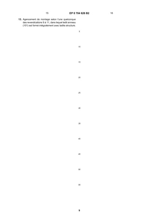
[0033] Reference will now be made to Figure 8 to de-
scribe the tangential sweep λ of the blade 6. In Figure 8,
the fan origin is indicated as O. The leading edge B of
the blade contains a portion BI at which the tangent D to
the curve passes through the origin. Similarly, the medial
line of the blade 6, shown as curve A, has a point AI, at
which the tangent x to the line passes through the origin,
and the curve C defining the trailing edge has a similar
portion CI extending tangentially to the radial line E.
[0034] Figure 9 illustrates the relationship between the
projection of the chord length at the root 14 of the blade
and that at the tip 16. Ri is the radius of the hub measured
from the fan origin O and θR is the angle subtended by
the root points CR, BR of the trailing and leading edges.
The root chord length projection SR is given by ST=RiθR
where θR is in radians.
[0035] Points CT and BT are the trailing and leading
edge tip points. Radii intersecting these tip points sub-
tend an angle θt. Hence the tip chord length projection is
ST=Rfθt where Rf is the outer fan radius. In the illustrated
embodiment, θR is greater than θt. Advantageously, the
chord length itself gradually increases from the root of
the blade over the first 50% of the span of the blade. The
chord length may then decrease over the whole remain-
ing span, or decrease up to about 70% of the span, after
which it remains constant.
[0036] Referring again to Figure 1, it will be seen that
the blade is pitched so that the leading and trailing edges
B and C are not in the same plane. The angle that the
blade chord makes with the horizontal axis is termed the
chord angle. The chord angle decreases with respect to
the radius of the fan, preferably along the entire blade
length. The projected blade width gradually decreases
from the root of the blade along the span of the blade,
i.e. with increase of blade radius.
[0037] The blade described herein provides a down-
stream variable axial flow velocity which increases con-
tinuously from the hub 4 to the outermost region of the
blade, with the maximum axial velocities occurring over
the span of the blade at the outermost 25-35% of the
blade. This variation enables the performance efficiency
of the fan to be optimised whilst reducing the noise level.
[0038] Referring to Figures 10 and 11, a mounting ar-
rangement for a fan will now be described: -
[0039] Referring first to Figure 10, the mounting ar-
rangment generally consists of an outer annular ring 101
for coupling to the bodywork of a vehicle in which the fan
is to be mounted, for example for coupling adjacent to a
front face member, eg a so-called "plastic", of such a
vehicle, and an inner generally annular ring 102 for sup-
porting an electric motor (110 - see Figure 11) used to
drive the fan. The inner ring is secured to the outer ring
101 by three arms 103, 104, 105, which as shown in
Figure 10 extend generally radially. At the junction of
each arm with the inner ring 102 there is provided a re-
spective hole 106. Each arm is prolonged beyond the
outer periphery of the outer ring 102 to provide a respec-
tive bayonet fastening 107, 108, 109. The bayonet fas-
tenings permit the fan, attached to the mounting arrang-
ment to be axially offered to the counterpart opening of
the vehicle bodywork and then circumferentially rotated
into counterpart bayonet housings on the bodywork.
[0040] Referring now to Figure 11, the fan 4 is shown
secured to the electric drive motor 110, which in turn is
mounted into the inner ring 102 of the mounting arrange-
ment by a bracket 111. The bracket 111 is secured to
the mountingarrangement via asuitablescrew 112pass-
ing through a resilient mounting 130 described later here-
in, contained by hole 106. Wiring (not shown) for the mo-
tor is secured to and supported by one of the arms, so
as not to impede the flow of air. The outer ring 101 ex-
tends beside the cylindrical portion 9 of the blade support
band 8 of the blades to define a narrow annular passage-
way therebetween which extends radially from the band
8. A front face portion 115 of the ring 108 is disposed
5 6
5. EP 0 704 626 B2
5
5
10
15
20
25
30
35
40
45
50
55
immediately behind and adjacent the curved portion 9a
of the blade support band 8. The curved portion 9a of the
band extends radially beyond the innermost radial extent
of ring 101.
[0041] A member 113 consists of a generally annular
ring secured to or integral with the vehicle body 114 and
disposed forwardly of the fan. The ring member 113 has
a lip which extends radially of the fan and back towards
the curved portion 9a of the band 8. Member 113 and
curved portion 9a define another narrow annular pas-
sageway. The vehicle body 114 defines a circular pas-
sageway for receiving the fan, and this surrounds the
circumference of the bell mouth portion 9a to define a
further annular passageway. The assembly of the ring
101, the body 114 and the member 113, together with
the blade support band 8 provides a series of narrow
passages between the front and rear of the fan and
around the edge thereof. These passages form a laby-
rinth, and cooperate to impede blow-past of air. This im-
proves efficiency and reduces noise.
[0042] Continuing to refer to Figure 11, the bolt 112
securing bracket 111 with respect to the inner ring 102
is coupled tothering 102by a two-part resilient mounting,
which consists of a first sleeve 130 having a circumfer-
ential slot extending transversallyof theaxis of the sleeve
130 so that the sleeve is retained grommet-fashion on
ring 102. The sleeve has a radially-inner axial hole which
receives and houses a second sleeve 131, which second
sleeve has a radially-inner axial hole for the bolt 112.
[0043] As mentioned above, with reference to Figure
10 the inner ring is supported with respect to the outer
ring via three arms 103, 104 and 105. Three arms are
used to prevent acoustic coincidence between the
numberof bladesof thefanaswell asprovidingthelowest
impedance to air flow. Lack of acoustic coincidence pre-
vents resonances from forming which would increase
noise, lead to vibration or reduce the efficiency of the
device. The arrangement is both lightweight and rigid.
[0044] Also shown in Figure 11 is the manner of con-
nection of the fan to the motor 110. As shown the motor
has an axially projecting shaft 132 for mounting thereon
of the fan. The shaft has a flattened axial portion for co-
operation with the flat portion 32 of the hub insert and
also has a circular protruding portion embraced by the
circular aperture portion of the hub insert 10. An axially
distal portion of the shaft is threaded to accept a nut 133.
[0045] To mount the fan upon the motor shaft 132, the
motor and the fan are offered together and the fan is
rotated until the flat 32 coincides with the flat portion of
the motor shaft 132. The shaft may then be urged into
the fan, whereby the threaded distal portion projects from
the hub insert 10. The cylindrical part of the shaft is
housed by the circular aperture portion of the hub insert
10, serving to centre the fan. The flat on the shaft coop-
erates with the flat on the insert 10 to rotatably couple
the two together. The nut 133 is then applied to the end
of the shaft and tightened. For compactness the axial
extent of the nut is no greater than the axial extent of the
central shallow depressed region 15 of the hub outer sur-
face. When fully tightened the nut 133 engages with the
axially outer surface of the hub insert 10, rather than en-
gaging with the hub itself.
[0046] Where the fan is to be rotated clockwise, the
thread on the motor shaft and the nut are each left hand-
ed; where the fan is for anticlockwise rotation, right hand-
ed threads are used.
[0047] Referring now to Figure 12 a modification in ac-
cordance with the present invention, of the mounting ar-
rangement of Figure 10 is shown. Similarly to the ar-
rangement shown in Figure 10, the mounting arrange-
ment has an outer ring 101 and an inner ring 102. How-
ever in this case the inner and outer rings are connected
by arms 141, 142 and 143. To further reduce acoustic
co-incidence, the arm 141 forms an acute angle with re-
spect to a radius of the outer ring 101, the arm 142 forms
a less acute angle with a radius of the outer ring 101 and
the third arm 143 is parallel to such a radius.
[0048] Referring now the Figure 13, a hub 400, simi-
larly to hub 4 previously described with respect to Figure
3, carries a central hub insert 10 which defines an aper-
ture 12. The hub member 400 consists of a plastics
moulded body member 180 which has a substantially
planar front wall portion 181 of generally annular form.
The front wall portion 181 extends via a radiussed portion
182 into a peripheral side wall portion 183 which is cir-
cular-cylindrical. Thus the hub body member 180 is gen-
erally bowl-shaped. The peripheral side wall portion 183
supports the root portion of the plural blades of the fan.
[0049] The inner surface of the hub member 180 is
provided with plural radially-extending ribs, similarly to
ribs 19 shown in Figure 3. These ribs are not shown in
Figure 13, but are provided at the rate of one rib per
blade, for example one corresponding to the leading
edge of each blade. The inner surface of the hub member
180 isalso provided withplural internalradially-extending
vane members 190. The vane members 190 which are
provided one per blade are of considerably greater area
than the ribs 19, described herein with respect to Figure
3. The vane members 190 have a first portion 191 which
extends axially from the rearmost extremity of the periph-
eral sidewall portion along the peripheral wall portion to
a second portion 192 which extends radially outwardly
along the inside of the front wall portion 181.
[0050] The first portion 191 has a straight radially-inner
edge 193 which makes an angle J to a plane F-F’ which
is perpendicular to the fan axis. The second portion also
has a straight radially inner edge 194 which makes an
angle G with another plane H-H’ which is parallel to the
plane F-F’. It has been found that increasing the surface
area of the vane members 190 causes an increase of air
flow within the hub, due to action as a turbine. In the
described embodiment the angle J is 60 degrees and the
angle G is 8 degrees.
[0051] As previously herein before described an elec-
tric motor used for driving the fan may be partly accom-
modated within the confines of the hub. Larger vane
7 8
6. EP 0 704 626 B2
6
5
10
15
20
25
30
35
40
45
50
55
members increase the air flow through the motor, thus
enhancing the cooling of the motor. However the partic-
ular shape of the vane members will be determined by
the shape of the motor, since the hub must clear the
motor to allow rotation.
[0052] Accordingly the vane members may have one
or more straight edges, as shown in Figure 13, or may
be partly or wholly curved, either concave or convex ac-
cording to the constraints of the motor, the desired cool-
ing and the constraints imposed by the moulding tech-
nique. Equally the vane members may be aligned with
fan radius, or may be skewed with respect thereto. If
skewed, the vane members may be curved or straight,
and the direction of skew is the same as the direction of
rotation - for example, if the fan rotates clockwise, the tip
of each vane is clockwise with respect to the vane root.
[0053] Secondly the number of vane members can be
increased so as to further enhance the air flow. However
a problem may occur if a large number of large-area vane
members are provided, since the weight of the fan overall
is thereby increased. This adds to the inertia of the fan
and thus requires a larger motor to drive the fan.
[0054] It will also be appreciated that the absolute
number of vane members 190 and ribs- 19 per fan may
be varied, for example providing more than one vane
member per fan blade, or only one vane member for eve-
ry alternate blade.
Claims
1. A mounting arrangement for mounting an axial flow
fan (2) to a structure defining a circular passage, the
mounting arrangement consisting of an outer ring
(101) and an inner ring (102) and three arms (141,
142,143) extendable from a structure and connect-
ing the outer ring (101) and the inner ring (102), on
which arms (141,142,143) a fan (2) is supportable,
wherein each arm (141,142,143) is straight thereby
defining a respective longitudinal axis, character-
ised in that one arm (141) forms an acute angle with
respect to a radius of the outer ring (101), one arm
(142) forms a less acute angle with a radius of the
outer ring (101) and one arm (143) is parallel to such
a radius.
2. A mounting arrangement as claimed in claim 1
wherein the fan (2) is secured to an electric drive
motor (110) for driving the fan (2) and the mounting
arrangement supports the drive motor (110).
3. A mounting arrangement as claimed in claim 1
wherein at least one arm (141, 142,143) has, at its
support structure end, an attachment finger
(107,108, 109) extending in use parallel to the plane
of the fan (2) for sliding cooperation with an attach-
ment socket of said structure.
4. A mounting arrangement as claimed in claim 1
wherein the fan (2) comprises plural blades (6) and
a blow-shaped hub member (400) having a front
wall portion (181) extending to a peripheral side wall
portion (183) and plural internal radially-extending
vane members (190) or circulating air within said hub
member (400) wherein each vane member (190) has
a first portion (191) extending forwardly along the
side wall portion and a second portion (192) extend-
ing along the front wall (181).
5. A mounting arrangement as claimed in claim 4
wherein the first portion (191) of each vane (190)
extends substantially from the axially rearmost ex-
tremity of the side wall portion (183) forwardly to-
wards the front wall portion (181).
6. A mounting arrangement as claimed in claim 5
wherein the first portion (191) of each vane member
(190) has a straight inner edge describing a first an-
gle (J) to a plane perpendicular to the fan axis and
the second portion (192) has a straight inner edge
describing a second angle (G) to said plane.
7. A mounting arrangement as claimed in claim 4
wherein the fan (2) is secured to an electric motor
(110) for driving the fan (2), a portion of the motor
(110) being disposed within the hub member (400)
whereby in use the motor (110) is cooled by circula-
tion of air caused by the vane members (190).
8. A mounting arrangement as claimed 7 wherein each
vane member (190) is curved with respect to a re-
spective hub radius, the curvature being such that
the tip of each vane member (190) is offset from a
radius through the root of the vane (190), the offset
being in said first direction.
9. A mounting arrangement as claimed in Claim 1,
wherein the fan (2) has plural blades (6) each se-
cured at a tip region (16) thereof to a blade support
band (8) having a radially-extending bell mouth por-
tion (9a) and the structure defining a circular pas-
sage comprises a ring (101) extending axially to-
wards the bell mouth portion (9a) of the fan (2) char-
acterised in that said ring defines with said bell
mouth portion (9a), a first annular region extending
axially of the fan (2).
10. A mounting arrangement as claimed in claim 9
wherein the bell mouth portion (9a) has a circumfer-
ence defining with said circular passage, a second
annular region extending radially of the fan (2).
11. A mounting arrangement as claimed in claim 10
wherein the blade support band (8) has a cylindrical
portion (9) extending axially of the fan (2), and the
circular passage defines with said cylindrical portion
9 10
7. EP 0 704 626 B2
7
5
10
15
20
25
30
35
40
45
50
55
(9) a third annular region extending radially of the
fan (2).
12. A mounting arrangement as claimed in any one of
claims 9 to 11 wherein said ring (101) is a ring mem-
ber secured to said structure.
13. A mounting arrangement as claimed in any one of
claims 9 to 11 wherein said ring (101) is integrally
formed with said structure.
Patentansprüche
1. Montageanordnung zur Montage eines Axialströ-
mungslüfters (2) an einer einen kreisförmigen
Durchgang definierenden Konstruktion, wobei die
Montageanordnung aus einem äußeren Ring (101)
und einem inneren Ring (102) und drei Armen (141,
142, 143) besteht, die sich von einer Konstruktion
aus erstrecken können und den äußeren Ring (101)
und den inneren Ring (102) verbinden, wobei von
diesen Armen (141, 142, 143) ein Lüfter (2) abge-
stützt werden kann und jeder Arm (141, 142, 143)
gerade ausgeführt ist, so dass er eine jeweilige
Längsachse definiert, dadurch gekennzeichnet,
dass ein Arm (141) einen spitzen Winkel bezüglich
eines Radius des äußeren Rings (101) bildet, ein
Arm (142) einen weniger spitzen Winkel mit einem
Radius des äußeren Rings (101) bildet, und ein Arm
(143) parallel zu einem solchen Radius verläuft.
2. Montageanordnung nach Anspruch 1, bei der der
Lüfter (2) an einem elektrischen Antriebsmotor (110)
zum AntriebdesLüfters(2)gesichertist unddieMon-
tageanordnung den Antriebsmotor (110) abstützt.
3. Montageanordnung nach Anspruch 1, bei der min-
destens ein Arm (141, 142, 143) an seinem Stütz-
konstruktionsende einen Befestigungsfinger (107,
108, 109) besitzt, der sich im Gebrauch parallel zur
Ebene des Lüfters (2) erstreckt, um mit einer Befe-
stigungsbuchse der Konstruktion gleitend zusam-
menzuwirken.
4. Montageanordnung nach Anspruch 1, bei der der
Lüfter (2) mehrereFlügel (6) undeinmuldenförmiges
Nabenelement (400) mit einem Vorderwandab-
schnitt (181), der sich zu einem Umfangsseiten-
wandabschnitt (183) hin erstreckt, sowie mehrere in-
nenliegende, sich radial erstreckende Schaufelele-
mente (190) zur Luftumwälzung innerhalb des Na-
benelements (400) umfasst, wobei jedes Schaufel-
element (190) einen ersten Abschnitt (191), der sich
nach vorne entlang dem Seitenwandabschnitt er-
streckt, und einen zweiten Abschnitt (192), der sich
entlang der Vorderwand (181) erstreckt, besitzt.
5. Montageanordnung nach Anspruch 4, bei der sich
der erste Abschnitt (191) jeder Schaufel (190) im we-
sentlichen vom axial hintersten Ende des Seiten-
wandabschnitts (183) aus nach vorne zum Vorder-
wandabschnitt (181) hin erstreckt.
6. Montageanordnung nach Anspruch 5, bei der der
erste Abschnitt (191) jedes Schaufelelements (190)
eine gerade Innenkante, die einen ersten Winkel (J)
zu einer senkrecht zur Lüfterachse verlaufenden
Ebene beschreibt, und der zweite Abschnitt (192)
eine gerade Innenkante, die einen zweiten Winkel
(G) zur Ebene beschreibt, besitzt.
7. Montageanordnung nach Anspruch 4, bei der der
Lüfter (2) an einem Elektromotor (110) zum Antrieb
des Lüfters (2) gesichert ist, wobei sich ein Abschnitt
des Motors (110) innerhalb des Nabenelements
(400) befindet, so dass der Motor (110) im Gebrauch
durch von den Schaufelelementen (190) bewirkte
Luftumwälzung gekühlt wird.
8. Montageanordnung nach Anspruch 7, bei der jedes
Schaufelelement (190) bezüglich eines jeweiligen
Nabenradius gebogen ausgeführt ist, wobei die Bie-
gungsobeschaffen ist, dassdie SpitzejedesSchau-
felelements (190) gegenüber einem durch die Wur-
zel der Schaufel (190) verlaufenden Radius versetzt
ist, wobei die versetzte Ausrichtung in der ersten
Richtung erfolgt.
9. Montageanordnung nach Anspruch 1, bei der der
Lüfter (2) mehrere Flügel (6) besitzt, wobei jeder an
einem Spitzenbereich (16) davon an einem Flügel-
stützband (8) mit einem sich radial erstreckenden
schalltrichterförmigen Abschnitt (9a) gesichert ist
unddieeinenkreisförmigenDurchgangdefinierende
Konstruktioneinen Ring (101) umfasst, der sich axial
zum schalltrichterförmigen Abschnitt (9a) des Lüf-
ters (2) hin erstreckt, dadurch gekennzeichnet,
dass der Ring mit dem schalltrichterförmigen Ab-
schnitt (9a) einen ersten ringförmigen Bereich defi-
niert, der sich axial zum Lüfter (2) erstreckt.
10. Montageanordnung nach Anspruch 9, bei der der
schalltrichterförmige Abschnitt (9a) einen Umfang
aufweist, der mit dem kreisförmigen Durchgang ei-
nen zweiten ringförmigen Bereich definiert, der sich
radial zum Lüfter (2) erstreckt.
11. Montageanordnung nach Anspruch 10, bei der das
Flügelstützband(8) einenzylindrischenAbschnitt (9)
aufweist, der sich axial zum Lüfter (2) erstreckt, und
wobei der kreisförmige Durchgang mit dem zylindri-
schen Abschnitt (9) einen dritten ringförmigen Be-
reich definiert, der sich radial zum Lüfter (2) er-
streckt.
11 12
8. EP 0 704 626 B2
8
5
10
15
20
25
30
35
40
45
50
55
12. Montageanordnungnacheinem der Ansprüche 9 bis
11, bei der der Ring (101) ein an der Konstruktion
gesichertes Ringelement ist.
13. Montageanordnungnacheinem der Ansprüche 9 bis
11, bei der der Ring (101) integral mit der Konstruk-
tion ausgeführt ist.
Revendications
1. Agencement de montage pour le montage d’un ven-
tilateur à flux axial (2) sur une structure définissant
un passage circulaire, l’agencement de montage
étant constitué d’un anneau extérieur (101) et d’un
anneau intérieur (102) et de trois bras (141, 142,
143) étant aptes à s’étendre à partir d’une structure
et reliant l’anneau extérieur (101) et l’anneau inté-
rieur (102), lesquels bras (141, 142, 143) étant aptes
à supporter un ventilateur (2), dans lequel chaque
bras (141, 142, 143) est rectiligne définissant de la
sorte un axe longitudinal respectif, caractérisé en
ce qu’un bras (141) forme un angle aigu par rapport
à un rayon de l’anneau extérieur (101) un bras (142)
formeunanglemoinsaiguavecunrayondel’anneau
extérieur (101) et un bras (143) est parallèle à un tel
rayon.
2. Agencement de montage selon la revendication 1,
dans lequel le ventilateur (2) est fixé à un moteur
électrique d’entraînement (110) pour entraîner le
ventilateur (2) et l’agencement de montage supporte
le moteur d’entraînement (110).
3. Agencement de montage selon la revendication 1,
dans lequel au moins un bras (141, 142, 143) a, à
son extrémité de structure de support, un doigt de
fixation (107, 108, 109) s’étendant en fonctionne-
ment parallèlement au plan du ventilateur (2) pour
une coopération coulissante avec un manchon de
fixation de ladite structure.
4. Agencement de montage selon la revendication 1,
dans lequel le ventilateur (2) comprend plusieurs pa-
les (6) et un élément de moyeu en forme de bol (400)
ayant une partie de paroi avant (181) s’étendant jus-
qu’à une partie de paroi latérale périphérique (183)
et plusieurs éléments d’ailettes internes (190)
s’étendant dans le sens radial pour produire une cir-
culation d’air dans ledit élément de moyeu (400),
dans lequel chaque élément d’ailette (190) a une
première partie (191) s’étendant vers l’avant le long
de la partie de paroi latérale et une deuxième partie
(192) s’étendant le long de la paroi avant (181).
5. Agencement de montage selon la revendication 4,
dans lequel la première partie (191) de chaque ailet-
te (190) s’étend substantiellement à partir de l’extré-
mité la plus en arrière dans le sens axial de la partie
de paroi latérale(183) en avant vers la partiede paroi
avant (181).
6. Agencement de montage selon la revendication 5,
dans lequel la première partie (191) de chaque élé-
ment d’ailette (190) a un bord intérieur rectiligne dé-
crivant un premier angle (J) par rapport à un plan
perpendiculaire à l’axe du ventilateur et la deuxième
partie (192) a un bord intérieur rectiligne décrivant
un deuxième angle (G) par rapport audit plan.
7. Agencement de montage selon la revendication 4,
dans lequel le ventilateur (2) est fixé à un moteur
électrique (110) destiné à entraîner le ventilateur (2),
une partie du moteur (110) étant disposée dans l’élé-
ment de moyeu (400) de telle sorte qu’en fonction-
nement le moteur (110) est refroidi par la circulation
d’air produite par les éléments d’ailettes (190).
8. Agencement de montage selon la revendication 7,
dans lequel chaque élément d’ailette (190) est incur-
vé par rapport à unrayondemoyeurespectif, la cour-
bure étant telle que la pointe de chaque élément
d’ailette (190) est décalée par rapport à un rayon au
niveau du pied de l’ailette (190), le décalage étant
dans ladite première direction.
9. Agencement de montage selon la revendication 1,
dans lequel le ventilateur (2) a une pluralité de pales
(6) chacune étant fixée au niveau de sa pointe (16)
à un cercle de support de pale (8) ayant une partie
en forme de cloche s’étendant dans le sens radial
(9a) et la structure qui définit un passage circulaire
comprend un anneau (101) s’étendant dans le sens
axial vers la partie en forme de cloche (9a) du ven-
tilateur (2) caractérisé en ce que ledit anneau dé-
finit, avec ladite partie en forme de cloche (9a), une
première région annulaire s’étendant dans le sens
axial par rapport au ventilateur (2).
10. Agencement de montage selon la revendication 9,
dans lequel la partie en forme de cloche (9a) a une
circonférence définissant, avec ledit passage circu-
laire, une deuxième région annulaire s’étendant
dans le sens radial par rapport au ventilateur (2).
11. Agencement de montage selon la revendication 10,
dans lequel le cercle de support de pale (8) a une
partie cylindrique (9) s’étendant dans le sens axial
par rapport au ventilateur (2), et le passage circulaire
définit avec ladite partie circulaire (9) une troisième
région annulaire s’étendant dans le sens radial par
rapport au ventilateur (2).
12. Agencement de montage selon l’une quelconque
des revendications 9 à 11, dans lequel ledit anneau
(101) est un élément d’anneau fixé à ladite structure.
13 14
9. EP 0 704 626 B2
9
5
10
15
20
25
30
35
40
45
50
55
13. Agencement de montage selon l’une quelconque
des revendications 9 à 11, dans lequel ledit anneau
(101) est formé intégralement avec ladite structure.
15 16
16. EP 0 704 626 B2
16
REFERENCES CITED IN THE DESCRIPTION
This list of references cited by the applicant is for the reader’s convenience only. It does not form part of the European
patent document. Even though great care has been taken in compiling the references, errors or omissions cannot be
excluded and the EPO disclaims all liability in this regard.
Patent documents cited in the description
• DE 4222264 A [0006] • EP 521285 A [0007]