This document discusses opposition to European patents. It notes that within nine months of a European patent being published, any person may file an opposition notice with the European Patent Office. The opposition notice is not considered filed until the opposition fee has been paid. It also restates part of the European Patent Convention that discusses this opposition process.
![EP 1 104 588 B1
2
5
10
15
20
25
30
35
40
45
50
55
Description
TECHNICAL FIELD OF THE INVENTION
[0001] This invention relates generally to satellite antenna systems and more particularly to an improved two-dimen-
sionally steered antenna system.
BACKGROUND OF THE INVENTION
[0002] Communications networks employ satellites operating in geosynchronous orbits in combination with terrestrial
facilities such as land lines, microwave repeaters, and undersea cables to provide communications over vast areas of
the earth. Geosynchronous satellites and terrestrial facilities are both expensive to install and to maintain and thus are
not a cost effective means of increasing network capacity. In addition, geosynchronous satellites which operate at an
altitude of 22,300 miles above the earth are unsuitable for supporting cellular service because of the extremely high
power levels that would be required to communicate with satellites at that altitude.
[0003] More recently, constellations of low earth orbit (LEO) satellites have been proposed and are being developed
as a cost effective means for providing increased capacity and supporting cellular and broadband data service for
communications networks. In such a constellation, the satellites are divided into a number of orbital planes. Because
low earth orbit satellites move rapidly with respect to the earth, each orbital plane includes a number of satellites that
maintain continuous coverage for underlying cells defined on the surface of the earth. The cells represent coverage
regions for the satellites.
[0004] Low earth orbit satellites utilize antennas which form a cluster of beams matching the ground-based cells. In
each satellite, the beams must be steered to maintain alignment with the cells during the time the satellite moves one
cell width along its orbit. After the satellite has moved one cell width, all the beams are ratcheted forward one cell width
in the direction of flight and the beams are reassigned to the next set of cells in the flight direction.
[0005] Existing beam steering systems are inadequate due to their size, complexity, and cost. Mechanical steering
apparatuses, for example, are too bulky and heavy for use in satellites. Electronic steering systems typically use multiple
phase shifters per antenna array element or a hybrid divider network with distributed phase shifters as a variable power
divider network. The use of phase shifters greatly increases complexity of the antenna system and thus cost.
SUMMARY OF THE INVENTION
[0006] In accordance with the present invention (which is defined by the claims), an improved two-dimensionally
steered antenna system and method are provided that substantially eliminate or reduce disadvantages and problems
associated with previously developed systems and methods. In particular, the present invention provides a two-dimen-
sionally steered antenna system that uses a compact planar lensing system.
[0007] In one embodiment of the present invention, a two-dimensionally steered antenna system includes a planar
lensing system operable to focus signals received from a plurality of ground-based cells. A first steering system is
operable to steer a beam for each ground-based cell in a first direction by weighing signals associated with the ground-
based cell based on a position of the antenna system relative to the ground-based cell in the first direction. A second
steering system is operable to steer the beam for each ground-based cell in a second direction by weighing signals
associated with the ground-based cell based on a position of the antenna system relative to the ground-based cell in
the second direction.
[0008] More specifically, in accordance with a particular embodiment of the present invention, the first and second
steering systems each weigh signals associated with a ground-based cell by modulating the amplitude of the associated
signals based on the position of the antenna system relative to the ground-based cell and combining modulated signals.
In this embodiment, the first and second steering systems may each include a plurality of splitters operable to split an
input signal into a plurality of intermediate paths. An amplitude modulator is coupled to each intermediate path to control
the amplitude for the input signal on the intermediate path. A plurality of combiners are each operable to combine
modulated signals from a plurality of intermediate paths originating from different splitters into a steered signal.
[0009] Technicaladvantagesof thepresentinventionincludeprovidinganimprovedtwo-dimensionallysteeredantenna
system. In particular, the antenna system uses a planar lens array to focus signals. The planar lenses allow lensing and
amplitude modulation functions to be combined into planar slats. As a result, the beam forming and steering network
can be located internally to a satellite or other platform, with only radiating elements protruding from the base. The planar
slats are compact, light weight, and can be efficiently packed together. Accordingly, they are ideal for satellite and other
applications that are size and weight sensitive. In addition, the planar lens and amplitude modulation slats can be formed
from only two circuit layers and are therefore relatively inexpensive to fabricate.
[0010] Other technical advantages will be readily apparent to one skilled in the art from the following figures, descrip-](https://image.slidesharecdn.com/ep1104588b1-140520075326-phpapp01/85/Ep1104588-b1-IMPROVED-TWO-DIMENSIONALLY-STEERED-ANTENNA-SYSTEM-2-320.jpg)
![EP 1 104 588 B1
3
5
10
15
20
25
30
35
40
45
50
55
tions, and claims.
BRIEF DESCRIPTION OF THE DRAWINGS
[0011] For a more complete understanding of the present invention and its advantages, reference is now made to the
following description taken in conjunction with the accompanying drawings, in which:
FIGURE 1 is a schematic diagram illustrating a satellite in low earth orbit (LEO) in accordance with one embodiment
of the present invention;
FIGURE 2 is a schematic diagram illustrating ground-based cells within the coverage area for the satellite of FIGURE
1;
FIGURE 3 is a schematic diagram illustrating a two-dimensionally steered antenna system for the satellite of FIGURE
1 in accordance with one embodiment of the present invention;
FIGURE 4 is a schematic diagram illustrating a Stripline Rotman lens with non-uniform feed elements for the antenna
system of FIGURE 3;
FIGURE 5 is a schematic diagram illustrating details of an amplitude modulator for the antenna system of FIGURE 3;
FIGURE 6 is a schematic diagram illustrating packaging of the antenna system of FIGURE 3;
FIGURE 7 isa schematic diagram illustrating a two-dimensionallysteered antenna system for the satellite of FIGURE
1 in accordance with another embodiment of the present invention;
FIGURE 8 is a schematic diagram illustrating a Luneberg lens with non-uniform feed elements for the antenna
system of FIGURE 7; and
FIGURE 9 is a schematic diagram illustrating details of an amplitude modulator for the antenna system of FIGURE 7.
DETAILED DESCRIPTION OF THE INVENTION
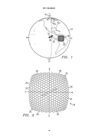
[0012] Figure 1 illustrates a satellite 12 orbiting the earth 14 in a low earth orbit 16 and projecting a satellite footprint
18 onto a fixed grid of ground-based cells 20. The low earth orbit (LEO) satellite 12 forms part of a constellation of similar
satellites that provide continuous coverage for the ground-based cells 20. In the constellation, the satellites are spaced
apart in a plurality of orbital planes, with each orbital plane having a necessary number of satellites to provide continual
coverage for the cells underlying that orbital plane. Thus, each satellite 12 immediately follows another satellite in its
orbital plane and is itself immediately followed by still another satellite in that orbital plane. In one embodiment, for
example, the constellation includes twenty-four (24) orbital planes with twelve (12) satellites in each orbital plane. In this
exemplary embodiment, each satellite has an altitude of 1,350 kilometers, a footprint, or coverage area, 18, that is 1,660
kilometers by 1,660 kilometers, and an orbital period of about 112 minutes. It will be understood that the type, number,
and orbital planes for the satellites 12 may be suitably varied.
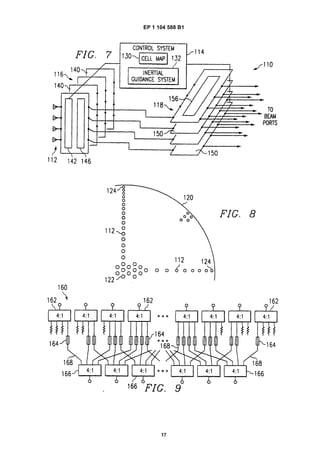
[0013] FIGURE 2 illustrates details of the ground-based cells 20 within the footprint 18. For the exemplary embodiment
in which the footprint 18 is 1,660 kilometers by 1,660 kilometers in size, the footprint 18 includes 725 hexagonal-shaped
cells 20. Each hexagonal cell is 78.7 kilometers across. The size and shape of the ground-based cells 20 may be suitably
varied so long as the cells 20 fully cover the footprint 18. For example, the footprint 18 may be tiled with square or radial
cells 20.
[0014] Due to the geometry of low earth satellites 12 above the spherical surface of the earth 14, cells 22 near the
edges of the footprint 18 have a much smaller angular size and closer angular spacing than cells 24 near the center of
the footprint 18. In the exemplary embodiment, for example, the cells 24 at the center of the footprint 18 have an angular
size of 3.5 degrees while the cells 22 near the edges of the footprint 18 have an angular size of 2.4 degrees and the
cells 25 at the corner of the footprint 18 have an angular size of 1.8 degrees.
[0015] Returning to FIGURE 1, the satellite 12 includes a multi-beam antenna system 30 for communicating directly
with a plurality of portable, mobile, and fixed terminals in the ground-based cells 20. Each beam 32 is assigned to a
ground-based cell 20. As described in more detail below, the multi-beam antenna system 30 shapes and steers each
beam 32 so that the assigned ground-based cell 20 is illuminated by that beam 32 until the next beam 32 moves into
position on that cell 20 or the next satellite 12 moves into position to illuminate the cell 20. Thus, the beams 32 are
shaped to match the ground-based cells 20 and are steered to maintain alignment with the ground-based cells 20 during
the time the satellite 12 moves one cell width along its orbit. After the satellite 12 has moved one cell width, the beams
32 are each ratcheted forward one cell width in the direction of flight and beams 32 are reassigned to the next set of
cells in the flight direction. The set of cells 20 dropped by the satellite 12 are picked up by a following satellite 12. In
this way, continuous coverage for the ground-based cells 12 is maintained. For the exemplary embodiment, the beams
32 are circular to match cells 24 near the center of the footprint 18 and elliptical to match cells 22 near the edge of the
footprint 18.
[0016] FIGURES 3-6 illustrate details of an antenna system 40 for the low earth orbit satellite 12 in accordance with](https://image.slidesharecdn.com/ep1104588b1-140520075326-phpapp01/85/Ep1104588-b1-IMPROVED-TWO-DIMENSIONALLY-STEERED-ANTENNA-SYSTEM-3-320.jpg)
![EP 1 104 588 B1
4
5
10
15
20
25
30
35
40
45
50
55
one embodiment of the present invention. In this embodiment, the antenna system 40 uses a planar lens system to
focus signals received from the ground-based cells 20. As used herein, signal means signal received from ground-based
cells 20 and any signal generated or formed based on such signals. A planar lens system is a lens system that uses
one or more planar lenses.
[0017] Referring to FIGURE 3, the antenna system 40 includes a plurality of radiating elements 42, a control system
44, a first set of array elements 46, and a second set of array elements 48. The radiating elements 42 receive component
beam signals for the ground-based cells 20. As described in more detail below, the control system 44 controls steering
of the component beams, which is performed by the first and second set of array elements 46 and 48.
[0018] The control system 44 includes a cell map 50 and an inertial guidance system 52. The cell map 50 stores
information for each ground-based cell 20 within the orbital path of the satellite 12. The cell information includes the
identification, location, and center of each cell 20. The inertial guidance system 52 tracks the position of the satellite 12
including its altitude, latitude, and longitude. The control system 44 uses the satellite positioning information along with
the cell map information to calculate an angle for each beam 32 to its assigned cell 20. Based-on this angle, the control
system 44 determines the weight that should be given to each component beam to steer the beams 32. This information
is communicated to the first and second set of array elements 46 and 48 which weigh and combine the component
beams accordingly.
[0019] For the embodiment of FIGURES 3-6, the first set of array elements 46 steer the beams 32 in a first vertical
direction and the second set of array elements 48 steer the beams 32 in a second horizontal direction. In this embodiment,
the control system 44 provides information to the first set of array elements 46 for steering in the first direction and
information to the second set of array elements 48 for steering the beams 32 in the second direction. It will be understood
that the first and second directions may be otherwise oriented with respect to each other and that the control system 44
may provide other or different information to the array elements 46 and 48 to control beam 32 steering.
[0020] The first set of array elements 46 includes a plurality of discrete elements 60. Each element 60 includes an
array of low noise amplifiers (LNA) 62, a first planar lens 64, and a first steering system 66. The low noise amplifiers 62
amplify the component beam signals received by the radiating elements 42.
[0021] The first planar lens 64 is a parallel plate or other suitable lens having two-dimensional characteristics. The
first planar lens 64 is a Stripline Rotman lens, bi-focal pillbox lens, or other suitable two-dimensional lens. A Rotman
lens is preferred because it has three focal points and thus better performance. For frequencies in the upper microwave
region, the Rotman lens is constructed using microwave circuit board materials such as Duroid made by Rogers Corp.
or similar materials.
[0022] FIGURE 4 illustrates a Stripline Rotman lens 70 for use as the first planar lens 64 in accordance with one
embodiment of the present invention. Referring to FIGURE 4, the Stripline Rotman lens 70 includes a plurality of striplines
72 of varying lengths that focus the component beams in the first direction. Feed elements 74 at the bottom of the Rotman
lens 70 collect the component beams that have been focused in the first direction.
[0023] In accordance with one aspect of the present invention, the feed elements 74 are non-uniform in size and
spacing in order to shape the beams 32 in the first direction to match the angular size and the angular spacing of the
ground-based cells 20 in the first direction. The beams 32 match the angular size of the ground-based cells 20 when
they closely approximate the size of the cell as seen by the antenna system 40. In particular, feed elements 76 near the
center of the Rotman lens 70 that correspond to cells 24 near the center of the footprint 18 are larger and spaced further
apart than feed elements 78 at the edges of the Rotman lens 70 that correspond to cells 22 near the edge of the footprint
18 in accordance with the angular size of the cells 20. In one embodiment, the feed elements 74 are sized an spaced
such that a substantially equal number of component beams are maintained for each ground-based cell 20. The particular
size and spacing of the feed elements 74 may vary depending on the lens type, footprint size, cell size and shape, and
other suitable criteria. By varying the size and spacing of feed elements 74, the component beams may be shaped
without phase shifting. Accordingly, the complexity and cost of the antenna system 40 is reduced. In addition, the total
number of component beams needed to cover the footprint 18 is reduced, which correspondingly reduces the number
of feed elements 74 and other components in the beam-forming network.
[0024] Returning to FIGURE 3, the first steering system 66 is operable to steer a beam 32 for a ground-based cell 20
in the first direction by weighing component beams associated with the ground-based cell 20 based on a position of the
antenna system 40 relative to the ground-based cell 20 in the first direction. As previously described, this information is
provided by the control system 44. The term based on the position of the antenna system 40 includes positions based
on the position of any suitable element of the antenna system 40 as well as other elements of the satellite 12 or other
platform offset from the antenna system 40 such that the beam steering information can be derived. Beams and other
signals are associated with a ground-based cell 20 when that beam or signal is weighed, formed from, or otherwise used
in forming, shaping, or steering the beam 32 for the cell 20.
[0025] FIGURE 5 illustrates details of the first steering system 66 in accordance with one embodiment of the present
invention. In this embodiment, the first steering system 66 is an amplitude modulator 80. The amplitude modular 80
modulates the amplitude and combines the component beams to steer the beams 32 in the first direction.](https://image.slidesharecdn.com/ep1104588b1-140520075326-phpapp01/85/Ep1104588-b1-IMPROVED-TWO-DIMENSIONALLY-STEERED-ANTENNA-SYSTEM-4-320.jpg)
![EP 1 104 588 B1
5
5
10
15
20
25
30
35
40
45
50
55
[0026] Referring to FIGURE 5, the amplitude modulator 80 includes a plurality of splitters 82, attenuators 84, and
combiners 86. The splitters 82 split the component beams onto four (4) intermediate paths 88 that are each cross-
connected to different combiners 86 via the attenuators 84. As used herein, the term each means each of at least a
subset of the specified elements. At the edge of the amplitude modulator 80, some of the intermediate paths 88 are
grounded and thus not used in accordance with the component beam combination scheme of the amplitude modulator
80. For example, in the illustrated embodiment, splitters 82 at the edge of the amplitude modulator 80 have three (3) of
their intermediate paths 88 grounded, the next set of splitters 82 in from the edge have two (2) of their intermediate
paths 88 grounded, the next set of splitters 82 in from the edge have one (1) intermediate path 88 grounded. The
remaining splitters 82 have all of their intermediate paths 88 cross-connected with dividers 86. It will be understood that
other or different suitable combination schemes may be used. For example, combination schemes of 3:1 and 5:1 may
be used. In addition, variable combination schemes may be used.
[0027] The attenuators 84 modulate the amplitude of signals on the intermediate paths 88 in accordance with control
information provided by the control system 44. The term attenuators includes variable gain amplifiers and other suitable
devices operable to adjust the amplitude of a signal. The attenuators 84 may be implemented as digital or analog circuits.
The attenuator range should match the sidelobe levels for the beams 32. Resolution and accuracy of the amplitude
controls may be varied as a function of the sidelobe and beam steering accuracy requirements.
[0028] For amplitude modulation in the exemplary embodiment, component beams are indexed with (p,q) peaks located
at Up, Vp. Beam spacing are ΔUp and ΔVq in the N-S (first direction) and E-W (second direction) direction respectively.
For a blend of at least three (3) beams in each of the first and the second directions, the control system 44 determines
amplitude weighing based on the following equations:
If |u-Up| ≤2nup and |v-Vq| ≤2nvq
Then
Else Ap,q=0
where: Ap,q is the amplitude of the (p,q) beam; and up and vq are coordinates of the center of the cell.
[0029] If the shaping function is constrained to be separable then for beams within pε[m, m+1, ...m+M-1] and qε[n,
n+1, ...n+N-1]:
Else Bp,q=0.
[0030] The combined steering and shaping function will then be:
where: (u0, v0) is the vector to the center of a cell.
[0031] The amplitude modulated and combined component beams form intermediate beams that are focused and
steered in the first direction. The intermediate beams from each element 60 of the first array of elements 46 are fed into
separate elements 90 of the second set of array elements 48. Each element 90 of the second array includes a second
planar lens 94 and a second steering system 96. The second planar lens 94 is a Rotman lens 70 as previously described
in connection with the first planar lens 64. In this case, the Rotman lens 70 focuses and shapes the intermediate beams
in the second direction.
[0032] The second steering system 96 is operable to steer the beams 32 for a ground-based cell 20 in the second](https://image.slidesharecdn.com/ep1104588b1-140520075326-phpapp01/85/Ep1104588-b1-IMPROVED-TWO-DIMENSIONALLY-STEERED-ANTENNA-SYSTEM-5-320.jpg)
![EP 1 104 588 B1
6
5
10
15
20
25
30
35
40
45
50
55
direction by weighing intermediate beams associated with the ground-based cell 20 based on a position of the antenna
system 40 relative to the ground-based cell 20 in the second direction. The first steering system 96 is an amplitude
modulator 80 as previously described in connection with the first steering system 66. The amplitude modulator 80
modulates and combines the intermediate beams in accordance with control information provided by the control system
44. In this case, the amplitude modulator 80 steers beams 32 in the second direction. Thus, the resulting beams 32 are
fully steered and shaped for each ground-based cell 20.
[0033] The amplitude modulator 80 provides smooth continuous steering for the beams 32 in both the first and second
directions. The amplitude modulator 80 is operable to scan each beam 32 a full +/- one (1) beam width, or cell width, to
take into account wobble of the satellite 12 and other factors and ensure that the beams 32 can maintain alignment with
the ground-based cells 20 during the time the beam 32 is assigned to the cell 20. As previously described, after the
satellite 12 moves one cell width, the beams 32 are each ratcheted forward one cell width in the direction of flight and
the beams 32 are reassigned to the next set of cells in the flight direction. The set of cells 20 dropped by the satellite
12 are picked up by a trailing satellite 12 in the orbital plane. In this way, continuous coverage is maintained for the
ground-based cells 20.
[0034] FIGURE 6 is a schematic diagram illustrating packaging of the antenna system 40 in accordance with one
embodiment of the present invention. In this embodiment, the first set of array elements 46 are packaged in a first set
of slats 100 and the second set of array elements 48 are packaged in a second perpendicular set of slats 102. The slats
100 and 102 each include a stripline circuit 104 formed from two circuit layers. Components of the array elements 46
and 48 are entirely fabricated within the two circuit layers 105. Preferably, the circuit layers each include a patterned
conductor generally isolated between dielectric layers and shielded to minimize interference with the beam-forming
network.
[0035] Referring to FIGURE 6, in the stripline circuits 104, the striplines 72 for the Rotman lens 70 and the splitters
82 and combiners 86 for the amplitude modulator 80 are formed in the first circuit layer. The remainder of the Rotman
lens 70 including the feed elements 74 are formed in the second circuit layer. The intermediate paths 88 are formed in
both circuit layers and arecross-connected byinterconnectsextendingbetween thecircuit layers. The low noise amplifiers
62 are fabricated on the first circuit layer for the first set of slats 100.
[0036] The stripline circuits 104 are mounted to a cold board 106 which provides support and heat transfer for the
stripline circuit 104. If the antenna system 40 is polarized to increase capacity, a corresponding set of stripline circuits
108 may be mounted to an opposite side of a cold board 106. Accordingly, the beam-forming and steering network can
be located internally to a satellite or other platform with only radiating elements 42 protruding from the base. The planar
slats are compact, light weight, and can be efficiently packed together. Accordingly, they are ideal for satellite and other
applications that are size and weight sensitive. In addition, because the elements 60 and 90 are each fabricated entirely
on only two circuit layers, the beam-forming and steering network is relatively inexpensive to fabricate.
[0037] For the exemplary embodiment, the satellite 12 includes sixty-two (62) slats 100 for the first set of array elements
46 and twenty-five (25) slats 104 for the second set of array elements 148. Slats 100 each include sixty-two (62) striplines
72 input to the Rotman lens 70 and twenty-eight (28) feed elements 74 output from the Rotman lens 70. The amplitude
modulators 80 include twenty-eight (28) inputs and twenty-five (25) outputs. The slats 102 each include the Rotman lens
70 with sixty-two (62) stripline 72 inputs and thirty-two (32) feed elements 74 outputs. The amplitude modulator 80
includes thirty-two (32) inputs and twenty-nine (29) outputs for a total of seven hundred twenty-five (725) beams 32. The
beams 32 are passed onto beam ports in the satellite 12 for processing.
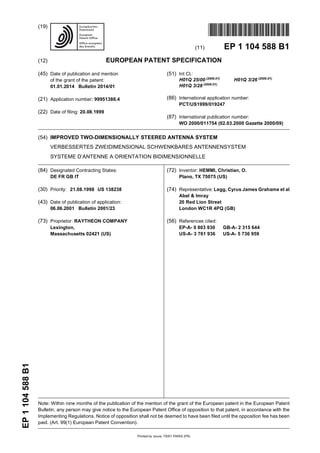
[0038] FIGURES 7-9 illustrate details of an antenna system 110 for the low earth orbit satellite 12 in accordance with
another embodiment of the present principle. The embodiments relating to figures 7-9 are not embodiments of the
claimed invention. In this embodiment, the antenna system 110 uses a spherical dielectric lens to focus signals received
from the ground-based cells 20. The spherical dielectric lens is a Luneberg or other suitable symmetrical lens. The
Luneberg lens is made from concentric shells of dielectric material. The first shell has a nominal dielectric constant of
1.0, the center core has a dielectric constant of 2.0, and the intermediate shells vary uniformly between 1.0 and 2.0.
[0039] Referring to FIGURE 7, the antenna system 110 includes a plurality of feed elements 112, a control system
114, a first set of array elements 116 and a second set of array elements 118. As described in more detail below, the
feed elements 112 receive component beam signals for the ground-based cells 20. The control system 114 controls
steering of the component beams, which is performed by the first and second array of elements 116 and 118.
[0040] Referring to FIGURE 8, the feed elements 112 are mounted to a surface of a Luneberg lens 120 opposite the
field of view of the lens 120 to receive component beams focused by the lens 120. In accordance with one aspect, the
feed elements 112 are non-uniform in size and spacing in order to shape the beams 32 to match the angular size of the
ground-based cells. In particular, feed elements corresponding to cells 22 at the edge of the footprint 18 are smaller and
spaced more closely together than feed elements 112 corresponding to cells 24 at the center of the footprint 18. In one
embodiment, the feed elements 112 are sized and spaced such that a substantially equal number of component beams
are maintained for each ground-based cell 20. The particular size and spacing of the feed elements 112 may vary
depending on the lens type, footprint size, cell size and shape, and other suitable criteria. By varying the size and spacing](https://image.slidesharecdn.com/ep1104588b1-140520075326-phpapp01/85/Ep1104588-b1-IMPROVED-TWO-DIMENSIONALLY-STEERED-ANTENNA-SYSTEM-6-320.jpg)
![EP 1 104 588 B1
7
5
10
15
20
25
30
35
40
45
50
55
of the feed elements 112, the components beams may be shaped without phase shifting. In addition, the total number
of component beams needed to cover the footprint 18 is reduced by about one-half, which correspondingly reduces the
number of feed elements 112 and other components in the beam-forming network.
[0041] Returning to FIGURE 7, the control system 114 includes a cell map 130 and an inertial guidance system 132
as previously described in connection with the control system 44. The control system 114 uses the satellite positioning
information of the interial guidance system 132 along with the cell map 130 information to calculate an angle for each
beam 32 to its assigned cell 20. Based on this angle, the control system 114 determines the weight that should be given
to each component beam to steer the beams 32. This information is communicated to the first and second set of array
elements 116 and 118 which weigh and combine the component beams accordingly.
[0042] For the embodiment of FIGURES 7-9, the first set of array elements 116 steer the beams 32 in a first vertical
directionandthe secondset of arrayelements 118 steer thebeams32in asecond horizontaldirection. In thisembodiment,
the control system 114 provides information to the first set of array elements 116 for steering the beams 32 in the first
direction and information to the second set of array elements 118 for steering the beams 32 in the second direction.
[0043] The first set of array elements 116 include a plurality of discrete elements 140. Each element 140 includes an
array of low noise amplifiers (LNA) 142 and a first steering system 146. The low noise amplifiers 142 amplify the
component beams as previously described in connection with the low noise amplifiers 62. The second set of array
elements 118 includes a plurality of discrete elements 150 each having a second steering system 156. The components
of the first and second set of array elements may be packaged into stacked slats as previously described in connection
with first and second array elements 46 and 48. In this embodiment, however, the spherical lens is separate.
[0044] The first steering system 146 is operable to steer the beam 32 for a ground-based cell 20 in the first direction
by weighing component beams associated with the ground-based cell 20 based on a position of the antenna system
110 relative to the ground-based cell 20 in the first direction. The second steering system 156 is operable to steer the
beam 32 for a ground-based cell 20 in the second direction by weighing component beams associated with the ground-
based cell 20 based on a position of the antenna system 110 relative to the ground-based cell 20 in the second direction.
As previously described, control information for the steering systems 146 and 156 is provided by the control system 114.
[0045] FIGURE 9 illustrates details of the first and second steering systems 146 and 156 in accordance with one
embodiment. In this embodiment, the first and second steering systems 146 and 156 are each an amplitude modulator
160. The amplitude modulator 160 modulates the amplitude of the intermediate beams and combines the modulated
beams to steer the beams 32 in the first and second directions as previously described in connection with the amplitude
modulator 80.
[0046] Referring to FIGURE 9, the amplitude modulator 160 includes a plurality of splitters 162, attenuators 164, and
combiners 166. The splitters 162 split the component beams into four (4) intermediate paths 168 that are each cross-
connected to different combiners 166 via the attenuators 164. Intermediate paths 168 may be grounded for splitters 162
near the edge of the amplitude modulator 160 as previously described in connection with the amplitude modulator 80.
[0047] The attenuators 164 modulate the amplitude of the signals on the intermediate paths 168 in accordance with
control information provided by the control system 114. Accordingly, as previously described in connection with the
amplitude modulator 80, the amplitude modulator 160 provides smooth continuous steering for beams 32 in both the
first and second directions. The amplitude modulator 160 is operable to scan each beam 32 a full +/- one (1) beam width,
or cell width, to ensure that the beams 32 can maintain alignment with the ground-based cells 20 during the time the
beam 32 is assigned to the cell 20.
[0048] In addition to the low earth orbit satellite 12, the present invention may be used in connection with other systems
that require multiple beams to be steered. For example, the present invention can be used for geosynchronous com-
munication satellites that use steerable spot beams, listening antennas such as ESM (Electronic Support Measures)
antennas, and transmit antennas such as ECM (Electronic Counter Measures) antennas. This invention can also be
used for antennas mounted on aircraft, dirigibles, or other platforms that orbit or are stationed above cites to provide
communication services. If the attenuators are replaced with fixed amplitude weights, the antenna architecture may be
used for applications that require a cluster of fixed beams, such as ground-based commercial wireless communications
systems.
[0049] Although the present invention has been described with several embodiments, various changes and modifica-
tions may be suggested to one skilled in the art. It is intended that the present invention encompass such changes and
modifications as fall within the scope of the appended claims.
Claims
1. A two-dimensionally steered antenna system (40), comprising:
a planar lens system (64, 94) operable to focus signals received from a plurality of ground-based cells (20) ;](https://image.slidesharecdn.com/ep1104588b1-140520075326-phpapp01/85/Ep1104588-b1-IMPROVED-TWO-DIMENSIONALLY-STEERED-ANTENNA-SYSTEM-7-320.jpg)