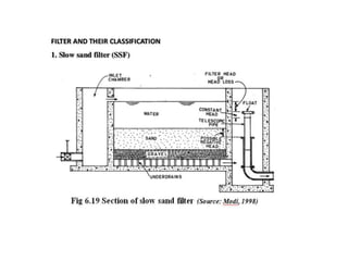
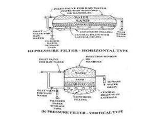
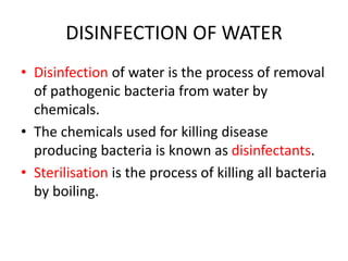
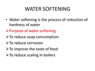
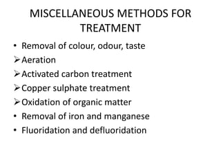
UNIT-II
CHAPTER 2.1
TREATMENT OF WATER
SEDIMENTATION
• It is the process of causing heavier solid
particles in suspension both organic and
inorganic, to settle by retaining water in a
basin
Sedimentation
THEORY OF SEDIMENTATION
• The particles heavier than water tends to
settle down due to force of gravity.
• Impurities in water are held in suspension
due to the turbulence of the moving water.
• When the velocity of flow is reduced, the
suspended particles tend to settle down at the
bottom of the tank.
• This phenomenan is known as hydraulic
subsidence.
FACTORS AFFECTING SEDIMENTATION
• Size, shape and weight of the particle
• Viscosity and temperature of water
• Surface overflow
• Surface area
• Velocity of flow
• Inlet and outlet arrangements
• Detention period
• Effective depth of settling tank
• Concentration of suspended matter
• Wind blow on the surface area of the basin
• Biological, electrical and other forces
TYPES OD SEDIMENTAION
• PLAIN SEDIMENTATION
• SEDIMENTATION WITH COAGULATION
PLAIN SEDIMENTATION
• The raw water is retained for sometime in a
basin for the suspended particles to settle
down by the action of gravity.
SEDIMENTATION WITH COAGULATION
• In this some chemical compounds called
coagulants are added to water to assist
sedimentation.
Coagulation
Classification of sedimentation tank
• Nature of working
 Fill and draw type
 Continuous flow type
• Direction of flow
 Horizontal flow basin
 Vertical or upward flow basin
 Radial flow basin
 Spiral or circumferential flow basin
• Shape
 Rectangular(horizontal flow) tanks.
 Circular (vertical, radial, circumferential flow)
tanks.
 Hopper bottom (radial flow) tanks.
FILL AND DRAW TYPE
• The raw water is allowed to rest on the basin
for sometime.
• During that time the suspended particles
settle down at the bottom.
• The clear water is drawn off and the deposits
are cleaned.
• Then the basins is refilled and the action
continues.
CONTINUOUS FLOW TYPE
• The raw water is allowed to flow through the
tank continuously with a small uniform
velocity.
• Within the detention time the suspended
particles settle down at the bottom before
they reach the exit.
• The inlets and outlets are so designed that
they cause least disturbance to the flowing
water in the tank.
HORIZONTAL FLOW BASIN
• It is a rectangular plan having length is twice
or thrice the breadth.
• The floor is given a slope to facilitate sludge
removal.
VERTICAL OR UPWARD FLOW BASIN
• It is deep and circular or rectangular with
hopper bottom.
• The raw water enters the basin vertically from
bottom through the centrally located vertical
inlet pipe.
• The suspending particle settle down at the
hopper bottom and is collected through the
sludge pipe.
RADIAL FLOW BASIN
• The water enters through the central inlet
pipe.
• The inlet pipe is enclosed with the deflector
box which deflects the flow downwards.
• Then the flow goes out radially towards the
circumference of the tank.
• During the radial flow all the settleable
particles settle down.
SPIRAL OR CIRCUMFERENCE FLOW
BASIN
• The water enters the tank through two or
three vertical slits of the inlet channel.
• A rotating arm is provided in the tank.
• It makes all the water in the tank to move
circumferentially.
• As the flow is very slow all the settleable
particles settle at the bottom of the tank.
• Clear water is drawn through weir type outlet.
DEFINITION IN COAGULATION OF
WATER
• The process of addition and mixing of
coagulants is coagulation.
• The process of addition of coagulants in
correct amount is called dosing.
• The process of floc formation is termed as
flocculation.
• The coagulation is adopted when the turbidity
of raw water exceeds 30 to 50 ppm.
Objectives of coagulants
• To unite several fine colloidal particles
together.
• To react with impurities in water and make
them to settle.
• To prepare raw water fit for filtration.
• To expedite quick sedimentation.
• To remove certain extent turbidity, organic
and inorganic matter.
COMMON COAGULANTS
• Sodium aluminate
• Ferric chloride
• Ferric sulphates
• Betonite clay
• Fuller’s earth
• Magnesium carbonate
• Polyelectolytes
COAGULANT FEEDERS
• The coagulants may be fed in powder form
(dry feeding) or in solution form (wet feeding)
Dry feeders
Wet feeders
DRY FEEDERS
WET FEEDERS
COAGULANT MIXERS
• The success of floc formation mainly depends
upon the through mixing of coagulant with raw
water
• The violent mixing is carried out by the following
devices
Centrifugal pump
Compressed air
Mixing channel
Mixing basin
Mixing basins with baffle walls
• Horizontal or round the end type
• Vertical or over and under the baffle type
Mixing basins with mechanical devices
• Flash mixers
• Flocculators
DOSAGE OF COAGULANTS
• Kind of coagulants
• Amount of coagulants
• Time of mixing
• Violence of agitation
• Time of settlement
• Amount and character of colour
• Turbidity of water
• Ph of water
• Temperature of water
FILTRATION
• Filtration is the process of passing the water
through filter beds.
• Filtration is the most important stage in the
purification of water.
• Filtration removes colour, odour, turbidity and
pathogenetic bacteria from water
• It also changes the chemical characteristics of
water.
THEORY OF FILTRATION
Mechanical straining
Sedimentation and absorption
Biological metabolism of bacterial action
Electrolytic changes
FILTER SAND
• Sand having effective size of 0.25 to 0.35 mm
are used for slow sand filters
• Sand having effective size of 0.35 to 0.60 mm
are used for rapid sand filters
• For slow sand filters the depth of sand bed is
0.60 to 1m.
• For slow sand filters the depth of sand bed is
0.60 to 0.9m.
TYPES OF FILTERS
• Slow sand filters
• Rapid sand filters
• Pressure filters
DISINFECTION OF WATER
• Disinfection of water is the process of removal
of pathogenic bacteria from water by
chemicals.
• The chemicals used for killing disease
producing bacteria is known as disinfectants.
• Sterilisation is the process of killing all bacteria
by boiling.
METHODS OF DISINFECTION
• Boiling
• Excess lime treatment
• Iodine and bromine treatment
• Ozone treatment
• Potassium permanganate treatment
• Silver treatment
• Ultra violet ray treatment
CHLORINATION
• Chlorination is the treatment of water with
chlorine for disinfection of water.
• Chlorination not only disinfectants, but also
removes colour, odour, unpleasant taste and
prevent the growth of weeds in water.
FORMS OF CHLORINATION
• As bleaching powder
• As chloromines
• As chlorine-di-oxide
• As free chlorine gas
• As liquid chlorine
• Dosage of chlorine
• Residual chlorine
• Contact period
WATER SOFTENING
• Water softening is the process of reduction of
hardness of water
Purpose of water softening
To reduce soap consumption
To reduce corrosion
To improve the taste of food
To reduce scaling in boilers
HARDNESS OF WATER
• It is caused by the presence of certain salts of
calcium and magnesium dissolved in water.
• It s the characteristic which prevents the
lathering of soap.
• TYPES OF HARDNESS
Temporary hardness
Permanent hardness
REMOVAL OF HARDNESS
• Removal of temporary hardness
• Removal of permanent hardness
Lime – soda process
Zeolite process
Demineralisation
MISCELLANEOUS METHODS FOR
TREATMENT
• Removal of colour, odour, taste
Aeration
Activated carbon treatment
Copper sulphate treatment
Oxidation of organic matter
• Removal of iron and manganese
• Fluoridation and defluoridation
REVERSE OSMOSIS PROCESS
CHAPTER 2.2
DISTRIBUTION SYSTEM
GENERAL REQUIREMENTS
• It should be capable of supplying water in
adequate quantities.
• It should meet the demand of water supply for
fire fighting purposes.
• It should be economical in its design, layout and
construction.
• It should be easy and simple to operate and
repair.
• It should be safe against any future pollution of
water
• It should be water tight.
• It should be safe as not to cause the failure of
the pipe line.
• It should provide free circulation of water.
• The sanitation of the water distribution area
should be good so that the possibilities of
pollution are remote during repairs or
replacement of pipes.
DIFFERENT SYSTEMS OF SUPPLYING
WATER
Systems of conveyance and distribution
Systems of water supply
Systems of distribution layout
SYSTEMS OF CONVEYANCE AND
DISTRIBUTION
• Gravity system
• Pumping system
• Combined pumping and gravity system
SYSTEM OF WATER SUPPLY
• Continuous system
• Intermittent system.
SYSTEM OF DISTRIBUTION LAYOUT
• Dead end or tree system
• Grid iron system
• Circular or ring system
• Radial system
SERVICE RESERVOIRS
• Service reservoir are also known as
distribution reservoir.
• They are the tanks constructed to store
treated water which may be used when
required.
FUNCTIONS OF SERVICE RESERVOIR
• To store water for emergencies like breakdown
of pumps, fires, power supply failures etc…
• To facilitate constant rate of pumping and thus
reduce pumping hours.
• Under gravity system of supply, to minimise
the diameter of mains.
• To make the design and construction of
treatment units and distribution system
economical.
TYPES OF SERVICE RESERVOIR
• SURFACE RESERVOIR
• ELEVATED RESERVOIR
CAPACITY OF SERVICE RESERVOIR
Balancing storage
Breakdown storage
Fire storage
FACTORS AFFECTING CAPACITY OF
RESERVOIRS
• The variation between maximum and
minimum demands.
• The reserve required for emergencies like fire
or breakdown of pumps.
• The standby pumping capacity.
• Interconnections in the distribution mains.

ENVIRONMENTAL ENGINEERING & POLLUTION CONTROL

  • 1.
  • 2.
  • 3.
    SEDIMENTATION • It isthe process of causing heavier solid particles in suspension both organic and inorganic, to settle by retaining water in a basin
  • 4.
  • 5.
    THEORY OF SEDIMENTATION •The particles heavier than water tends to settle down due to force of gravity. • Impurities in water are held in suspension due to the turbulence of the moving water. • When the velocity of flow is reduced, the suspended particles tend to settle down at the bottom of the tank. • This phenomenan is known as hydraulic subsidence.
  • 6.
    FACTORS AFFECTING SEDIMENTATION •Size, shape and weight of the particle • Viscosity and temperature of water • Surface overflow • Surface area • Velocity of flow • Inlet and outlet arrangements • Detention period
  • 7.
    • Effective depthof settling tank • Concentration of suspended matter • Wind blow on the surface area of the basin • Biological, electrical and other forces
  • 8.
    TYPES OD SEDIMENTAION •PLAIN SEDIMENTATION • SEDIMENTATION WITH COAGULATION
  • 9.
    PLAIN SEDIMENTATION • Theraw water is retained for sometime in a basin for the suspended particles to settle down by the action of gravity.
  • 10.
    SEDIMENTATION WITH COAGULATION •In this some chemical compounds called coagulants are added to water to assist sedimentation.
  • 11.
  • 12.
    Classification of sedimentationtank • Nature of working  Fill and draw type  Continuous flow type • Direction of flow  Horizontal flow basin  Vertical or upward flow basin  Radial flow basin  Spiral or circumferential flow basin
  • 13.
    • Shape  Rectangular(horizontalflow) tanks.  Circular (vertical, radial, circumferential flow) tanks.  Hopper bottom (radial flow) tanks.
  • 14.
    FILL AND DRAWTYPE • The raw water is allowed to rest on the basin for sometime. • During that time the suspended particles settle down at the bottom. • The clear water is drawn off and the deposits are cleaned. • Then the basins is refilled and the action continues.
  • 16.
    CONTINUOUS FLOW TYPE •The raw water is allowed to flow through the tank continuously with a small uniform velocity. • Within the detention time the suspended particles settle down at the bottom before they reach the exit. • The inlets and outlets are so designed that they cause least disturbance to the flowing water in the tank.
  • 18.
    HORIZONTAL FLOW BASIN •It is a rectangular plan having length is twice or thrice the breadth. • The floor is given a slope to facilitate sludge removal.
  • 19.
    VERTICAL OR UPWARDFLOW BASIN • It is deep and circular or rectangular with hopper bottom. • The raw water enters the basin vertically from bottom through the centrally located vertical inlet pipe. • The suspending particle settle down at the hopper bottom and is collected through the sludge pipe.
  • 21.
  • 22.
    • The waterenters through the central inlet pipe. • The inlet pipe is enclosed with the deflector box which deflects the flow downwards. • Then the flow goes out radially towards the circumference of the tank. • During the radial flow all the settleable particles settle down.
  • 23.
  • 24.
    • The waterenters the tank through two or three vertical slits of the inlet channel. • A rotating arm is provided in the tank. • It makes all the water in the tank to move circumferentially. • As the flow is very slow all the settleable particles settle at the bottom of the tank. • Clear water is drawn through weir type outlet.
  • 25.
    DEFINITION IN COAGULATIONOF WATER • The process of addition and mixing of coagulants is coagulation. • The process of addition of coagulants in correct amount is called dosing. • The process of floc formation is termed as flocculation. • The coagulation is adopted when the turbidity of raw water exceeds 30 to 50 ppm.
  • 26.
    Objectives of coagulants •To unite several fine colloidal particles together. • To react with impurities in water and make them to settle. • To prepare raw water fit for filtration. • To expedite quick sedimentation. • To remove certain extent turbidity, organic and inorganic matter.
  • 27.
    COMMON COAGULANTS • Sodiumaluminate • Ferric chloride • Ferric sulphates • Betonite clay • Fuller’s earth • Magnesium carbonate • Polyelectolytes
  • 28.
    COAGULANT FEEDERS • Thecoagulants may be fed in powder form (dry feeding) or in solution form (wet feeding) Dry feeders Wet feeders
  • 29.
  • 30.
  • 31.
    COAGULANT MIXERS • Thesuccess of floc formation mainly depends upon the through mixing of coagulant with raw water • The violent mixing is carried out by the following devices Centrifugal pump Compressed air Mixing channel Mixing basin
  • 32.
    Mixing basins withbaffle walls • Horizontal or round the end type • Vertical or over and under the baffle type
  • 34.
    Mixing basins withmechanical devices • Flash mixers • Flocculators
  • 36.
    DOSAGE OF COAGULANTS •Kind of coagulants • Amount of coagulants • Time of mixing • Violence of agitation • Time of settlement • Amount and character of colour • Turbidity of water • Ph of water • Temperature of water
  • 37.
    FILTRATION • Filtration isthe process of passing the water through filter beds. • Filtration is the most important stage in the purification of water. • Filtration removes colour, odour, turbidity and pathogenetic bacteria from water • It also changes the chemical characteristics of water.
  • 38.
    THEORY OF FILTRATION Mechanicalstraining Sedimentation and absorption Biological metabolism of bacterial action Electrolytic changes
  • 40.
    FILTER SAND • Sandhaving effective size of 0.25 to 0.35 mm are used for slow sand filters • Sand having effective size of 0.35 to 0.60 mm are used for rapid sand filters • For slow sand filters the depth of sand bed is 0.60 to 1m. • For slow sand filters the depth of sand bed is 0.60 to 0.9m.
  • 41.
    TYPES OF FILTERS •Slow sand filters • Rapid sand filters • Pressure filters
  • 46.
    DISINFECTION OF WATER •Disinfection of water is the process of removal of pathogenic bacteria from water by chemicals. • The chemicals used for killing disease producing bacteria is known as disinfectants. • Sterilisation is the process of killing all bacteria by boiling.
  • 47.
    METHODS OF DISINFECTION •Boiling • Excess lime treatment • Iodine and bromine treatment • Ozone treatment • Potassium permanganate treatment • Silver treatment • Ultra violet ray treatment
  • 48.
    CHLORINATION • Chlorination isthe treatment of water with chlorine for disinfection of water. • Chlorination not only disinfectants, but also removes colour, odour, unpleasant taste and prevent the growth of weeds in water.
  • 49.
    FORMS OF CHLORINATION •As bleaching powder • As chloromines • As chlorine-di-oxide • As free chlorine gas • As liquid chlorine
  • 50.
    • Dosage ofchlorine • Residual chlorine • Contact period
  • 51.
    WATER SOFTENING • Watersoftening is the process of reduction of hardness of water Purpose of water softening To reduce soap consumption To reduce corrosion To improve the taste of food To reduce scaling in boilers
  • 52.
    HARDNESS OF WATER •It is caused by the presence of certain salts of calcium and magnesium dissolved in water. • It s the characteristic which prevents the lathering of soap. • TYPES OF HARDNESS Temporary hardness Permanent hardness
  • 53.
    REMOVAL OF HARDNESS •Removal of temporary hardness • Removal of permanent hardness Lime – soda process Zeolite process Demineralisation
  • 54.
    MISCELLANEOUS METHODS FOR TREATMENT •Removal of colour, odour, taste Aeration Activated carbon treatment Copper sulphate treatment Oxidation of organic matter • Removal of iron and manganese • Fluoridation and defluoridation
  • 55.
  • 56.
  • 57.
    GENERAL REQUIREMENTS • Itshould be capable of supplying water in adequate quantities. • It should meet the demand of water supply for fire fighting purposes. • It should be economical in its design, layout and construction. • It should be easy and simple to operate and repair. • It should be safe against any future pollution of water
  • 58.
    • It shouldbe water tight. • It should be safe as not to cause the failure of the pipe line. • It should provide free circulation of water. • The sanitation of the water distribution area should be good so that the possibilities of pollution are remote during repairs or replacement of pipes.
  • 59.
    DIFFERENT SYSTEMS OFSUPPLYING WATER Systems of conveyance and distribution Systems of water supply Systems of distribution layout
  • 60.
    SYSTEMS OF CONVEYANCEAND DISTRIBUTION • Gravity system • Pumping system • Combined pumping and gravity system
  • 61.
    SYSTEM OF WATERSUPPLY • Continuous system • Intermittent system.
  • 62.
    SYSTEM OF DISTRIBUTIONLAYOUT • Dead end or tree system • Grid iron system • Circular or ring system • Radial system
  • 63.
    SERVICE RESERVOIRS • Servicereservoir are also known as distribution reservoir. • They are the tanks constructed to store treated water which may be used when required.
  • 64.
    FUNCTIONS OF SERVICERESERVOIR • To store water for emergencies like breakdown of pumps, fires, power supply failures etc… • To facilitate constant rate of pumping and thus reduce pumping hours. • Under gravity system of supply, to minimise the diameter of mains. • To make the design and construction of treatment units and distribution system economical.
  • 65.
    TYPES OF SERVICERESERVOIR • SURFACE RESERVOIR • ELEVATED RESERVOIR
  • 66.
    CAPACITY OF SERVICERESERVOIR Balancing storage Breakdown storage Fire storage
  • 67.
    FACTORS AFFECTING CAPACITYOF RESERVOIRS • The variation between maximum and minimum demands. • The reserve required for emergencies like fire or breakdown of pumps. • The standby pumping capacity. • Interconnections in the distribution mains.