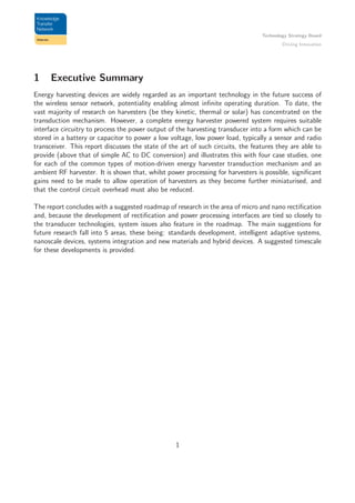
This document discusses electrical rectification in vibrational energy harvesting technologies. It begins with an overview of simple half-wave and full-wave rectifier circuits used to convert alternating current (AC) output from energy harvesters into direct current (DC) needed to power electronic devices. The document then examines case studies of different harvester technologies, including electrostatic, piezoelectric, electromagnetic, and radio frequency harvesting. It concludes by recommending areas for future research, such as developing standards, creating adaptive intelligent systems, advancing nanoscale devices, improving systems integration, and exploring new materials and hybrid devices.


![Technology Strategy Board
Driving Innovation
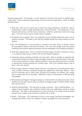
2 Energy Harvesting technologies
The purpose of this report is to discuss the state of the art and future directions for nano-rectification,
which is the processing of the AC outputs of energy harvesting systems into regulated low voltage
DC, suitable for powering an ultra-low power sensor node, for example [1], [2], [3]. As will be seen,
the challenges of AC to DC conversion at low voltages and low power levels can be significant, and
this specific challenge means that, in some cases, energy harvester transducer design is modified
away from the optimal configuration in order to make passive rectification easier [4].
This report takes its steer from the simple fact that high performance solutions may be developed
for energy harvesting applications only if the complete system is considered holistically [5].
By way of introduction, a typical motion-driven energy harvesting system (of the piezoelectric type) is
shown schematically in Figure 1. Here, the piezoelectric material and mechanical structure provides
energy in the form of a charge separation (i.e. a charged capacitor) to the interface circuit. The
oscillation of the beam means that the voltage developed on the piezoelectric capacitor contains
purely AC components and thus some form of rectification is necessary if the system is to drive a
low-power DC load. Consequently the interface circuit in Figure 1 can, in its simplest form, be a
diode rectifier. The generated energy is then stored (in a capacitor or battery) and regulated before
being supplied to a low-power load. As energy is converted from a mechanical to electrical form by
the transducer and interface circuit, the mechanical motion is damped, reducing the amplitude of
the proof mass. The control of the amount of damping applied is critical to achieving high power
densities for such systems and is a key feature required of the rectifier interface.
Figure 1: A typical energy harvesting system
The circuitry which implements the AC to DC conversion process is, in its simplest form, a passive
diode rectifier. However, this may not be possible if the transducer output voltage is low and so
other solutions are required. In addition, the circuit which accomplishes the AC to DC conversion
process can also perform other tasks, such as tuning the resonant frequency of a kinetic harvester or
increasing the available damping force. Both of these additional functions can improve the system’s
power density. These and other issues related to the rectification and systems control are discussed
in this report.
3](https://image.slidesharecdn.com/11190724-fb8a-4a60-8826-0088eb365806-151110114252-lva1-app6891/85/Energy-Harvesting-Report-5-320.jpg)
![Technology Strategy Board
Driving Innovation
3 Electrical rectification
3.1 Simple circuits
There are several possible mechanical architectures of vibration based power generators [6]. In the
case of piezo-generators, the energy conversion takes place via the direct piezoelectric effect. This
is the direct generation and delivery of charge onto the electrodes of a piezoelectric material when
a stress is applied to the material. The energy conversion is maximised by a maximum deformation
(strain) of the piezoelectric material. This usually occurs at the electro-mechanical resonance of the
material. Assuming the external driving force is sinusoidal (or cyclical) in nature - as is the case
for many vibrational sources of energy - then the charge generated by the piezoelectric material is
also cyclical. The charge developed depends on the piezoelectric characteristics, its geometry and
the details of the external mechanical vibration. The mechanical vibrations, which are the source
of energy that is harvested from the environment, are not always periodic, uniform or continuous,
however. The simplest electronic interface [7] for harvesting cyclical voltages consists of a half wave
or full wave bridge rectifier (a simple diode circuit) and a smoothing capacitor, Cs, with an an
electrical load, RL connected (see Figure 2).
a
D1
Cs RL
(a)
D1
+
D2 D3
D4
Cs RL
−
(b)
Figure 2: Standard rectification interface circuits for energy harvesting, a) half wave rectifier and b)
full wave rectifier
Assuming a single-mode external mechanical vibration (the mechanical displacement u(t) is assumed
to be purely sinusoidal), then the open circuit voltage delivered by the piezo-element will also be si-
nusoidal. However, the electrical circuit that connects the piezo-generator to the load resistor affects
the output waveform of the piezo-generator. If the piezo-generator can develop sufficient voltage
such that the forward biased diodes in the bridge rectifier can operate in their conducting mode (for
silicon the switch on voltage is about 0.6 V and for germanium diodes this is about 0.3 V) then the
piezo cyclical voltage will be rectified such that the voltage across the load resistor will be unipolar
(positive going only or negative going only - depending on how the piezo-generator is connected
to the circuit), and with the addition of a smoothing capacitor this unipolar cyclical voltage will
4](https://image.slidesharecdn.com/11190724-fb8a-4a60-8826-0088eb365806-151110114252-lva1-app6891/85/Energy-Harvesting-Report-6-320.jpg)
![Technology Strategy Board
Driving Innovation
appear as a DC voltage on the load resistor. More precisely, when the output voltage across the
load resistor exceeds the absolute value of the piezoelectric device minus the 2 diode voltage drop
then the piezo is in an open circuit configuration and its voltage swings with its displacement. When
the absolute value of the piezo voltage generated is equal to or greater than the storage capacitor
voltage plus the bridge rectifier voltage drop then electrical energy is transferred to the capacitor
and load. This rather simplistic explanation is sufficient for the needs of this report and subsequent
analysis of alternative rectification strategies [8], [9]. More details are presented in section 4.2.
Improved methods for efficiently harvesting this type of mechanical-electrical energy conversion are
generally based on the reduction in the diode voltage drops associated with semiconductor rectifier
diodes (or bridge rectifiers). The simplest way of achieving this is to use a synchronous rectifier,
where diodes are replaced with MOSFETs [10]. Such synchronous rectifiers can be commutated by
active circuitry which is externally powered or powered directly from the AC input signal [11]. Several
other ways in which diode drops have been overcome involve using more sophisticated techniques,
such as those reported in [7] and [12] which are based on the parallel SSHI (synchronized switch
harvesting on inductor). These circuit configurations intermittently switch the piezoelectric onto
a resonating electrical network (LCR) for a very short time, which has the effect of increasing the
voltage output and effectively increasing the coupling coefficient of the piezomaterial. This has been
shown to accomplish gains of order times 8 in harvested power compared to the standard bridge only
configuration [12]. An extension of the parallel SSHI method has been developed [12], and others,
that is called series SSHI based upon rectification of the piezo voltage without significant voltage
drop and allows for a greater efficiency of harvesting power at much lower voltages. The series SSHI
energy harvesting circuit is shown in Figure 3 and one can see that two digital switches are placed
in series with the piezoelectric and rectifier. These switches are synchronised with the piezo charge
cycle, and when the latter is at a maximum the switches close and energy is transferred through the
rectifier to the storage capacitor. The switched voltage is actually inverted through this process and
losses can be significant. Yet another variation on this approach uses a transformer to further reduce
the effect of the voltage drop [12] where a transformer replaces the inductor in Figure 3 along with
a new diode in series with the load. In this report, a new technique, called single supply pre-biasing
will be discussed, which is superior to the SSH techniques.
More recent work has developed the synchronous switching technology and coupled this with a
voltage pre-bias to permit even greater power output of piezo energy harvesting devices [8]. The
method is particularly suited for undamped and low frequency applications but with high excitation
amplitude - such environments are typically found in foot-fall and engine vibrations for example.
Some of the original work on harvester interface circuits was in relation to electrostatic harvesters
which use variable capacitor structures to couple kinetic energy into the mechanical domain. An
early example of such work is presented in [13]. In this paper, the upper limits on voltages for op-
erating the transducer was set by the power processing electronics interface, limited by the CMOS
process, which severely reduced the power density of the system.
5](https://image.slidesharecdn.com/11190724-fb8a-4a60-8826-0088eb365806-151110114252-lva1-app6891/85/Energy-Harvesting-Report-7-320.jpg)
![Technology Strategy Board
Driving Innovation
Figure 3: Series SSHI circuit and typical waveforms - from [12].
3.2 Vibrational EH technology
Of the various sources of ambient energy, mechanical energy in the form of vibrations is present in
many environments, particularly where there is some form of machinery, and is an alternative when
light or thermal sources are not sufficient. The most common method for scavenging this energy
source is to use resonant inertial devices. Typically, this involves a resonant cantilever with a tip
mass, where accelerations arising from the vibrating source cause the tip mass to oscillate. In order
to convert the kinetic energy to electrical, three methods have been used, electromagnetic, elec-
trostatic and piezoelectric. Electrostatic, although well suited to Micro-ElectroMechanical (MEMS)
scale devices, has been less studied recently due to low power levels, whilst miniaturisation with
electromagnetic transduction is problematic because of the difficulty in producing compact coils. In
contrast, piezoelectric transduction has the potential for miniaturisation in MEMS scale devices.
3.3 Direct AC power utilisation - negating the need for rectification
One of the basic questions asked of the ‘Intelligent energy harvesting - strategies for Utilising har-
vested energy’, held on 5th May 2011 at the Institute of Materials, Minerals and Mining, 1 Carlton
House Terrace, London, was whether applications exist that do not require rectification of the cyclic
6](https://image.slidesharecdn.com/11190724-fb8a-4a60-8826-0088eb365806-151110114252-lva1-app6891/85/Energy-Harvesting-Report-8-320.jpg)
![Technology Strategy Board
Driving Innovation
• Circuits that run off AC: There is current research aimed at how one might directly power
electronic circuitry with AC rather than DC (rectified AC) power. Notably, the work of
Amirtharajah in development of AC powered circuits has interesting potential applicability to
energy harvesting technology [14]
4 Optimisation strategies: Materials, device geometry, power
systems design and electronics engineering
The performance of any energy harvesting system is highly dependent on the performance of the
transduction mechanism and the power conversion electronics. As these two subsystems are closely
linked (the very nature of a harvester is that the power extraction via a storage element must influence
the behaviour of the transducer, otherwise the very little power can be extracted) the optimisation
of the whole system is of the greatest importance. Different types of energy harvesters suffer from
different bottlenecks in technology and so here the design of harvesters and power processing cir-
cuitry will be discussed for four types of harvester: the three common motion-driven devices and an
ambient RF harvester system, highlighting the requirements of the power converter circuit and the
methods that have been identified thus far in the literature to improve system performance.
4.1 Electrostatic case study
Electrostatic harvesters gained significant interest from researchers involved in the initial MEMS
energy harvester work which took place in the late 1990s/early 2000s. The main reasons for this
interest in electrostatic devices were probably the familiarity within the MEMS community of us-
ing electrostatic comb-drives as actuators, excellent MEMS compatibility and the knowledge of
the scaling of the electrostatic force at the micro-scale, which is clearly important for harvesters
to be miniaturised [15]. However, as has been discussed here, the performance of the complete
energy harvester power system module is far more important than the performance of just the en-
ergy harvesting transduction mechanism in isolation. Recently, a comprehensive study has been
undertaken which analyses the performance of the complete electrostatic harvester system to de-
termine the upper limits on such systems as a function of excitation level and device dimensions [16].
Unless an electret is included [17], electrostatic transducers used as generators must be pre-charged
when at maximum capacitance in order to set up an electric field against which mechanical work
can be done in order to generate electrical energy. In other words, a small quantity of charge is
placed on the electrodes before the motion of the generator drives the plates apart, increasing the
energy stored in the electric field. This energy can then be transferred from the moving electrode
capacitor into a separate energy store, which could be another capacitor or a battery.
8](https://image.slidesharecdn.com/11190724-fb8a-4a60-8826-0088eb365806-151110114252-lva1-app6891/85/Energy-Harvesting-Report-10-320.jpg)
![Technology Strategy Board
Driving Innovation
There are two common methods of operating an electrostatic harvester, these being constant charge
mode and constant voltage mode. The charge-voltage cycles of the transducer in each mode is shown
in Figure 4. In constant charge mode, the moving electrodes separate with the electrodes in open
circuit, i.e. with the charge confined to the electrodes and unable to flow in an external circuit. In
constant voltage mode, the electrodes are connected directly to a fixed voltage source and as the
plates separate, charge is driven from the electrodes into the voltage source, increasing the energy
stored in that source. In each case, the attractive force between the electrodes should be set to an
optimal value [18] which maximises the mechanical work that can be done, given by (1):
FoptCZres
=
π
4
mA0 (1)
Q
VA
B
CQopp
Vpc Vmax
(a) Constant charge mode
Q
V
A
B
CQres
Vres
Qpre
Vopp
(b) Constant voltage mode
Figure 4: Idealised charge versus voltage (QV) generation cycles (from [16] with permission).
Two basic circuits which can be used to operate these QV cycles are shown in Figure 5. In Fig-
ure 5a, the variable capacitor can be pre-charged at maximum capacitance by pulsing M1 and M2
in antiphase to charge Cvar to an optimal pre-charge voltage which sets the force to that given by
(1). The plates then separate with the MOSFETs off and so the voltage on the plates increases.
M1 and M2 are then pulsed again in antiphase to transfer the energy back to the storage element.
For the constant voltage device, the circuit of Figure 5b can be used. In this circuit the MOSFETs
M3 and M4 are pulsed in order to charge Cint to a high voltage (the voltage which causes the force
on the electrodes to correspond to that given by 1). Then, pulsing M1 and M2 in antiphase allows
the variable capacitor to be charged when at maximum capacitance. As the plates separate, M1 is
held on, meaning that the large capacitor Cint holds the voltage on the variable capacitor constant
during plate separation. M3 and M4 then pulse to transfer energy back into the storage element.
The non-ideal properties of the MOSFET switches are the main cause of the performance limits
of this system. Firstly, the devices must be designed to block the voltage which is optimal for the
capacitor to operate at and whilst increasing this voltage can allow more work to be done against the
mechanical force, increases in voltage increase the specific on-resistance of the devices. Secondly,
9](https://image.slidesharecdn.com/11190724-fb8a-4a60-8826-0088eb365806-151110114252-lva1-app6891/85/Energy-Harvesting-Report-11-320.jpg)
![Technology Strategy Board
Driving Innovation
M1
M2
Ron
Cvar
Vsupply
L
Cpara
S1
Rleak
(a) Constant charge mode
M2
Cvar
Vsupply
L1 L2
M1 M3
M4CintVopp
(b) Constant voltage mode
Figure 5: Basic circuits for electrostatic harvester operation (from [16] with permission).
there is a trade-off in device area as an increased area will reduce conduction loss but will increase
off-state leakage and charge sharing when the devices are in the off-state.
Consequently, the strategy for optimising the system is to firstly calculate the optimal voltage at
which to operate the electrodes, design the MOSFETs to block this voltage and then perform an
optimisation on the device area to maximise the performance of the system. The results are shown
in Figure 6 and assume silicon is used as the semiconducting material. As can be seen, the max-
imum system effectiveness (see [19] for details on the calculation of effectiveness) is poor for the
constant charge generator over the entire operating envelope of size and accelerations, whilst the
constant voltage device can operate relatively well over a large operating range. The reason for
the poor performance of the constant charge device is mainly due to charge sharing which occurs
between the moving electrodes and the attached semiconductors causing a significant reduction in
the mechanical work done. The constant voltage device does not suffer from this problem as the
voltage across the electrodes remains constant during generation.
In order to improve the performance of the electrostatic device types, better semiconductors are
required with lower leakage and lower on-state conduction loss when operated at high voltages. It is
possible that small silicon carbide devices and diamond devices may be able to allow the performance
of these systems to be improved.
10](https://image.slidesharecdn.com/11190724-fb8a-4a60-8826-0088eb365806-151110114252-lva1-app6891/85/Energy-Harvesting-Report-12-320.jpg)
![Technology Strategy Board
Driving Innovation
10
−2
10
0
10
2
10
−1
10
0
10
1
0
0.1
0.2
0.3
0.4
0.5
Acceleration [m/s
2
]
Length of cube [mm]
SystemEffectiveness
(a) Constant charge mode
10
−2
10
0
10
2
10
−1
10
0
10
1
0
0.2
0.4
0.6
0.8
1
Acceleration [m/s
2
]
Length of cube [mm]
SystemEffectiveness
(b) Constant voltage mode
Figure 6: System Effectiveness for constant charge and constant voltage generators (from [16] with
permission).
4.2 Piezoelectric case study
The piezoelectric transduction mechanism is attractive for use in an energy harvester as it does not
require a pre-charge to operate and tends to produce terminal voltages in the range of hundreds of
mV to a few volts. The output is AC, but due to the voltage levels produced, this can usually be
rectified using a simple full-wave rectifier, typically using Schottky diodes. However, whilst such a
scheme is advantageous in terms of simplicity, robustness and low component count, it can be dif-
ficult to obtain the necessary electrical damping forces to achieve maximum power conversion from
kinetic to electrical energy. Techniques to increase the damping and maximise power generation can
be applied, by either modifying the geometry of the device by providing an active power electronic
interface to the system, or in combination, which will now be described.
For an efficient piezoelectric energy harvester the vibrational energy must be transferred into a strain
in the piezoelectric for it to be converted into electrical form. There have been several reviews of
piezoelectric energy harvesters [1] [20], [21], [6] with many proposed methods, but the most popu-
lar because of its simplicity is the fixed-free cantilever, vibrating at its fundamental flexural mode.
The strain energy in the cantilever in this mode varies linearly along the length from the maximum
at the root to zero at the end. Through the cantilever thickness, the maximum strain is at the
points furthest from the neutral axis. These principles have led to developments such as triangular
cantilevers with uniform strain along the length, and air spaced cantilevers to increase the distance
from the neutral axis [22].
The simple rectangular cantilever comprising a piezoelectric layer laminated to an elastic layer is the
simplest and most cost-effective design, and is therefore widely used. However, it is not necessarily
the most effective in terms of the energy harvested. Although many workers do not electrode the
11](https://image.slidesharecdn.com/11190724-fb8a-4a60-8826-0088eb365806-151110114252-lva1-app6891/85/Energy-Harvesting-Report-13-320.jpg)
![Technology Strategy Board
Driving Innovation
piezoelectric in regions of zero strain, such as below the tip mass or fixed end, few have investi-
gated the electrode coverage of the beam. In this case study we show that there is an internal
loss mechanism due to charge redistribution within the cantilever. Charge flows from the highly
strained root of the cantilever to the unstrained tip, and energy is lost in this process, reducing the
effectiveness of the harvester. These internal losses can be significant and through reducing the
electrode coverage of the beam we can increase power output by up to 18%! For the simple can-
tilever arrangement discussed here, the harvested energy is maximised with an electrode coverage of
exactly 2/3 of the beam length from the root. These results have been experimentally confirmed [23].
x
y
w l
F
(a)
x x=l
V
Vave
Charge Equalisation
(b)
Figure 7: a) schematic of a piezoelectric energy harvester, with the piezoelectric layer electroded
top and bottom, on top of a passive substrate (grey), b) the voltage distribution along a beam for
infinitesimally small piezoelectric elements and the schematic charge flow from high to low voltage
regions.
Described in a little more detail, Figure 7 shows a typical piezoelectric energy harvesting cantilever
structure. The curvature of the beam, and therefore the strain developed in the ceramic, is pro-
portional to the distance from the loaded end of the cantilever [24], [25]. In this case study, we
consider two limiting cases: a) each element of the piezoelectric material is electrically isolated
from the others i.e. open circuit, the dielectric displacement, D =0; b) all the elements are elec-
trically connected in parallel so that charge can flow to maintain an equipotential, V. Under open
circuit conditions a piezoelectric voltage is generated proportional to the beam curvature. Figure 7b
shows the distribution of the open circuit voltage, V(x), along the beam, x , which can be written as:
V (x) = 2
l − x
l
Vave (2)
where l is the length of the beam and Vave is the average voltage. The energy stored over the whole
of the beam, EV is given by:
12](https://image.slidesharecdn.com/11190724-fb8a-4a60-8826-0088eb365806-151110114252-lva1-app6891/85/Energy-Harvesting-Report-14-320.jpg)
![Technology Strategy Board
Driving Innovation
Ev =
l
0
1
2
CV (x)2
dx =
2
3
CVave
2
l (3)
where C is the capacitance per unit length of the beam. In case b) the charge is allowed to flow
(e.g. in an electrode covering the whole of the beam) until the voltage everywhere equals Vave . In
this case the stored energy, EQ is:
EQ =
1
2
CVave
2
l (4)
The difference between these two represents a 25% loss in the stored energy before any external
circuit is attached. This energy is dissipated in the movement of charge along a gradient of high to
low potential From this work, it is clear that the areas at the end of the beam contribute little energy
to the load and only serve to lower the average voltage and therefore the stored energy. This model
is readily extended to partial coverage of the beam by changing the integration limits in Equation
3. This shows that the maximum power output is obtained when only 2/3 of the beam is covered,
and the harvested energy at this optimum is 18% higher than a fully electroded beam. For more
details please refer to the published work [23].
In addition to selective electroding of the beam in order to increase energy yield (ultimately because
the QV product is raised by only forming a capacitance on the high stress parts of the structure),
other techniques can be employed in the electronics in order to increase the work done by the system
by increasing increasing the damping force. This is done through charge modification schemes, such
as piezoelectric pre-biasing [9]. Such schemes have been shown to increase the useful generated
power by more than 10 times over what is achievable with a bridge rectifier. As will be shown, the
most efficient circuit for implementing the pre-biasing scheme, known as single-supply pre-biasing,
automatically rectifies the output of the piezoelectric transducer and, as all the commutation is
done actively using MOSFETs, diode drops do not occur in the current path [9] causing losses to
be minimised.
Figure 8: Simple model of a piezoelectric element with low transduction factor (from [9] with
permission).
13](https://image.slidesharecdn.com/11190724-fb8a-4a60-8826-0088eb365806-151110114252-lva1-app6891/85/Energy-Harvesting-Report-15-320.jpg)
![Technology Strategy Board
Driving Innovation
A simple model of a piezoelectric energy harvester with poor electromechanical coupling (i.e. a case
where more power can be extracted if damping can be increased) is shown in Figure 8 where the
piezoelectric transducer is represented as a current source in parallel with a capacitor. The current
from the source is proportional to the velocity of the tip of the piezoelectric cantilever with a coeffi-
cient known as the transduction factor, and the shunt capacitor represents the clamped capacitance
of the transducer. With a simple bridge rectifier interface added, as shown in Figure 9(a), the volt-
age on the electrodes is shown in Figure 9(b). Clearly, as the rectifier output voltage is increased,
charge displaced by the piezoelectric effect is pushed into a higher voltage at the output of the
rectifier, but the conduction time, and hence the total charge that moves through the rectifier, is
reduced. Therefore, there is an optimal output voltage at which to operate the rectifier. This then
also corresponds to achieving the maximum available damping force on the piezoelectric material.
(a) Piezo harvester with full-wave rectifier. (b) Waveforms for piezo with full-wave rectifier.
Figure 9: Piezo with full-wave rectifier (from [9] with permission).
If this damping force achievable with the bridge rectifier is insufficient to extract maximum energy
from the mechanical system, or the open circuit voltage on the piezoelectric material is insufficient
to overcome the turn-on voltage of the diodes, the pre-biasing method can be used. The circuit
which implements this is shown in Figure 10 and this simple circuit, if operated correctly, can both
increase the damping on the piezoelectric material and rectify the output at the same time, and in
an efficient way.
The basic principle of operation of this circuit is that at maximum deflection of the cantilever,
opposite pairs of switches are fired for one resonant half period of the LC circuit, where L is a
physical inductor and Cp is the clamped capacitance of the piezoelectric material. The closing of
the switches causes a pre-bias voltage to be applied to the piezoelectric material with a polarity
14](https://image.slidesharecdn.com/11190724-fb8a-4a60-8826-0088eb365806-151110114252-lva1-app6891/85/Energy-Harvesting-Report-16-320.jpg)
![Technology Strategy Board
Driving Innovation
Figure 10: Single Supply Piezoelectric Prebiasing Circuit (from [9] with permission).
that causes the force on the piezoelectric material to resist the motion of the cantilever on the next
half-cycle. Thus, controlling the pre-bias voltage allows the damping to be controlled and allows
the power density of the system to be maximised. The optimal pre-bias voltage can be determined
(as a function of the mechanical parameters) and is given (from [26]) by:
VP B = −
π
4
mAinput +
ΓZl
Cp
1
Γ
(5)
where m is the value of harvester proof mass, Ainput is the base excitation, Γ is the transduction
factor, Cp is the clamped capacitance of the piezoelectric element and Zl is the maximum amplitude
of the mass within the package. Clearly, for large acceleration inputs, the magnitude of the pre-bias
voltage increases to increase the damping.
A prototype of this pre-biasing system has been constructed using low power components [27] and
has been shown to give a significant performance increase over the bridge rectifier and other charge
modification techniques, such as SSHI (synchronous switched harvesting on inductor). As can be
seen in Figure 11, the performance of the SSPB circuit is around 20% better than SSHI and around
12 times better than a simple bridge rectifier interface.
4.3 Electromagnetic systems
Of all three types of transduction mechanisms for motion-driven harvesters, the electromagnetic is
probably the most recognisable to most engineers, as this mechanism is used to generate electrical
power in power stations and is regularly used across the macro scale as a motor. The main difficulty
with this type of harvester is typically that the level of the voltage output from the transducer tends
to be quite low or if increased, by increasing the number of turns on the transducer, the output
impedance of the transducer can be very high. However, for larger energy harvesting devices, passive
rectification is possible on these devices, typically using Schottky diodes either as a standard half or
full-wave rectifier, or as a single or multiple-stage voltage multiplier [28].
15](https://image.slidesharecdn.com/11190724-fb8a-4a60-8826-0088eb365806-151110114252-lva1-app6891/85/Energy-Harvesting-Report-17-320.jpg)
![Technology Strategy Board
Driving Innovation
Figure 11: Power output of piezoelectric harvester using different interface circuits
In order for an electromagnetic generator to achieve maximum power density, as is the case with
the other transducer types, the force produced by the transducer must be set to an optimal value.
In the case of the electromagnetic harvester, the force on the transducer can be set by control-
ling the current in the pick up coil. Conjugate power variables (e.g. voltage and current, or force
and velocity) only carry real power when at the same frequency and when they have an in phase
component. This means that if only real power is being transferred from the mechanical to the
electrical domain, the current through the coil must be in phase with the developed voltage, i.e.
with the relative velocity between the magnet and coil. With a simple bridge rectifier, this is not the
case as current though a simple passive rectifier only occurs at the peak of the AC waveform, often
approximated as a rectangular pulse. However, as only the fundamental current in this pulse carries
real power, the optimal force can still be set with a bridge rectifier by controlling the output voltage
of the rectifier and this controlling the pulse width and height, and hence its fundamental current [29].
If the voltage from the output of an electromagnetic harvester is too low to overcome the turn-on
voltage of even a Schottky diode, a boost rectifier topology can be used [30]. Such a system, often
operated in discontinuous conduction mode, can be used to boost the voltage from the rectifier and
to modify the damping of the harvester in order to keep the power density a maximum. However,
once the rectifier becomes active rather than passive, significant additional functionality can be
provided, as will now be described.
So far, with all the transducer types, we have only considered the delivery of real power from the
source to the energy storage element, through some means of rectification, with step-up or step-down
capability. However, with the electromagnetic transducer, it is possible to also adjust the resonant
frequency of the harvester by adding an active rectifier. The basic idea behind this can be seen in
Figure 12. Any simple mass-spring-damper system can be represented in the electrical domain by a
parallel RLC circuit (representing the mass, spring and damper) with a current source excitation,
representing the vibration. The transducer in the circuit represents the transduction mechanism
16](https://image.slidesharecdn.com/11190724-fb8a-4a60-8826-0088eb365806-151110114252-lva1-app6891/85/Energy-Harvesting-Report-18-320.jpg)
![Technology Strategy Board
Driving Innovation
and the secondary side components are the electrical components connected to the terminals of the
coils. In order for a harvester to operate optimally, the resonant frequency of the mass and spring
should be set to the same frequency as the driving frequency. If the mechanical mass and spring do
not resonate at the driving frequency, passive reactive components can be added to the load which,
when paralleled with the reactive components, can modify the resonant frequency of the system.
Figure 12: Inertial harvester with passive load (from [31] with permission).
One way of achieving this tuning, and at the same time rectifying the harvester output and storing
it in a battery, is to use discrete passive components, as in Figure 12, possibly switching in different
values from a bank of components. However, in order to make the system infinitely tuneable (i.e.
not being reliant on a finite number of passive components), the rectifier interface can be made
fully active, as shown in Figure 13. This simple power electronics topology (effectively a full-wave
rectifier where the diodes are replaced with MOSFETs), known as an H-bridge, allows power to be
transferred from the mechanical system to the battery, and the battery to the mechanical system
for either polarity of generated voltage, i.e. it is able to mimic any complex load impedance, within
practical limits set by the on-state resistance of the active devices.
Figure 13: Inertial harvester with active rectifier capable of tuning resonant frequency and damping
As can be seen, if the bridge interface is set to behave with a capacitive input impedance, this
17](https://image.slidesharecdn.com/11190724-fb8a-4a60-8826-0088eb365806-151110114252-lva1-app6891/85/Energy-Harvesting-Report-19-320.jpg)
![Technology Strategy Board
Driving Innovation
Figure 14: Power output of electromagnetic harvester with active rectification and with control of
active and reactive power (from [31] with permission).
capacitor parallels with the capacitor representing the mass, reducing the resonant frequency. If
the bridge behaves inductively, the inductance parallels with the inductance representing the spring,
reducing the effective inductance and increasing the resonant frequency. The results of this tech-
nique, applied to a pendulum harvester intended to generate power in a rocking boat [31], are shown
in Figure 14. The typical resonant peak in power output of the system can be seen. When the
active rectifier interface is configured to behave with a capacitive element to the input impedance,
the power generated at low frequency is increased and when the interface is configured to look
slightly inductive (approximated here with a negative capacitance), the power generated at frequen-
cies above the natural resonant frequency of the system increases. It should also be noted that by
control of the resistive input impedance of the bridge, the level of damping can also be controlled,
allowing the power density of the system to be maximised.
4.4 RF Harvesting
RF energy is available in the environmental ambient across most areas in the developed world (and
in many regions in developing nations) due to the existence of TV and radio transmission and the
use of mobile phones and wifi networks. In all of these applications, energy is transmitted as a
means for communication, rather than for transferring power. However, the transmitted power can
be collected and, if this can be done with a high enough efficiency and accumulated, can be used
to power a wireless sensor. A typical RF harvesting system comprises an antenna, an impedance
matching circuit, a rectifier and a storage element, as shown in Figure 15.
The function of the impedance matching circuit is to ensure that a maximum amount of energy
collected by the antenna is transferred to the output storage element. Clearly, the diode conducts
for only half the AC cycle in the simple topology of Figure 15, and it is important that the voltage
developed across the diode is high enough to turn on the junction. In addition, the diode must
have minimal reverse recovery loss at RF frequencies (otherwise it will look capacitive rather than
18](https://image.slidesharecdn.com/11190724-fb8a-4a60-8826-0088eb365806-151110114252-lva1-app6891/85/Energy-Harvesting-Report-20-320.jpg)
![Technology Strategy Board
Driving Innovation
Figure 15: RF harvester system
displaying a non-linear characteristic) in order that it may rectify properly. The amount of ambient
energy available is highly variable across different locations, for instance the ambient RF power
density is higher in urban areas than rural areas and high close to wifi access points and mobile base
stations, low levels of input power cause low voltages at the input of the rectifier. For input power
levels that are too low, the diode will not commutate and power is not harvested, although a low
bias detector, such as an SMS7630 may be used [32].
A survey or power levels across London has recently been undertaken (http://www.londonrfsurvey.org)
and this shows that in many locations, using simple RF harvester topology shown in Figure 15, the
amount of energy is sufficient to allow DC power to be harvested. However, in semi-urban and rural
areas, the available input power drops below the level that allows the diode to turn on, or for any
power processing circuitry to start up. This is a clear application where low input voltage capability
is required of a power converter.
4.5 Overview of design methodologies for harvesters
As has been demonstrated by the case studies above, traditional rectification is only one part of the
feature set that can and should be included in the power electronic interface to an energy harvesting
device, be it a motion-driven or other type of harvesting device. Features such as ultra-low voltage
start-up, achieving the optimal damping, modifying system resonant frequency and up and down-
conversion of the generated voltage are all important factors.
A systems approach is required in the design of an optimised energy harvesting system. A set of
parameters (e.g. maximum size of harvester and the vibration conditions) should be considered and
a transducer type chosen. This choice, which is critical to maximising power density, is difficult and
still has not been completely understood as there are so many design decisions to be taken into
account, such as capability of the semiconductors, the amount of energy storage required etc. The
detailed discussion of these decisions is beyond the scope of this report but it is hoped that the
reader has gained a flavour of the complexity of the problem and the possible features that can be
19](https://image.slidesharecdn.com/11190724-fb8a-4a60-8826-0088eb365806-151110114252-lva1-app6891/85/Energy-Harvesting-Report-21-320.jpg)
![Technology Strategy Board
Driving Innovation
included in the interface circuit, other than performing the rectification function.
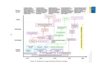
5 Recommendations for future research and Roadmap
A target roadmap for nano rectification is shown in Figure 16. There are 4 themes which have been
identified, in addition to the agreement of measurement standards. The timeline and links between
these themes is shown in Figure 16 and explained below:
1. Standards: Development of International standards for definition and measurements of efficacy
of energy harvesting devices - pan European to international with industrial support. 2015
delivery. [Several de facto standards exist and users quote from different standards, thus
materials, systems and devices can not be readily compared. Set up community debate on the
adoption of an appropriate standard parameter to enable easy comparison of technologies.]
2. Intelligent adaptive systems: Development of self tuning electronic systems control to account
for broadband excitation sources. Rectifier technology: go beyond the ’passive’ rectifier to
an active rectifier (system) for on the fly operational optimisation of EH devices - first small
scale demonstrators by 2016. [Challenge in scaling. Active rectification for transfer of real
and reactive power between transducer and storage element.]
3. Nanoscale Devices: Development of ‘zero’-control overhead synchronous rectifier for operation
with sub-threshold AC input signals - techniques and systems integration of state of the art
’rectification’ technologies (regular synchronous rectifiers and those with additional functions,
such as pre-biasing etc) to accelerate the nano materials based EH structures (such as ZnO
nano rods). First demonstration at the nanoscale: 2016.
4. Systems Integration and new materials: Miniaturisation and quality increase of passive elec-
trical component technologies (inductors and transformers) through the the use of improved
material systems, or alternative approaches, such as solid state techniques to the coupling
of electrical to magnetic energy. [Improvement in passive electronic component technology].
First demonstration of solid state solutions: 2018.
5. Hybrid Devices: Trade off between transducer complexity and electronics complexity and
their integration - electronics systems control and power processing hardware as an inte-
grated structure with the active material (piezo, electrostatic, magnetic). Systems integration
demonstrated: 2014
20](https://image.slidesharecdn.com/11190724-fb8a-4a60-8826-0088eb365806-151110114252-lva1-app6891/85/Energy-Harvesting-Report-22-320.jpg)
![Technology Strategy Board
Driving Innovation
6 Acknowledgements
The Materials Knowledge Transfer Network (KTN), Director - Dr Robert Quarshie and Technology
Manager - Smart and Emerging Technologies of the Materials KTN, Dr Steve Morris, for supporting
this study.
Smart Materials and Systems Committee (SMASC), Institute of Materials, Minerals and Mining,
London, UK.
Dr Mark Stewart, and Dr Paul Weaver, National Physical Laboratory, Teddington, UK.
EPSRC.
References
[1] S. R. Anton and H. A. Sodano, “A review of power harvesting using piezoelectric materials
(2003–2006),” Smart Materials and Structures, vol. 16, no. 3, pp. R1–R21, May 2007.
[2] S. P. Beeby, M. J. Tudor, and N. M. White, “Energy harvesting vibration sources for microsys-
tems applications,” Measurement Science and Technology, vol. 17, no. 12, pp. R175–R195,
Oct. 2006.
[3] N. S. Hudak and G. G. Amatucci, “Small-scale energy harvesting through thermoelectric,
vibration, and radiofrequency power conversion,” Journal of Applied Physics, vol. 103, no. 10,
p. 101301, 2008.
[4] P. D. Mitcheson, T. C. Green, and E. M. Yeatman, “Power processing circuits for electromag-
netic, electrostatic and piezoelectric inertial energy scavengers,” Microsystem Technologies,
vol. 13, no. 11-12, pp. 1629–1635, Jan. 2007.
[5] J. Liang and W.-H. Liao, “Energy flow in piezoelectric energy harvesting systems,” Smart
Materials and Structures, vol. 20, no. 1, p. 015005, Dec. 2010.
[6] A. Khaligh, P. Zeng, and C. Zheng, “Kinetic energy harvesting using piezoelectric and electro-
magnetic technologies—State of the art,” IEEE Transactions on Industrial Electronics, vol. 57,
no. 3, pp. 850–860, 2010.
[7] M. Lallart and D. Guyomar, “An optimized self-powered switching circuit for non-linear energy
harvesting with low voltage output,” Smart Materials and Structures, vol. 17, no. 3, p. 035030,
May 2008.
[8] J. Dicken, P. D. Mitcheson, I. Stoianov, and E. M. Yeatman, “Increased power output from
piezoelectric energy harvesters by pre-biasing,” PowerMEMS, Washington DC, pp. 1–4, 2010.
22](https://image.slidesharecdn.com/11190724-fb8a-4a60-8826-0088eb365806-151110114252-lva1-app6891/85/Energy-Harvesting-Report-24-320.jpg)
![Technology Strategy Board
Driving Innovation
[9] J. Dicken, I. Stoianov, P. D. Mitcheson, and E. M. Yeatman, “Power-extraction circuits for
piezoelectric energy harvesters in miniature and low-power applications,” IEEE Transactions on
Power Electronics, vol. 27, pp. 4514–4529, November 2012.
[10] L. R. Clare and S. G. Burrow, “Power conditioning for energy harvesting,” in Proc. SPIE, San
Diego, California, USA, March 2008.
[11] L. Karthikeyan and B. Amrutur, “Signal-powered low-drop-diode equivalent circuit for full-wave
bridge rectifier,” Power Electronics, IEEE Transactions on, vol. 27, no. 10, pp. 4192 –4201,
oct. 2012.
[12] L. Garbuio, M. Lallart, D. Guyomar, C. Richard, and D. Audigier, “Mechanical energy harvester
with ultralow threshold rectification based on SSHI nonlinear technique,” IEEE Transactions
on Industrial Electronics, vol. 56, no. 4, pp. 1048–1056, 2009.
[13] S. Meninger, J. O. Mur-Miranda, R. Amirtharajah, A. Chandrakasan, and J. Lang, “Vibration-
to-Electric Energy Conversion,” in Low Power Electronics and Design, 1999, International
Symposium on, August 1999, pp. 48–53.
[14] J. Wenck, R. Amirtharajah, J. Collier, and J. Siebert, “AC power supply circuits for energy
harvesting,” VLSI Circuits, 2007 IEEE Symposium on, pp. 92–93, 2007.
[15] P. D. Mitcheson, T. Sterken, C. He, M. Kiziroglou, E. M. Yeatman, and R. Puers, “Electrostatic
Microgenerators,” Measurement and Control, vol. 41, pp. 114–119, 2008.
[16] P. D. Mitcheson and T. C. Green, “Maximum effectiveness of electrostatic energy harvesters
when coupled to interface circuits,” IEEE Transactions on Circuits and Systems Part 1: Regular
Papers.
[17] D. Miki, Y. Suzuki, and N. Kasagi, “Effect of nonlinear external circuit on electrostatic damp-
ing force of micro electret generator,” in Solid-State Sensors, Actuators and Microsystems
Conference, 2009. TRANSDUCERS 2009. International, june 2009, pp. 636 – 639.
[18] P. D. Mitcheson, T. C. Green, E. M. Yeatman, and A. S. Holmes, “Architectures for Vibration-
Driven Micropower Generators,” IEEE/ASME Journal of Microelectromechanical Systems,
vol. 13, no. 3, pp. 429–440, June 2004.
[19] P. D. Mitcheson, E. M. Yeatman, G. K. Rao, A. S. Holmes, and T. C. Green, “Energy Harvesting
for Human and Machine Motion for Wireless Electronic Devices,” Proceedings of the IEEE,
vol. 96, no. 9, pp. 1457–1486, September 2008.
[20] K. A. Cook-Chennault, N. Thambi, and A. M. Sastry, “Powering MEMS portable devices—a
review of non-regenerative and regenerative power supply systems with special emphasis on
piezoelectric energy harvesting systems,” Smart Materials and Structures, vol. 17, no. 4, p.
043001, Jun. 2008.
23](https://image.slidesharecdn.com/11190724-fb8a-4a60-8826-0088eb365806-151110114252-lva1-app6891/85/Energy-Harvesting-Report-25-320.jpg)
![Technology Strategy Board
Driving Innovation
[21] H.-U. Kim, W.-H. Lee, H. V. R. Dias, and S. Priya, “Piezoelectric Microgenerators-Current Sta-
tus and Challenges,” IEEE Transactions on Ultrasonics, Ferroelectrics and Frequency Control,
vol. 56, no. 8, pp. 1555–1568.
[22] Z. Wang and Y. Xu, “Vibration energy harvesting device based on air-spaced piezoelectric
cantilevers,” Applied Physics Letters, vol. 90, no. 26, p. 263512, 2007.
[23] M. Stewart, P. M. Weaver, and M. G. Cain, “Charge redistribution in piezoelectric energy
harvesters,” Applied Physics Letters, vol. 100, no. 7, p. 073901, 2012.
[24] M. I. Friswell and S. Adhikari, “Sensor shape design for piezoelectric cantilever beams to harvest
vibration energy,” Journal of Applied Physics, vol. 108, no. 1, p. 014901, 2010.
[25] X. Gao, W.-H. Shih, and W. Y. Shih, “Induced voltage of piezoelectric unimorph cantilevers of
different nonpiezoelectric/piezoelectric length ratios,” Smart Materials and Structures, vol. 18,
no. 12, p. 125018, Oct. 2009.
[26] L. M. Miller, P. D. Mitcheson, E. Halvorsen, and P. K. Wright, “Coulomb-damped resonant
generators using piezoelectric transduction,” Applied Physics Letters, vol. 100, no. 23, p.
233901, 2012. [Online]. Available: http://link.aip.org/link/?APL/100/233901/1
[27] A. D. T. Elliott and P. D. Mitcheson, “Implementation of a single supply pre-biasing circuit for
piezoelectric energy harvesters,” in Eurosensors 2012, Krakow, Poland.
[28] R. Torah, P. Glynne-Jones, M. Tudor, T. O’Donnell, S. Roy, and S. Beeby, “Self-powered
autonomous wireless sensor node using vibration energy harvesting,” Measurement Science
and Technology, vol. 19, no. 12, p. 125202, 2008.
[29] L. R. Clare and S. G. Burrow, “Half-wave rectifiers offer advantages for vibration energy har-
vesters,” Electronics Letters, vol. 46, no. 24, pp. 1623 –1624, 25 2010.
[30] G. D. Szarka, P. P. Proynov, B. H. Stark, S. G. Burrow, and N. McNeill, “Experimental
investigation of inductorless, single-stage boost rectification for sub-mw electromagnetic energy
harvesters,” in Low Power Electronics and Design (ISLPED) 2011 International Symposium on,
aug. 2011, pp. 361 –366.
[31] P. D. Mitcheson, T. T. Toh, K. H. Wong, S. G. Burrow, and A. S. Holmes, “Tuning the reso-
nant frequency and damping of an electromagnetic energy harvester using power electronics,”
Circuits and Systems II: Express Briefs, IEEE Transactions on, vol. 58, no. 12, pp. 792 –796,
dec. 2011.
[32] M. Pinuela, P. D. Mitcheson, and S. Lucyszyn, “Analysis of scalable rectenna configurations for
harvesting high frequency ambient radiation,” in Proceedings of PowerMEMS 2010, Leuven,
Belgium, December 2010, pp. 41–44.
24](https://image.slidesharecdn.com/11190724-fb8a-4a60-8826-0088eb365806-151110114252-lva1-app6891/85/Energy-Harvesting-Report-26-320.jpg)