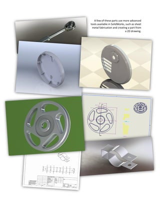
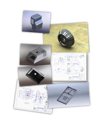
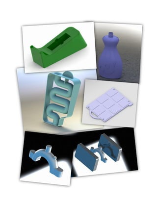
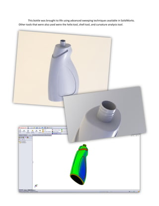
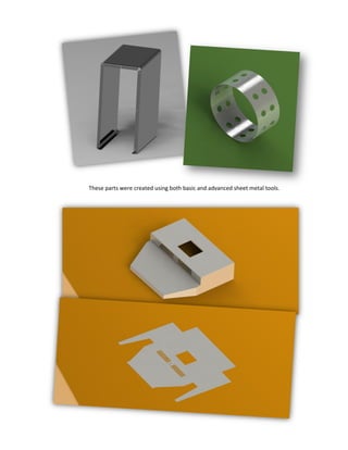
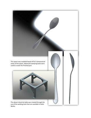
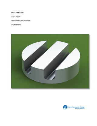
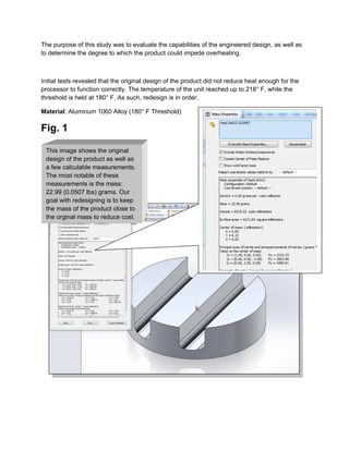
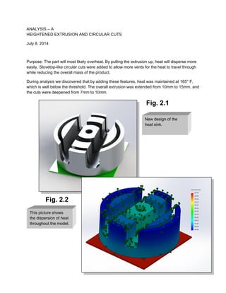
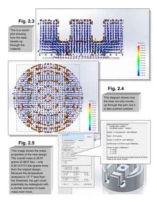
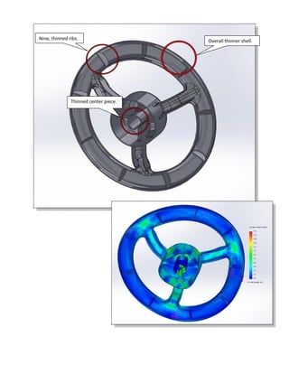
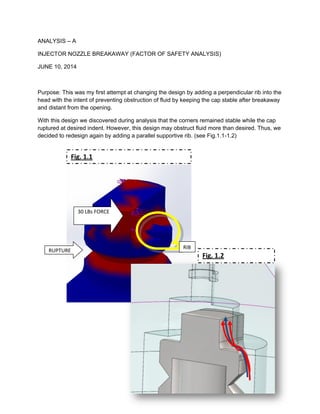
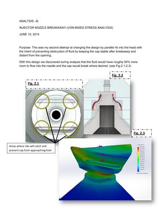
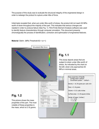
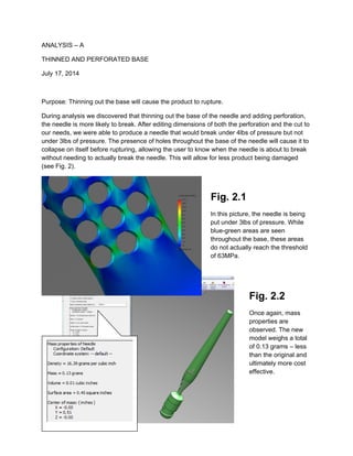
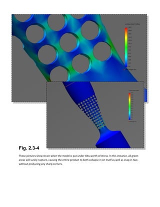
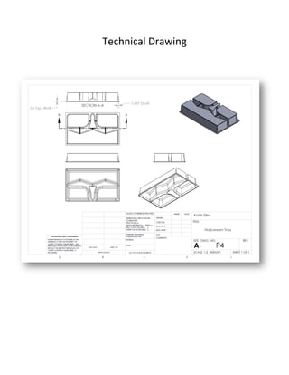
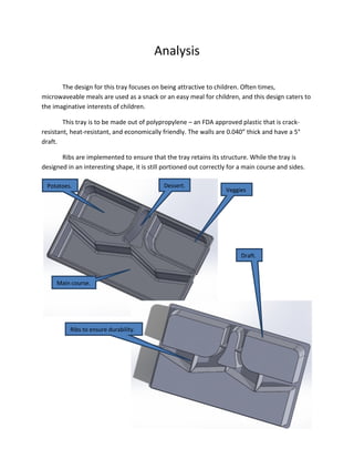
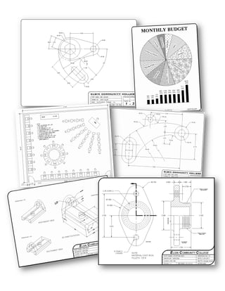
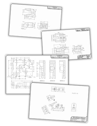
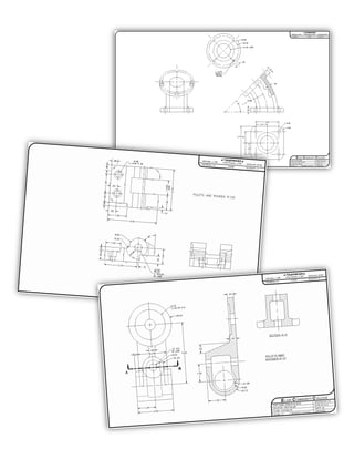
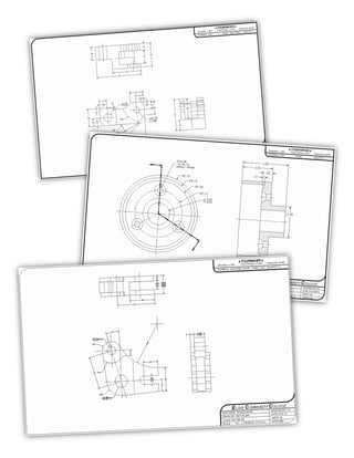
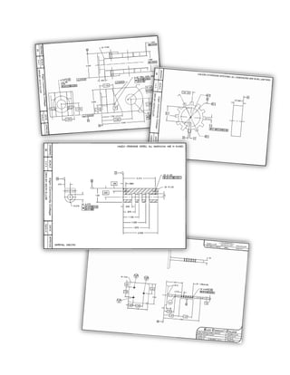
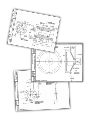
SOLIDWORKS
These parts were generated using SolidWorks, and in creating each of them, a new skill was
used or observed. They are each unique in their creation, though they all required a large amount of
focus and patience. Among basic skills used in SolidWorks, a few advanced ones were used as well.
Although these parts may appear simple, they all apply the fundamental skills used in all engineering.
A few of these parts use more advanced
tools available in SolidWorks, such as sheet
metal fabrication and creating a part from
a 2D drawing.
While the design on this part is relatively simple,
the processes used to create it were not.
Through using SolidWorks’ equation
tool, this part can easily
switch between four
different designs.
This bottle was brought to life using advanced sweeping techniques available in SolidWorks.
Other tools that were also used were the helix tool, shell tool, and curvature analysis tool.
These parts were created using both basic and advanced sheet metal tools.
This spoon was modeled based off of 2-dimensional
views of the spoon. Advanced sweeping tools were
used to create the finished part.
The above industrial table was created through the
use of the welding tools that are available in Solid-
Works.
FINITE ELEMENTAL
ANALYSIS
The following reports were put together through finite elemental analysis. All of the tests were
completed using tools available in SolidWorks. These reports include the analysis of stress and strain on
individual models, the dispersion of heat, and the flow of water and air. Once analyzed, the parts were
redesigned to be more efficient and cost-effective.
HEAT SINK STUDY
July 8, 2014
VELEXIUM CORPORATION
BY: Keith Eller
The purpose of this study was to evaluate the capabilities of the engineered design, as well as
to determine the degree to which the product could impede overheating.
Initial tests revealed that the original design of the product did not reduce heat enough for the
processor to function correctly. The temperature of the unit reached up to 218° F, while the
threshold is held at 180° F. As such, redesign is in order.
Material: Aluminum 1060 Alloy (180° F Threshold)
Fig. 1
This image shows the original
design of the product as well as
a few calculable measurements.
The most notable of these
measurements is the mass:
22.99 (0.0507 lbs) grams. Our
goal with redesigning is to keep
the mass of the product close to
the orginal mass to reduce cost.
ANALYSIS – A
HEIGHTENED EXTRUSION AND CIRCULAR CUTS
July 8, 2014
Purpose: The part will most likely overheat. By pulling the extrusion up, heat will disperse more
easily. Stovetop-like circular cuts were added to allow more vents for the heat to travel through
while reducing the overall mass of the product.
During analysis we discovered that by adding these features, heat was maintained at 165° F,
which is well below the threshold. The overall extrusion was extended from 10mm to 15mm, and
the cuts were deepened from 7mm to 10mm.
Fig. 2.1
Fig. 2.2
This picture shows
the dispersion of heat
throughout the model.
New design of the
heat sink.
Fig. 2.3
Fig. 2.4
Fig. 2.5
This is a vector
plot showing
how the heat
travels up
through the
material.
This diagram shows how
the heat not only moves
up through the part, but it
is also pushed outward.
This image shows the mass
properties of the new design.
The overall mass is 28.91
grams (0.0637 lbs) – only
5.92 (0.0131 lbs) grams more
than the original design.
Because the temperature
analyzed is 15° F less than
the threshold, the part could
potentially be redesigned with
a shorter extrusion to lower
mass even more.
CONCLUSION
Testing and analysis revealed that the product could not reduce the heat enough for the
processor to work properly. We undertook the responsibility of redesigning the heat to absorb more
heat.
After increasing the height of the overall extrusion and including circular cuts, the product was
able to reduce the overall heat to 165° F, which is 15° F lower than the 180° F threshold. The mass was
increased by a mere 5.92 (0.0131 lbs) grams, which maintains a similar cost to the original design.
All analyses and tests are computer simulated and do not provide enough data to establish fact.
TOY STEERING WHEEL STUDY
July 1, 2014
ROGERS TOY COMPANY
BY: Keith Eller
This study areas of displacement
throughout the model.
Displacement never exceeds the
acrylic yield strength, so there is
no need for concern in the
aspect of shearing.
This analysis shows von Mises
stress throughout the model.
While acrylic can handle 45 MPa
worth of stress, this stress in this
model never exceeds 8.1m which
indicates no signs of rupture.
The purpose of this study was to evaluate the structural integrity of the engineered design, as
well as to determine the elements of a controlled failure in order to produce alternative cost-
effective solutions.
Initial tests revealed that there are no areas that rupture under 30lbs worth of torque (See Fig.
1). Due to this finding, we have assumed that the part is over engineered; as such, we plan to
provide alternative solutions which will maintain stability of the part as well as reduce cost. FEA-
Finite Element Analysis software was used to identify undesirable feature characteristics
through computer simulation. This document presents chronologically the process of
identification, correction and optimization of engineered features.
Material: Acrylic (MPa Threshold 45 < or =)
Fig. 1.1
Fig. 1.2
Simulated 30lbs torque
This table depicts the mass
properties of the model. The
current mass is 0.20 pounds –
our goal is to cut that in half.
Fig. 1.3
These images demonstrate that
even after removing ribs and
thinning out the model, the stress
on the part does not approach
the predetermined yield strength.
ANALYSIS – A
REDUCED, THINNED RIBS AND THINNED SHELL
July 1, 2014
Purpose: The part may be over engineered. By reducing the number of ribs used and by
reducing the amount of material used, we hope to maintain structural stability while reducing
cost.
During analysis we discovered that by reducing the amount of ribs used and thinning the
remaining ribs, the model would remain intact under 30lbs worth of torque. We also thinned out
the overall shell. After altering these features, the mass was reduced from 0.20 to 0.09,
reducing cost of the product by more than half (see Fig. 2).
Fig. 2.1
Nine, thinned ribs. Overall thinner shell.
Thinned center piece.
CONCLUSION
Testing and analysis revealed that there were no areas where damage was prone. As such, we
assumed that the part was over engineered and proceeded to find a solution that would reduce the cost
of the part while maintaining structural stability.
After reducing the amount of ribs used and thinning out the overall shell of the part, it was
brought to our attention that the part did not appear to rupture. We were able to reduce the mass of
the part from .20lbs to .09lbs, which would greatly reduce cost.
All analyses and tests are computer simulated and do not provide enough data to establish fact.
REAR PHONE BEZEL STUDY
June 26, 2014
HEALY CORPORATION
BY: Keith Eller
The purpose of this study was to evaluate the structural integrity of the engineered design, as
well as to determine the elements of a controlled failure in order to produce alternative solutions.
Initial tests revealed that there are two areas which required further inspection. These regions
included the top of the bezel and the screw holes (See Fig. 1). FEA-Finite Element Analysis
software was used to identify undesirable feature characteristics through computer simulation.
This document presents chronologically the process of identification, correction and optimization
of engineered features.
Material: Acrylic (MPa Threshold 45 < or =)
Fig. 1.1
FOS = 3
This study depicts questionable
areas when the phone is subjected
to 100 lbs of force and analyzed at
a safety factor of 3. There is much
strain on the top of the bezel and
the screw holes.
Fig. 1.2
0-45 MPA
This von Mises stress analysis
reveals areas where the model
approaches its threshold of 45
MPa. While the model remains
below the threshold, it is still
wise to encourage redesigning.
Simulated 100
lbs. force
ANALYSIS – A
ADDITIONAL RIBS
June 26, 2014
Purpose: The Rear Bezel may require additional reinforcement to prevent failure or cracking.
During analysis we discovered that by adding additional ribs in the indicated areas, damageable
areas are reduced greatly in size. According to the von Mises stress analysis, the model still
approaches 45 MPa, though this area is focused on the screw hole ribs instead of the holes
themselves. We suggest thickening the new ribs to ensure greater quality (see Fig. 2).
Fig. 2
0-42 MPA
By adding additional ribs,
the analysis shows less signs
of damage
CONCLUSION
Testing and analysis revealed that there were two particular areas where damage was prone.
These regions included the top of the rear bezel as well as the screw holes. We reasoned that adding
more ribs to both of these areas would reduce potential damage from a 100 lb force.
Testing showed that potential damage was decreased immensely after adding the ribs. We
suggest increasing the rib size of the new screw hole ribs, but regardless of this change, potential
damage has already been reduced.
All analyses and tests are computer simulated and do not provide enough data to establish fact.
INJECTOR CAP STUDY
JUNE 10, 2014
UNITED STATES MILITARY
DEPARTMENT OF DEFENSE
BY: KEITH ELLER
The purpose of this study was to evaluate the structural integrity of the engineered design, as
well as to determine the elements of a controlled failure while preventing clogging of the nozzle.
Preliminary studies indicated clogging of the injector nozzle was observed thus forcing a
redesign of the Injector Break-away head. FEA-Finite Element Analysis software was used to
identify undesirable feature characteristics through computer simulation. This document
presents chronologically the process of identification, correction and optimization of engineered
features.
Material: Acrylic (Medical Grade Cast) (MPa Threshold 45 ≤)
ANALYSIS
BREAK-AWAY HEAD
RISK OF FAILURE
ANALYSIS – A
INJECTOR NOZZLE BREAKAWAY (FACTOR OF SAFETY ANALYSIS)
JUNE 10, 2014
Purpose: This was my first attempt at changing the design by adding a perpendicular rib into the
head with the intent of preventing obstruction of fluid by keeping the cap stable after breakaway
and distant from the opening.
With this design we discovered during analysis that the corners remained stable while the cap
ruptured at desired indent. However, this design may obstruct fluid more than desired. Thus, we
decided to redesign again by adding a parallel supportive rib. (see Fig.1.1-1.2)
30 LBs FORCE
RUPTURE
RIB
Fig. 1.1
Fig. 1.2
ANALYSIS –B
INJECTOR NOZZLE BREAKAWAY (VON MISES STRESS ANALYSIS)
JUNE 10, 2014
Purpose: This was my second attempt at changing the design by parallel rib into the head with
the intent of preventing obstruction of fluid by keeping the cap stable after breakaway and
distant from the opening.
With this design we discovered during analysis that the fluid would have roughly 50% more
room to flow into the needle and the cap would break where desired. (see Fig.2.1-2.3)
Areas where ribs will catch and
prevent cap from approaching hole
Fig. 2.1
Fig. 2.2
Fig. 2.3
CONCLUSION
Both designs yielded in non-failing results according to the analyses. It is also apparent with
each design that the cap would snap off desirably without having the ability to clog the needle. Both
designs would roughly require the same amount of machining, which would involve simple milling. This
is intended to reduce cost of tooling. While the perpendicular rib and the parallel rib both achieve the
same goal, the parallel rib allows more fluid to enter the needle. This suggests that the design #2 is
superior to design #1.
STREP NEEDLE STUDY
July 17, 2014
VELEXIUM LABS
BY: Keith Eller
The purpose of this study was to evaluate the structural integrity of the engineered design in
order to redesign the product to rupture under 4lbs of force.
Initial tests revealed that, when put under 4lbs worth of stress, the product did not reach 63 MPa
worth of strain throughout the majority of the part. This indicates that serious changes are
needed in order to produce failure (See Fig. 1). FEA-Finite Element Analysis software was used
to identify feature characteristics through computer simulation. This document presents
chronologically the process of identification, correction and optimization of engineered features.
Material: Delrin (MPa Threshold 63 < or =)
Fig. 1.1
This study depicts areas that are
subject to strain under 4lbs worth of
stress. As indicated by the chart on
the left, strain only approaches 63
MPa in minimal areas.
Fig. 1.2
This picture shows the mass
properties of the part. The most
notable of these properties is
the mass, which is 0.16 grams.
Simulated 4lbs force
ANALYSIS – A
THINNED AND PERFORATED BASE
July 17, 2014
Purpose: Thinning out the base will cause the product to rupture.
During analysis we discovered that thinning out the base of the needle and adding perforation,
the needle is more likely to break. After editing dimensions of both the perforation and the cut to
our needs, we were able to produce a needle that would break under 4lbs of pressure but not
under 3lbs of pressure. The presence of holes throughout the base of the needle will cause it to
collapse on itself before rupturing, allowing the user to know when the needle is about to break
without needing to actually break the needle. This will allow for less product being damaged
(see Fig. 2).
Fig. 2.1
In this picture, the needle is being
put under 3lbs of pressure. While
blue-green areas are seen
throughout the base, these areas
do not actually reach the threshold
of 63MPa.
Fig. 2.2
Once again, mass
properties are
observed. The new
model weighs a total
of 0.13 grams – less
than the original and
ultimately more cost
effective.
Fig. 2.3-4
These pictures show strain when the model is put under 4lbs worth of stress. In this instance, all green
areas will surely rupture, causing the entire product to both collapse in on itself as well as snap in two
without producing any sharp corners.
CONCLUSION
Testing and analysis revealed that product would not rupture in any way when subjected to 4lbs
of force. Redesign was put into action, which produces a model with a thinned out and perforated base.
Testing showed that the product would collapse and break under 4lbs of force while remaining
intact under 3lbs of force. When the model was put under 3lbs of pressure, stress was observed. This
leads us to believe that the product will tend to collapse before breaking, allowing the user to know
when the product is about to break and essentially reduce overall damage. The mass was reduced in the
new model, allowing the product to be made using less material which in turn allows the product to be
made for less money.
All analyses and tests are computer simulated and do not provide enough data to establish fact.
CREO
PARAMETRIC
Each of these projects was designed, created, assembled, rendered, dimensioned, and drawn in
Creo Parametric 2.0. The process used to create these models utilized problem solving skills, logical and
critical thinking, and a fair amount of creativity. Some models even push the tools provided on Creo to
their limits, and perhaps a bit further. Above all else, everything was designed and constructed with
great care and attention to detail.
Both models were simply an exercise in bottom-up assembly. When assembled properly,
dragging the crank around on the top model will cause the entire assembly to function realistically.
This model was created with sheet metal. It shows an understanding of how sheet metal can be
used to more effectively create models in Creo.
This boat was created for a contest, and it definitely uses Creo to its full potential. A great deal
of creativity and careful design went into the created of this boat. It was all conceived, designed,
modeled, assembled, and rendered with my own two hands (so to speak).
This exercise utilized Creo’s ability to assemble models together, and then change a single
dimension to alter the entire outcome of how the assembly appears.
This mp3 player was produced using top-down assembly. Some pieces were provided, but others were
missing and needed to be fashioned to fit with the entire assembly.
RHINO 3D
The following section includes products that were modeled and rendered using Rhino 3D. These
products include simple designs that were drafted from prints as well as designs that were created from
scratch to enhance pre-existing products. The emphasis of these products is the design and
presentation, as each one underwent revision processes that are often used in commercial industry.
These products show an attention to detail as well as a profound use of creativity. These photos should
be viewed as if one were flipping through a product catalogue.
Project 1
Stapler
Initial Sketches
Analysis
This design was chosen for both its appearance and functionality. The design is intended
to be smooth and sleek – enjoyable to touch. The curvature along the press is intended to be fit
to one’s hand.
The functionality of this stapler is highlighted by its ability to extend and retract,
allowing the user to staple much larger pieces of work together. It is often frustrating when a
stapler cannot reach where one wants it to, but that is a thing of the past with this concept
Rubber feet to
prevent sliding.
Tracks to allow
extension.
Upper jaw is capable
of extending.
Project 2
Cell Phone
Initial Sketches
Analysis
The simplicity of a smart phone was implemented into this design. In having few
features, the product portrays an image of unity. The features that do exist focus on durability
and usefulness.
Whereas most other cell phone have a simple one-speaker sound system, the design for
this cell phone uses two different speakers angled toward the listener’s ear. This can help
enhance sound quality, volume issues, and can provide stereo sound for listening to music.
Aside from having a touchpad, this phone also includes a “roller” to help speed up
moving through menus and clicking on options with precision.
To avoid permanent damage that may be caused to the device from dropping, the
corners have been equipped with flat, rubber shock absorbers. The flat corners will disperse the
force of any impact, prolonging the life of the device.
The final feature included with this device is a solar panel, intended to provide energy
when the user needs to make an emergency call.
Roller used for quick,
convenient navigation.
Stereo speakers
improve sound
quality.
Microphone.
Shock-absorbing
corners.
Solar panel for
emergency power.
Project 3
Watch
Initial Sketches
Analysis
Because the market for watches is declining, this concept was tricky to come up with.
People now simply use their phones to check the time, so the question arises: Why do people
still use watches?
The answer comes in two forms – 1: Style. 2: Usefulness, especially in the absence of
other electronics.
The concept focuses on both of these factors, but more so in the usefulness
department. With the idea of a hiker or camper in mind, this watch uses different tools to prove
its worth.
The first tool is a flashlight located at a 45° angle from the user’s wrist. This light can be
used when all other light fails, and it can also serve as a distress beacon if the user is lost.
Another similar feature included with this product is a speaker intended to send out
short, loud beeps to alert others of the user’s location. This can be helpful in dire and casual
situations.
A compass is included on the face of this watch, to allow the user to always know which
direction they are headed. Again, if the user becomes lost, this will come in handy.
This watch also includes a solar panel to allow the device to continue being useful,
despite having its battery depleted.
Compass to aid
in navigation.
Solar panel to
provide emergency
energy.
Speaker designed
to send out
distress signals.
Leather band to
ensure durability.
Flashlight to
provide light and
a distress beacon.
Glow-in-the-
dark face.
Project 4
Thermoplastic Tray
Initial Sketches
Technical Drawing
Analysis
The design for this tray focuses on being attractive to children. Often times,
microwaveable meals are used as a snack or an easy meal for children, and this design caters to
the imaginative interests of children.
This tray is to be made out of polypropylene – an FDA approved plastic that is crack-
resistant, heat-resistant, and economically friendly. The walls are 0.040” thick and have a 5°
draft.
Ribs are implemented to ensure that the tray retains its structure. While the tray is
designed in an interesting shape, it is still portioned out correctly for a main course and sides.
Veggies
.
Dessert.Potatoes.
Main course.
Ribs to ensure durability.
Draft.
AutoCAD
The drawings contained within the next few pages were all drawn on AutoCAD. They are
replications, but the means by which to create them were all determined by the drawer. They show how
well one can get from point A to point B, and the experience gained from these drawings has allowed
me to put together drawings quicker and more efficiently. A gifted engineer has intuition, attention for
detail, creativity, and great comprehension of the software and tools they are using as well as the model
which they are creating. These drawings show all of these traits to one degree or another.
These first few images were put together using AutoCAD’s 3D features, including extruding,
cutting, material mapping, image mapping, lighting, and rendering.
ARCHITECTURE
These architectural drawings were put together using AutoCAD. They demonstrate an
understanding of the basic and advanced aspects of architecture. All of these drawings were created for
a single house, which was designed completely and entirely from scratch. Every feature in the house has
a specific purpose, and the overall emphasis of the structure is efficiency. In order to design this house, I
was required to have an understanding of many different options and processes used in the structural
industry – from foundation planning to electrical planning to plumbing (and much more).
Employment Portfolio (1)

Employment Portfolio (1)

  • 1.
    SOLIDWORKS These parts weregenerated using SolidWorks, and in creating each of them, a new skill was used or observed. They are each unique in their creation, though they all required a large amount of focus and patience. Among basic skills used in SolidWorks, a few advanced ones were used as well. Although these parts may appear simple, they all apply the fundamental skills used in all engineering.
  • 2.
    A few ofthese parts use more advanced tools available in SolidWorks, such as sheet metal fabrication and creating a part from a 2D drawing.
  • 5.
    While the designon this part is relatively simple, the processes used to create it were not. Through using SolidWorks’ equation tool, this part can easily switch between four different designs.
  • 6.
    This bottle wasbrought to life using advanced sweeping techniques available in SolidWorks. Other tools that were also used were the helix tool, shell tool, and curvature analysis tool.
  • 7.
    These parts werecreated using both basic and advanced sheet metal tools.
  • 8.
    This spoon wasmodeled based off of 2-dimensional views of the spoon. Advanced sweeping tools were used to create the finished part. The above industrial table was created through the use of the welding tools that are available in Solid- Works.
  • 9.
    FINITE ELEMENTAL ANALYSIS The followingreports were put together through finite elemental analysis. All of the tests were completed using tools available in SolidWorks. These reports include the analysis of stress and strain on individual models, the dispersion of heat, and the flow of water and air. Once analyzed, the parts were redesigned to be more efficient and cost-effective.
  • 10.
    HEAT SINK STUDY July8, 2014 VELEXIUM CORPORATION BY: Keith Eller
  • 11.
    The purpose ofthis study was to evaluate the capabilities of the engineered design, as well as to determine the degree to which the product could impede overheating. Initial tests revealed that the original design of the product did not reduce heat enough for the processor to function correctly. The temperature of the unit reached up to 218° F, while the threshold is held at 180° F. As such, redesign is in order. Material: Aluminum 1060 Alloy (180° F Threshold) Fig. 1 This image shows the original design of the product as well as a few calculable measurements. The most notable of these measurements is the mass: 22.99 (0.0507 lbs) grams. Our goal with redesigning is to keep the mass of the product close to the orginal mass to reduce cost.
  • 12.
    ANALYSIS – A HEIGHTENEDEXTRUSION AND CIRCULAR CUTS July 8, 2014 Purpose: The part will most likely overheat. By pulling the extrusion up, heat will disperse more easily. Stovetop-like circular cuts were added to allow more vents for the heat to travel through while reducing the overall mass of the product. During analysis we discovered that by adding these features, heat was maintained at 165° F, which is well below the threshold. The overall extrusion was extended from 10mm to 15mm, and the cuts were deepened from 7mm to 10mm. Fig. 2.1 Fig. 2.2 This picture shows the dispersion of heat throughout the model. New design of the heat sink.
  • 13.
    Fig. 2.3 Fig. 2.4 Fig.2.5 This is a vector plot showing how the heat travels up through the material. This diagram shows how the heat not only moves up through the part, but it is also pushed outward. This image shows the mass properties of the new design. The overall mass is 28.91 grams (0.0637 lbs) – only 5.92 (0.0131 lbs) grams more than the original design. Because the temperature analyzed is 15° F less than the threshold, the part could potentially be redesigned with a shorter extrusion to lower mass even more.
  • 14.
    CONCLUSION Testing and analysisrevealed that the product could not reduce the heat enough for the processor to work properly. We undertook the responsibility of redesigning the heat to absorb more heat. After increasing the height of the overall extrusion and including circular cuts, the product was able to reduce the overall heat to 165° F, which is 15° F lower than the 180° F threshold. The mass was increased by a mere 5.92 (0.0131 lbs) grams, which maintains a similar cost to the original design. All analyses and tests are computer simulated and do not provide enough data to establish fact.
  • 15.
    TOY STEERING WHEELSTUDY July 1, 2014 ROGERS TOY COMPANY BY: Keith Eller
  • 16.
    This study areasof displacement throughout the model. Displacement never exceeds the acrylic yield strength, so there is no need for concern in the aspect of shearing. This analysis shows von Mises stress throughout the model. While acrylic can handle 45 MPa worth of stress, this stress in this model never exceeds 8.1m which indicates no signs of rupture. The purpose of this study was to evaluate the structural integrity of the engineered design, as well as to determine the elements of a controlled failure in order to produce alternative cost- effective solutions. Initial tests revealed that there are no areas that rupture under 30lbs worth of torque (See Fig. 1). Due to this finding, we have assumed that the part is over engineered; as such, we plan to provide alternative solutions which will maintain stability of the part as well as reduce cost. FEA- Finite Element Analysis software was used to identify undesirable feature characteristics through computer simulation. This document presents chronologically the process of identification, correction and optimization of engineered features. Material: Acrylic (MPa Threshold 45 < or =) Fig. 1.1 Fig. 1.2 Simulated 30lbs torque
  • 17.
    This table depictsthe mass properties of the model. The current mass is 0.20 pounds – our goal is to cut that in half. Fig. 1.3
  • 18.
    These images demonstratethat even after removing ribs and thinning out the model, the stress on the part does not approach the predetermined yield strength. ANALYSIS – A REDUCED, THINNED RIBS AND THINNED SHELL July 1, 2014 Purpose: The part may be over engineered. By reducing the number of ribs used and by reducing the amount of material used, we hope to maintain structural stability while reducing cost. During analysis we discovered that by reducing the amount of ribs used and thinning the remaining ribs, the model would remain intact under 30lbs worth of torque. We also thinned out the overall shell. After altering these features, the mass was reduced from 0.20 to 0.09, reducing cost of the product by more than half (see Fig. 2). Fig. 2.1
  • 19.
    Nine, thinned ribs.Overall thinner shell. Thinned center piece.
  • 20.
    CONCLUSION Testing and analysisrevealed that there were no areas where damage was prone. As such, we assumed that the part was over engineered and proceeded to find a solution that would reduce the cost of the part while maintaining structural stability. After reducing the amount of ribs used and thinning out the overall shell of the part, it was brought to our attention that the part did not appear to rupture. We were able to reduce the mass of the part from .20lbs to .09lbs, which would greatly reduce cost. All analyses and tests are computer simulated and do not provide enough data to establish fact.
  • 21.
    REAR PHONE BEZELSTUDY June 26, 2014 HEALY CORPORATION BY: Keith Eller
  • 22.
    The purpose ofthis study was to evaluate the structural integrity of the engineered design, as well as to determine the elements of a controlled failure in order to produce alternative solutions. Initial tests revealed that there are two areas which required further inspection. These regions included the top of the bezel and the screw holes (See Fig. 1). FEA-Finite Element Analysis software was used to identify undesirable feature characteristics through computer simulation. This document presents chronologically the process of identification, correction and optimization of engineered features. Material: Acrylic (MPa Threshold 45 < or =) Fig. 1.1 FOS = 3 This study depicts questionable areas when the phone is subjected to 100 lbs of force and analyzed at a safety factor of 3. There is much strain on the top of the bezel and the screw holes. Fig. 1.2 0-45 MPA This von Mises stress analysis reveals areas where the model approaches its threshold of 45 MPa. While the model remains below the threshold, it is still wise to encourage redesigning. Simulated 100 lbs. force
  • 23.
    ANALYSIS – A ADDITIONALRIBS June 26, 2014 Purpose: The Rear Bezel may require additional reinforcement to prevent failure or cracking. During analysis we discovered that by adding additional ribs in the indicated areas, damageable areas are reduced greatly in size. According to the von Mises stress analysis, the model still approaches 45 MPa, though this area is focused on the screw hole ribs instead of the holes themselves. We suggest thickening the new ribs to ensure greater quality (see Fig. 2). Fig. 2 0-42 MPA By adding additional ribs, the analysis shows less signs of damage
  • 24.
    CONCLUSION Testing and analysisrevealed that there were two particular areas where damage was prone. These regions included the top of the rear bezel as well as the screw holes. We reasoned that adding more ribs to both of these areas would reduce potential damage from a 100 lb force. Testing showed that potential damage was decreased immensely after adding the ribs. We suggest increasing the rib size of the new screw hole ribs, but regardless of this change, potential damage has already been reduced. All analyses and tests are computer simulated and do not provide enough data to establish fact.
  • 25.
    INJECTOR CAP STUDY JUNE10, 2014 UNITED STATES MILITARY DEPARTMENT OF DEFENSE BY: KEITH ELLER
  • 26.
    The purpose ofthis study was to evaluate the structural integrity of the engineered design, as well as to determine the elements of a controlled failure while preventing clogging of the nozzle. Preliminary studies indicated clogging of the injector nozzle was observed thus forcing a redesign of the Injector Break-away head. FEA-Finite Element Analysis software was used to identify undesirable feature characteristics through computer simulation. This document presents chronologically the process of identification, correction and optimization of engineered features. Material: Acrylic (Medical Grade Cast) (MPa Threshold 45 ≤) ANALYSIS BREAK-AWAY HEAD RISK OF FAILURE
  • 27.
    ANALYSIS – A INJECTORNOZZLE BREAKAWAY (FACTOR OF SAFETY ANALYSIS) JUNE 10, 2014 Purpose: This was my first attempt at changing the design by adding a perpendicular rib into the head with the intent of preventing obstruction of fluid by keeping the cap stable after breakaway and distant from the opening. With this design we discovered during analysis that the corners remained stable while the cap ruptured at desired indent. However, this design may obstruct fluid more than desired. Thus, we decided to redesign again by adding a parallel supportive rib. (see Fig.1.1-1.2) 30 LBs FORCE RUPTURE RIB Fig. 1.1 Fig. 1.2
  • 28.
    ANALYSIS –B INJECTOR NOZZLEBREAKAWAY (VON MISES STRESS ANALYSIS) JUNE 10, 2014 Purpose: This was my second attempt at changing the design by parallel rib into the head with the intent of preventing obstruction of fluid by keeping the cap stable after breakaway and distant from the opening. With this design we discovered during analysis that the fluid would have roughly 50% more room to flow into the needle and the cap would break where desired. (see Fig.2.1-2.3) Areas where ribs will catch and prevent cap from approaching hole Fig. 2.1 Fig. 2.2 Fig. 2.3
  • 29.
    CONCLUSION Both designs yieldedin non-failing results according to the analyses. It is also apparent with each design that the cap would snap off desirably without having the ability to clog the needle. Both designs would roughly require the same amount of machining, which would involve simple milling. This is intended to reduce cost of tooling. While the perpendicular rib and the parallel rib both achieve the same goal, the parallel rib allows more fluid to enter the needle. This suggests that the design #2 is superior to design #1.
  • 30.
    STREP NEEDLE STUDY July17, 2014 VELEXIUM LABS BY: Keith Eller
  • 31.
    The purpose ofthis study was to evaluate the structural integrity of the engineered design in order to redesign the product to rupture under 4lbs of force. Initial tests revealed that, when put under 4lbs worth of stress, the product did not reach 63 MPa worth of strain throughout the majority of the part. This indicates that serious changes are needed in order to produce failure (See Fig. 1). FEA-Finite Element Analysis software was used to identify feature characteristics through computer simulation. This document presents chronologically the process of identification, correction and optimization of engineered features. Material: Delrin (MPa Threshold 63 < or =) Fig. 1.1 This study depicts areas that are subject to strain under 4lbs worth of stress. As indicated by the chart on the left, strain only approaches 63 MPa in minimal areas. Fig. 1.2 This picture shows the mass properties of the part. The most notable of these properties is the mass, which is 0.16 grams. Simulated 4lbs force
  • 32.
    ANALYSIS – A THINNEDAND PERFORATED BASE July 17, 2014 Purpose: Thinning out the base will cause the product to rupture. During analysis we discovered that thinning out the base of the needle and adding perforation, the needle is more likely to break. After editing dimensions of both the perforation and the cut to our needs, we were able to produce a needle that would break under 4lbs of pressure but not under 3lbs of pressure. The presence of holes throughout the base of the needle will cause it to collapse on itself before rupturing, allowing the user to know when the needle is about to break without needing to actually break the needle. This will allow for less product being damaged (see Fig. 2). Fig. 2.1 In this picture, the needle is being put under 3lbs of pressure. While blue-green areas are seen throughout the base, these areas do not actually reach the threshold of 63MPa. Fig. 2.2 Once again, mass properties are observed. The new model weighs a total of 0.13 grams – less than the original and ultimately more cost effective.
  • 33.
    Fig. 2.3-4 These picturesshow strain when the model is put under 4lbs worth of stress. In this instance, all green areas will surely rupture, causing the entire product to both collapse in on itself as well as snap in two without producing any sharp corners.
  • 34.
    CONCLUSION Testing and analysisrevealed that product would not rupture in any way when subjected to 4lbs of force. Redesign was put into action, which produces a model with a thinned out and perforated base. Testing showed that the product would collapse and break under 4lbs of force while remaining intact under 3lbs of force. When the model was put under 3lbs of pressure, stress was observed. This leads us to believe that the product will tend to collapse before breaking, allowing the user to know when the product is about to break and essentially reduce overall damage. The mass was reduced in the new model, allowing the product to be made using less material which in turn allows the product to be made for less money. All analyses and tests are computer simulated and do not provide enough data to establish fact.
  • 35.
    CREO PARAMETRIC Each of theseprojects was designed, created, assembled, rendered, dimensioned, and drawn in Creo Parametric 2.0. The process used to create these models utilized problem solving skills, logical and critical thinking, and a fair amount of creativity. Some models even push the tools provided on Creo to their limits, and perhaps a bit further. Above all else, everything was designed and constructed with great care and attention to detail.
  • 37.
    Both models weresimply an exercise in bottom-up assembly. When assembled properly, dragging the crank around on the top model will cause the entire assembly to function realistically. This model was created with sheet metal. It shows an understanding of how sheet metal can be used to more effectively create models in Creo.
  • 39.
    This boat wascreated for a contest, and it definitely uses Creo to its full potential. A great deal of creativity and careful design went into the created of this boat. It was all conceived, designed, modeled, assembled, and rendered with my own two hands (so to speak).
  • 40.
    This exercise utilizedCreo’s ability to assemble models together, and then change a single dimension to alter the entire outcome of how the assembly appears. This mp3 player was produced using top-down assembly. Some pieces were provided, but others were missing and needed to be fashioned to fit with the entire assembly.
  • 41.
    RHINO 3D The followingsection includes products that were modeled and rendered using Rhino 3D. These products include simple designs that were drafted from prints as well as designs that were created from scratch to enhance pre-existing products. The emphasis of these products is the design and presentation, as each one underwent revision processes that are often used in commercial industry. These products show an attention to detail as well as a profound use of creativity. These photos should be viewed as if one were flipping through a product catalogue.
  • 42.
  • 43.
  • 44.
    Analysis This design waschosen for both its appearance and functionality. The design is intended to be smooth and sleek – enjoyable to touch. The curvature along the press is intended to be fit to one’s hand. The functionality of this stapler is highlighted by its ability to extend and retract, allowing the user to staple much larger pieces of work together. It is often frustrating when a stapler cannot reach where one wants it to, but that is a thing of the past with this concept Rubber feet to prevent sliding. Tracks to allow extension. Upper jaw is capable of extending.
  • 45.
  • 46.
  • 47.
    Analysis The simplicity ofa smart phone was implemented into this design. In having few features, the product portrays an image of unity. The features that do exist focus on durability and usefulness. Whereas most other cell phone have a simple one-speaker sound system, the design for this cell phone uses two different speakers angled toward the listener’s ear. This can help enhance sound quality, volume issues, and can provide stereo sound for listening to music. Aside from having a touchpad, this phone also includes a “roller” to help speed up moving through menus and clicking on options with precision. To avoid permanent damage that may be caused to the device from dropping, the corners have been equipped with flat, rubber shock absorbers. The flat corners will disperse the force of any impact, prolonging the life of the device. The final feature included with this device is a solar panel, intended to provide energy when the user needs to make an emergency call. Roller used for quick, convenient navigation. Stereo speakers improve sound quality. Microphone. Shock-absorbing corners. Solar panel for emergency power.
  • 48.
  • 49.
  • 50.
    Analysis Because the marketfor watches is declining, this concept was tricky to come up with. People now simply use their phones to check the time, so the question arises: Why do people still use watches? The answer comes in two forms – 1: Style. 2: Usefulness, especially in the absence of other electronics. The concept focuses on both of these factors, but more so in the usefulness department. With the idea of a hiker or camper in mind, this watch uses different tools to prove its worth. The first tool is a flashlight located at a 45° angle from the user’s wrist. This light can be used when all other light fails, and it can also serve as a distress beacon if the user is lost. Another similar feature included with this product is a speaker intended to send out short, loud beeps to alert others of the user’s location. This can be helpful in dire and casual situations. A compass is included on the face of this watch, to allow the user to always know which direction they are headed. Again, if the user becomes lost, this will come in handy. This watch also includes a solar panel to allow the device to continue being useful, despite having its battery depleted. Compass to aid in navigation. Solar panel to provide emergency energy. Speaker designed to send out distress signals. Leather band to ensure durability. Flashlight to provide light and a distress beacon. Glow-in-the- dark face.
  • 51.
  • 52.
  • 53.
  • 54.
    Analysis The design forthis tray focuses on being attractive to children. Often times, microwaveable meals are used as a snack or an easy meal for children, and this design caters to the imaginative interests of children. This tray is to be made out of polypropylene – an FDA approved plastic that is crack- resistant, heat-resistant, and economically friendly. The walls are 0.040” thick and have a 5° draft. Ribs are implemented to ensure that the tray retains its structure. While the tray is designed in an interesting shape, it is still portioned out correctly for a main course and sides. Veggies . Dessert.Potatoes. Main course. Ribs to ensure durability. Draft.
  • 55.
    AutoCAD The drawings containedwithin the next few pages were all drawn on AutoCAD. They are replications, but the means by which to create them were all determined by the drawer. They show how well one can get from point A to point B, and the experience gained from these drawings has allowed me to put together drawings quicker and more efficiently. A gifted engineer has intuition, attention for detail, creativity, and great comprehension of the software and tools they are using as well as the model which they are creating. These drawings show all of these traits to one degree or another.
  • 56.
    These first fewimages were put together using AutoCAD’s 3D features, including extruding, cutting, material mapping, image mapping, lighting, and rendering.
  • 63.
    ARCHITECTURE These architectural drawingswere put together using AutoCAD. They demonstrate an understanding of the basic and advanced aspects of architecture. All of these drawings were created for a single house, which was designed completely and entirely from scratch. Every feature in the house has a specific purpose, and the overall emphasis of the structure is efficiency. In order to design this house, I was required to have an understanding of many different options and processes used in the structural industry – from foundation planning to electrical planning to plumbing (and much more).