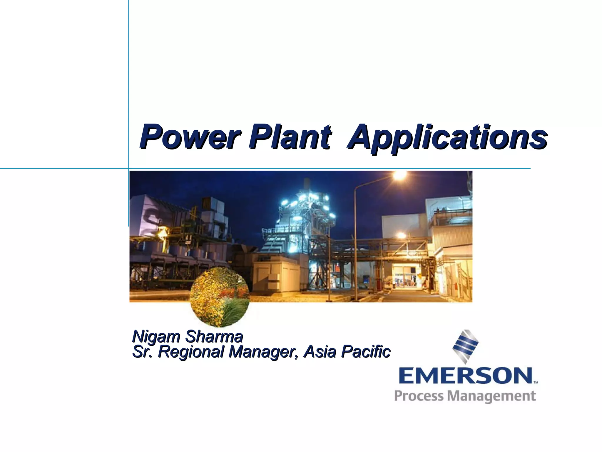
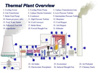
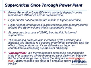
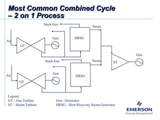
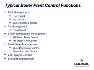
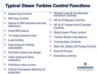
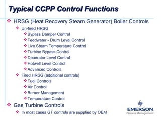
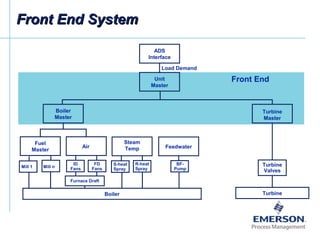
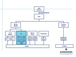
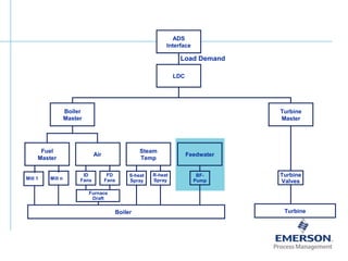
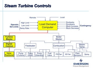
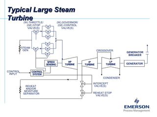
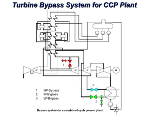
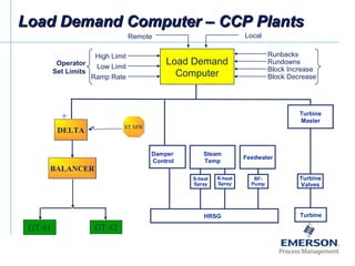
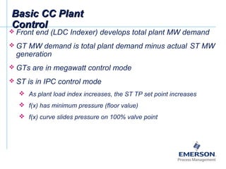
Thermal power plants generate electricity through combustion of fuels like coal and gas. The key components are the boiler, steam turbine, and electric generator. Control systems regulate critical functions like fuel and air management, steam temperatures, feedwater levels, and turbine speed. Supercritical plants operate at higher pressures and temperatures for greater efficiency. Combined cycle plants further improve efficiency by capturing waste heat from gas turbines to power additional steam turbines.
Types of air preheaters and its advantagesPreeti Agarwal
A very basic word to word meaning is a device used to heat the air before further use is called as Air Preheater. They are also recognized as air heaters or air-heating pipe. It is designed to exchange heat energy with desuperheaters. Desuperheater is a Device which is been used to reduce the temperature of the steam in a high heat generation plants where large amount of heat energy or steam is released in the atmosphere.
The writeup details the Heat Balance of BHEL 210 MW Turbine Cycle. The Input and Output steam condition of Turbines, Extractions, Deaerator, LP Heaters, Condensers etc have been computed as per the specifications of the turbine manufacturer
The Presentation discusses the Air-Heater Performance Indices and the Boiler Performance calculation. One can Calculate the air ingress in the air-heater and the boiler and losses incurred thereby. The presentation also describes in details about the boiler efficiency and its calculation.
Heat rate is the pulse rate of a power plant to know the health of the plant.
Net heat rate is the single parameter that encompasses total performance indices of a power plant.
The presentation details about the Boiler Operation specifically while lightup of boiler and loading of boiler. the course participants discuss in details about the operations carried in their respective power stations
the water that reaches the surface is not hot enough to produce steam, it can still be used to produce electricity by feeding it into a Binary Power Plant. The hot water is fed into a heat exchanger. The heat from the water is absorbed by a liquid such as isopentane which boils at a lower temperature. The isopentane steam is used to drive turbines, producing electricity. The isopentane then condenses back to its liquid state and is used again.
Thermal Power plant familarisation & its AuxillariesVaibhav Paydelwar
PPT in Relation to Power Plant familarisation, Coal to Electricity Basics,Power Plant cycles, Concepts of Supercritical Technology Boiler, Concepts Of BTG Package as well as Balance of Plant
introduction to thermal powerplant,type of thermal powerplant,captive powerplant,rankin cycle,co-generation powerplant,subcritical powerplant,supercritical powerplant,theory of operation,working principle,parts of powerplant,boiler,turbine,etc
INTRODUCTION
THERMODYNAMIC CYCLE OF STEAM FLOW
RANKINE CYCLE (IDEAL , ACTUAL ,REHEAT)
LAYOUT OF STEAM POWER PLANT
MAJOR COMPONENTS AND THEIR FUNCTIONS
ALTERNATOR
EXCITATION SYSTEM
GOVERNING SYSTEM
In any thermal power generation plant, heat energy converts into mechanical work. Then it is converted to electrical energy by rotating a generator which produces electrical energy.
Power Plant Regenerative feed heating and design aspects of Feed Heaters.This is a ppt for beginners in Power Plant Engineering.Also discusses Heat Transfer and Rankine cycle.
Kubernetes & AI - Beauty and the Beast !?! @KCD Istanbul 2024Tobias Schneck
As AI technology is pushing into IT I was wondering myself, as an “infrastructure container kubernetes guy”, how get this fancy AI technology get managed from an infrastructure operational view? Is it possible to apply our lovely cloud native principals as well? What benefit’s both technologies could bring to each other?
Let me take this questions and provide you a short journey through existing deployment models and use cases for AI software. On practical examples, we discuss what cloud/on-premise strategy we may need for applying it to our own infrastructure to get it to work from an enterprise perspective. I want to give an overview about infrastructure requirements and technologies, what could be beneficial or limiting your AI use cases in an enterprise environment. An interactive Demo will give you some insides, what approaches I got already working for real.
Software Delivery At the Speed of AI: Inflectra Invests In AI-Powered QualityInflectra
In this insightful webinar, Inflectra explores how artificial intelligence (AI) is transforming software development and testing. Discover how AI-powered tools are revolutionizing every stage of the software development lifecycle (SDLC), from design and prototyping to testing, deployment, and monitoring.
Learn about:
• The Future of Testing: How AI is shifting testing towards verification, analysis, and higher-level skills, while reducing repetitive tasks.
• Test Automation: How AI-powered test case generation, optimization, and self-healing tests are making testing more efficient and effective.
• Visual Testing: Explore the emerging capabilities of AI in visual testing and how it's set to revolutionize UI verification.
• Inflectra's AI Solutions: See demonstrations of Inflectra's cutting-edge AI tools like the ChatGPT plugin and Azure Open AI platform, designed to streamline your testing process.
Whether you're a developer, tester, or QA professional, this webinar will give you valuable insights into how AI is shaping the future of software delivery.
Dev Dives: Train smarter, not harder – active learning and UiPath LLMs for do...UiPathCommunity
💥 Speed, accuracy, and scaling – discover the superpowers of GenAI in action with UiPath Document Understanding and Communications Mining™:
See how to accelerate model training and optimize model performance with active learning
Learn about the latest enhancements to out-of-the-box document processing – with little to no training required
Get an exclusive demo of the new family of UiPath LLMs – GenAI models specialized for processing different types of documents and messages
This is a hands-on session specifically designed for automation developers and AI enthusiasts seeking to enhance their knowledge in leveraging the latest intelligent document processing capabilities offered by UiPath.
Speakers:
👨🏫 Andras Palfi, Senior Product Manager, UiPath
👩🏫 Lenka Dulovicova, Product Program Manager, UiPath
State of ICS and IoT Cyber Threat Landscape Report 2024 previewPrayukth K V
The IoT and OT threat landscape report has been prepared by the Threat Research Team at Sectrio using data from Sectrio, cyber threat intelligence farming facilities spread across over 85 cities around the world. In addition, Sectrio also runs AI-based advanced threat and payload engagement facilities that serve as sinks to attract and engage sophisticated threat actors, and newer malware including new variants and latent threats that are at an earlier stage of development.
The latest edition of the OT/ICS and IoT security Threat Landscape Report 2024 also covers:
State of global ICS asset and network exposure
Sectoral targets and attacks as well as the cost of ransom
Global APT activity, AI usage, actor and tactic profiles, and implications
Rise in volumes of AI-powered cyberattacks
Major cyber events in 2024
Malware and malicious payload trends
Cyberattack types and targets
Vulnerability exploit attempts on CVEs
Attacks on counties – USA
Expansion of bot farms – how, where, and why
In-depth analysis of the cyber threat landscape across North America, South America, Europe, APAC, and the Middle East
Why are attacks on smart factories rising?
Cyber risk predictions
Axis of attacks – Europe
Systemic attacks in the Middle East
Download the full report from here:
https://sectrio.com/resources/ot-threat-landscape-reports/sectrio-releases-ot-ics-and-iot-security-threat-landscape-report-2024/
Search and Society: Reimagining Information Access for Radical FuturesBhaskar Mitra
The field of Information retrieval (IR) is currently undergoing a transformative shift, at least partly due to the emerging applications of generative AI to information access. In this talk, we will deliberate on the sociotechnical implications of generative AI for information access. We will argue that there is both a critical necessity and an exciting opportunity for the IR community to re-center our research agendas on societal needs while dismantling the artificial separation between the work on fairness, accountability, transparency, and ethics in IR and the rest of IR research. Instead of adopting a reactionary strategy of trying to mitigate potential social harms from emerging technologies, the community should aim to proactively set the research agenda for the kinds of systems we should build inspired by diverse explicitly stated sociotechnical imaginaries. The sociotechnical imaginaries that underpin the design and development of information access technologies needs to be explicitly articulated, and we need to develop theories of change in context of these diverse perspectives. Our guiding future imaginaries must be informed by other academic fields, such as democratic theory and critical theory, and should be co-developed with social science scholars, legal scholars, civil rights and social justice activists, and artists, among others.
"Impact of front-end architecture on development cost", Viktor TurskyiFwdays
I have heard many times that architecture is not important for the front-end. Also, many times I have seen how developers implement features on the front-end just following the standard rules for a framework and think that this is enough to successfully launch the project, and then the project fails. How to prevent this and what approach to choose? I have launched dozens of complex projects and during the talk we will analyze which approaches have worked for me and which have not.
Slack (or Teams) Automation for Bonterra Impact Management (fka Social Soluti...Jeffrey Haguewood
Sidekick Solutions uses Bonterra Impact Management (fka Social Solutions Apricot) and automation solutions to integrate data for business workflows.
We believe integration and automation are essential to user experience and the promise of efficient work through technology. Automation is the critical ingredient to realizing that full vision. We develop integration products and services for Bonterra Case Management software to support the deployment of automations for a variety of use cases.
This video focuses on the notifications, alerts, and approval requests using Slack for Bonterra Impact Management. The solutions covered in this webinar can also be deployed for Microsoft Teams.
Interested in deploying notification automations for Bonterra Impact Management? Contact us at sales@sidekicksolutionsllc.com to discuss next steps.
Accelerate your Kubernetes clusters with Varnish CachingThijs Feryn
A presentation about the usage and availability of Varnish on Kubernetes. This talk explores the capabilities of Varnish caching and shows how to use the Varnish Helm chart to deploy it to Kubernetes.
This presentation was delivered at K8SUG Singapore. See https://feryn.eu/presentations/accelerate-your-kubernetes-clusters-with-varnish-caching-k8sug-singapore-28-2024 for more details.
3. Types of PlantsTypes of Plants
Thermal Power Plants
Coal Fired Utility
Oil and Gas Fired Plants
Bio-fuel Plants
Gas Turbine Plants
Gas and Oil Fired
Simple Cycle Gas Turbine Plants
Combined Cycle HRSG and Steam Turbine Plants (CCP)
Cogeneration Plants (Industrial or District Heating)
Oil & Gas Fired CCP
Bio-Fuel CFB plants
Nuclear Plants
√√
√√
√√
XX
4. Thermal Plant OverviewThermal Plant Overview
1. Cooling Tower 2. Cooling Water Pump 3. 3-phase Transmission Line
4. Unit Transformer 5. 3-phase Electric Generator 6. Low Pressure Turbine
7. Boiler Feed Pump 8. Condensor 9. Intermediate Pressure Turbine
10. Steam governor valve 11. High Pressure Turbine 12. Deaerator
13. Feed Water Heater 14. Coal Conveyor 15. Coal Hopper
16. Pulverised Fuel Mill 17. Boiler Drum 18. Ash Hopper
19. Superheater 20. Forced Draught Fan 21. Reheater
22. Air Intake 23. Economiser 24. Air Preheater
25. Electrostatic Precipitator 26. Induced Draught Fan 27. Chimney Stack
5. Boilers or Steam Generators
Generate steam at desired rate, pressure and temperature by
burning fuel in its furnace.
The boiler is that part of the steam generator where phase change
(or boiling) occurs from liquid (water) to vapour (steam), essentially
at constant pressure and temperature.
Steam Turbine
Steam turbine is a mechanical device that extracts thermal energy
from pressurized steam, and converts it into useful kinetic
(rotational) energy which rotates the steam turbine.
Most steam turbines rotate at 3000 rpm or 3600 rpm.
Electric Generator
Electrical generator is a device that converts kinetic energy to
electrical energy, generally using electromagnetic induction.
Electric Generators are rotated by Steam Turbines at 3000 rpm or
3600 rpm
Major ComponentsMajor Components
7. Basic Boiler TypesBasic Boiler Types
Up to an operating pressure of around 190Kg Bar in the
evaporator part of the boiler, the cycle is Sub-Critical. In this case
a drum-type boiler is used because the steam needs to be
separated from water in the drum of the boiler before it is
superheated and led into the turbine.
Above an operating pressure of 220Kg Bar in the evaporator part
of the Boiler, the cycle is Supercritical. The cycle medium is a
single phase fluid with homogeneous properties and there is no
need to separate steam from water in a drum. Drumless or Once-
through boilers are therefore used in supercritical cycles.
Advanced Steel types must be used in Supercritical boilers for
components such as the boiler and the live steam and hot reheat
steam piping that are in direct contact with steam under elevated
conditions
Sub-critical Boilers: Steam conditions up to 220Kg bas/ 540°C
are achieved
Supercritical Boilers: Steam conditions up to 300 Kg
Bar/600°C/620°C are achieved using steels with 12 % chromium
content.
8. Supercritical Once Through Power PlantSupercritical Once Through Power Plant
Power Generation Cycle Efficiency primarily depends on the
temperature difference across steam turbine.
Higher boiler outlet temperature results in higher difference.
Higher steam temperatures is also linked to increased pressures
to keep the steam volume within manageable limits.
At pressures in excess of 220Kg bar, the fluid is termed
supercritical.
The increased pressure also increases cycle efficiency and,
although this increase is a second-order effect compared with the
effect of temperature, but it can still make an important
contribution to increasing overall plant efficiency.
“SupercriticalSupercritical" is a thermodynamic expression describing the
state of a substance where there is no clear distinction between
the liquid and the gaseous phase (i.e. they are a homogenous
fluid). Water reaches this state at a pressure above around 220
Kg Bar.
9. Supercritical Once Through Power PlantSupercritical Once Through Power Plant
Supercritical coal fired power plants have higher efficiencies
of almost 45%
Supercritical Power plants have lower emissions than sub-
critical plants at any given power output.
11. HP
FW
HTR
LP
FW
HTR
HP L PSecondary
Super
Heater
Power Plant ProcessPower Plant Process
MapMap
Once-Thru Boiler
BFP
Water Vapor &
Scrubbed Gases
Load
Gen.
Turbine
Econ-
omizer
Re-
Heat
Condenser
ID
Fan
Precipitators
Stack
Gas
Scrubber
Emissions
Monitor
Flyash
Deaerator
Cooling
Water
Bottom
Ash
System
Economizer
Hoppers
F D
Fan
Settling
Pond
Ash
Transfer
Water
Clean-up
Cond.
Pump
General
Water
Sump
Coal
Bunker
Conveyors
Pulverizers
P A
Fan
Feeder
Primary
Super
Heater
IP
Air Heater
BOTTOM
ASH
HOPPER
12. Circulating Fluidized Bed BoilersCirculating Fluidized Bed Boilers
A bed of sand, ash and fuel particles
is fluidized by the combustion air,
which is blown into the bed through
the bottom.
Due to high air/flue gas velocity the
fuel is carried over in the combustion
gases.
The solid material is then separated in
a cyclone and recycled to the lower
section of the bed.
CFB combustion process is ideally
suited to burning
low-quality fuels,
fuels with a high moisture content
'waste-type' fuels.
All coals, lignite, petroleum coke,
biomass, waste coal, refuse-derived
fuels, agricultural and pulping waste,
and municipal solid waste
13.
14. Typical Large Steam TurbineTypical Large Steam Turbine
Steam turbine is a mechanical device that extracts thermal energy from
pressurized steam, and converts it into useful kinetic (rotational)
energy by expansion.
The expansion takes place through a series of fixed blades (nozzles)
and moving blades.
The moving blades rotate on the turbine rotor and the fixed blades are
concentrically arranged within the circular turbine casing which is
substantially designed to withstand the steam pressure.
Most steam turbines rotate at 3000 rpm or 3600 rpm.
15. Basic Steam TurbinesBasic Steam Turbines
The Turbine designs for a Supercritical plant are similar to the
sub-critical except that special materials required for the casings
and walls for withstanding high Temperatures and pressures in
Supercritical Steam Turbines.
High Pressure (HP) Turbine: In order to cater for the higher
steam parameters in supercritical cycles, materials with an
elevated chromium content which yield higher material strength
are selected.
Intermediate Pressure (IP) Turbine Section: In supercritical
cycles there is a trend to increase the temperature of the reheat
steam that enters the IP turbine section in order to raise the
cycle efficiency. As long as the reheat temperature is kept at
560 DEGC there is not much difference in the IP section of Sub
critical and Super Critical plants.
Low Pressure (LP) Turbine Section: The LP turbine sections
in supercritical plants are not different from those in subcritical
plants.
16. Combined Cycle PlantsCombined Cycle Plants
Term Combined Cycle is used to describe process that uses
combination of more than one thermodynamic cycles.
Combined Cycle Power Plant (CCPP) means a combination of
gas turbine generator (Brayton cycle) with turbine exhaust
waste heat boiler and steam turbine generator (Rankine cycle)
for the production of electric power.
CCPP Common Combinations
One CT and One Steam Turbine (1 on 1)
Two CTs and One Steam Turbine (2 on 1)
X CTs and Y STs (X on Y)
CTs always paired with a HRSG
2 on 1 common - all generators work out to be comparable size
18. Combined Cycle Power GenerationCombined Cycle Power Generation
Thermal Efficiency = 45-55%
35-40% Electricity
Generator
6% Aux. Power + Losses
Air
100% Fuel
Combuster
Stack
20%
Compressor Turbine
28%Steam Condenser
HRSG
Steam
Supplementary
Fuel (Optional)
Exhaust
Gas
Steam TurbineGenerator
12-15% Electricity
Lake
19. Typical Combined Cycle PlantTypical Combined Cycle Plant
Gas Supply Station
Gas Supply Gas Turbine Stack
Heat Recovery Steam Generator
HRSG Stack
Generator
Transformer
Transmission
Deaerator
Boiler Feed Pump
Cooling
Towers
Condensate
Extraction Pump
Generator
Transformer Transmission
Gas Turbine
IP LP Generator
Cooling Water
Switch Yard
Demineralization Plant
Raw Water
FW
FW
Switch Yard
Air Intake
Condenser
Bypass
Damper
20. Most Common Combined CycleMost Common Combined Cycle
– 2 on 1 Process– 2 on 1 Process
Air
Air
GT
GT
HRSG
HRSG
ST
Gen
Gen
Gen
Steam
Steam
Stack Gas
Stack Gas
Legend
GT – Gas Turbine Gen - Generator
ST – Steam Turbine HRSG – Heat Recovery Steam Generator
21. Common Cogeneration PlantsCommon Cogeneration Plants
Cogeneration is the simultaneous production of power/electricity,
hot water, and/or steam from one fuel.
Cogeneration plants can reach system efficiencies exceeding 80%
Industrial Plants
Multi utility plants; Electricity, Process Steam, Heating Steam, Hot
water, Chillers etc.
District Heating Plants
Extraction steam for residential heating
Oil or Gas fired
Combined Cycle Cogen
Conventional Boilers Cogen
Circulating Fluidized Bed Boilers
Low Calorific Value, high moisture, low Sulphur fuels
Bagasse, Rice husk, Rice Straw, Wood Chips etc
25. Typical Boiler Plant Control FunctionsTypical Boiler Plant Control Functions
Fuel Management
Fuel control
Mill control
Burner Safety & control
Air Management
Fans Control
Steam temperature Management
SH Steam Temp Control
RH Steam Tem Control
Feed Water Management
Boiler Drum Level Control
Deaerator Level Control
Soot Blower Controls
Emission Management
26. Typical Steam Turbine Control FunctionsTypical Steam Turbine Control Functions
Speed loop Control
MW loop Control
Speed or MW demand and rate
selections
Initial MW pickup
1st stage pressure loop
Load limiting
Inlet pressure limiting
(adjustable)
Fail safe turbine trip design
Valve testing & Valve
calibration
Individual valve curves
Critical Overspeed detection &
protection
Hotwell Level & Condensate
extraction Controls
HP & LP Bypass Controls
HP & LP Heater level Cascade
Controls
Gland steam Press control
Turbine Stress Calculations
Turning Gear Controls
Main Oil, Safety Oil Pumps Control
Seal Oil Pumps
Extraction controls
27. Typical CCPP Control FunctionsTypical CCPP Control Functions
HRSG (Heat Recovery Steam Generator) Boiler Controls
Un-fired HRSG
Bypass Damper Control
Feedwater - Drum Level Control
Live Steam Temperature Control
Turbine Bypass Control
Deaerator Level Control
Hotwell Level Control
Advanced Controls
Fired HRSG (additional controls)
Fuel Controls
Air Control
Burner Management
Temperature Control
Gas Turbine Controls
In most cases GT controls are supplied by OEM
28. Typical Balance of Plant ControlsTypical Balance of Plant Controls
Balance of Plant Controls (Miscellaneous Controls)
Water Treatment Plant Controls
Circulating Water System
Raw Water system
Turbine Cooling Oil Temperature Controls
Generator Cooling Oil Temperature Controls
Ash Handling System Controls
Fuel Handling Systems
Fuel Skid Controls (CCPP)
Coal Handling System Controls
Environmental Controls
Flue Gas De-Sulphurization Controls
Scrubber Controls
Motor Controls
Electrical Controls & Monitoring
29. Basic level:
Single drive control with electrical protections, auto/manual modes
Single loop control with protection of actuators, auto/manual modes
Interlocks between the control loops and drives
Control of technological groups for Boiler and Turbine:
Coordinated loops control (common setpoint, interactions)
Cross interlock feedbacks and priorities
Sequences
Turbine start-up, roll-off, and other turbine coordinated controls
Burner Management System
Coordinated Unit Control:
LDC - Load Demand Computer - selection of boiler / turbine modes
Unit remote control from Dispatch Center
Main unit control sequences
Run-backs & Run-ups
Concept of a Unit ControlConcept of a Unit Control
30. Binary Control
Drive Control Standards for:
low voltage motors
high voltage motors
open/close valves or dampers
electrical actuators
Sequential Control
Features of a sequence:
consists of a sequence head and sequence steps
sets time relations between performed steps
allows start, stop and resume by operator
incorporates emergency logic and procedures
incorporates interaction logic and operator’s permissives
Concept of a Unit ControlConcept of a Unit Control
31. Modulating Control
Control Structures:
Basic level - single loop executing a direct control of actuator
Cascade level calculating setpoint for basic level loop
Coordinating level responsible for unit load and cross feedbacks
between parts of the unit
Supervisory optimization structure, which calculates corrections for
other control loops, based on feed-forward and Smith prediction
philosophy
Control Algorithms:
Mathematical algorithms
Universal PID type (PID, PIDFF)
Dedicated for power applications: Smith predictor, drum level
correction, steam table, PID with variable parameters
Value tracking for bumpless transfer during auto / manual switch
Advanced algorithms
Concept of a Unit ControlConcept of a Unit Control
33. Coordinated Unit ControlsCoordinated Unit Controls
ADS
Interface
Unit
Master
Boiler
Master
Fuel
Master
Air
Steam
Temp Feedwater
Boiler Turbine
Turbine
Master
Mill 1 Mill n
ID
Fans
FD
Fans
Furnace Draft
S-heat
Spray
R-heat
Spray
BF-
Pump
Turbine
Valves
Load Demand
34. Front End
Front End SystemFront End System
ADS
Interface
Unit
Master
Boiler
Master
Fuel
Master
Air
Steam
Temp Feedwater
Boiler Turbine
Turbine
Master
Mill 1 Mill n
ID
Fans
FD
Fans
Furnace Draft
S-heat
Spray
R-heat
Spray
BF-
Pump
Turbine
Valves
Load Demand
36. Invented by Westinghouse for coordinated unit control
Allows to control a unit in different modes of operation:
Turbine Follow Mode: Turbine control with throttle pressure –
The turbine follows the boiler load, LDC tracks the actual unit load and
calculates setpoint for the boiler (MW loop is not in use)
Boiler Follow Mode: Boiler control with live steam pressure –
The boiler adapts the steam generation to the consumption required by
the turbine, LDC tracks the actual unit load and calculates the setpoint
for turbine valve position (MW loop is not in use)
Coordinated Control Mode:
Either turbine or boiler controls live steam pressure and boiler or turbine
respectively (MW loop is in use for turbine or boiler)
Load Demand ComputerLoad Demand Computer
37. LDC is a software model of the process, which calculates
on-line all required control setpoints using “feed-forward”
Operator sets the required load or MW demand
LDC calculates the main setpoints separately for the boiler
and the turbine control structures
The structure for boiler recalculates setpoints for loops
controlling air and fuel
Tunable function generator algorithms calculate setpoints for
loops controlling the actuators
LDC allows to keep unit in automatic control also during
runbacks or trips
Load Demand ComputerLoad Demand Computer
38. Four Modes
Coordinated
Turbine Follow
Boiler Follow
Manual (separated)
Bumpless transfer between all modes
Interlocks prevent Unit Master from controlling unless either
Boiler or Turbine Master in Auto
Rate limiting on ramped signals
Load Demand ComputerLoad Demand Computer
41. Turbine Master (Variable or Sliding Pressure)
Alternative to fixed pressure mode
Throttle pressure varied with load while turbine valves
remain in fixed position
Valves allowed to move on load changes for fast
response
Throttle pressure allowed to vary to maintain proper
valve position
Not suitable for all boilers
Turbine MasterTurbine Master
42. Boiler Master
Sets boiler firing rate
Interlocked to lower control loops
Dynamic control to improve responsiveness
Runbacks and rundowns based on boiler capabilities
Boiler MasterBoiler Master
44. FuelFuel
MasterMaster
Fuel Master
Develops base control signal for coal mills
Performs fuel/air cross limiting
Incorporates a mill model to improve coal flow
measurement
Uses boiler as calorimeter
45. FuelFuel
MasterMaster
Mill Controls
Regulates coal flow
Regulates primary air flow
Regulates coal/air temperature leaving mill
Feeder overrides on high mill amps and/or mill differential
pressure
Primary air flow takes priority over coal/air temp.
Includes interlocks to air dampers for safety and interface
to BMS
47. Air FlowAir Flow
ControlControl
FD Fan Control
Controls combustion air flow
Firing rate sets air flow
requirement
Includes damper interlocks
Interlocked to ID fans for auto
mode
Includes fuel/air cross limiting
(O2 trimming)
48. Air FlowAir Flow
ControlControl
Furnace Draft Control
Regulates ID fans to provide proper exhausting force for gas flow
through boiler
Uses FD fan demand as feedforward
Utilizes three furnace pressure transmitters (middle-of-three) for
control
Fully meets NFPA requirements for:
Rapid closing of ID inlet dampers on MFT
Directional blocking on low furnace pressure
Includes damper interlocks for starting/stopping
50. FeedwaterFeedwater
ControlControl
Feedwater Control
Regulates feedwater flow and
controls drum level
Two modes of operation
Single element for use
during startup
Three element for
normal operation
Drum level signals are
density compensated
53. SteamSteam
TemperatureTemperature
Superheat Temperature Control
Regulates main steam temperature
Standard consists of two stage attemperation
Includes integral windup protection
Includes interlocks for spray and block valves
54. SteamSteam
TemperatureTemperature
Reheat Temperature Control
Regulates reheat steam temperature thru the use of sprays &
burner tilting arrangement
System tracks until spray valve open
Interlocks for both spray and block valves included
55. Furnace 2 nd
S.H.
PID
PID
PID
PID
X
Firing Rate
Boiler
Master
Desired Spray
(20%)
WW Outlet
Temp
LDC
Out
Econo
mizer
Fuel/Air
4th
S.H.
3rd
S.H.
PID
FW Flow
Control
FW/FR
ratio
DMC
Algorithm
SUM
RH
Tilts/Damper
Setpoints
2nd
, 3rd
and 4th
SH
1st
S.H.
APC Steam Temperature ControlAPC Steam Temperature Control
SchemeScheme
56. A Safety System
Permits safe start-up, operation, and shutdown of the boiler
Supervises Fuel insertion/withdrawal from boiler conforming to
established safety standards
Monitors and controls igniters and burners
Separate Flame Scanners used to detect igniter and main flames
Three type of flame scanners
Ultraviolet, typically used for natural gas and light oils
Infrared, typically used for medium to heavy oils and pulverized coal
All Fuels, typically used with gas igniters & coal as main fuel
Other Field Devices
Safety shut-off valves
Pressure, temperature, flow & valve position limit switches
Blowers to cool scanners or provide combustion air for igniters
Burner Management SystemBurner Management System
DefinitionDefinition
57. Critical safety signals are wired as redundant I/O for maximum boiler
safety.
An automatic start sequence ensures correct completion of boiler air
purge and satisfies safety permissives before fuel firing, preventing
operator error.
Continued monitoring of boiler conditions actuates a safety shutdown trip
if unsafe conditions develop.
Operator maintains control capabilities from the operator console or
burner front digital logic stations.
First-out indications are provided for identification of the cause of boiler
trip
Automatic Boiler Purge Prior to Restart
Flame Detection, Monitoring & protection
Master Fuel Trip
Burner/Mill Start-Up and Shutdown
Sequences
Safety Interlocking
Alarming of Abnormal Conditions
Burner Management SystemBurner Management System
58. 6 to 8 Pulverizers (Mills) needed in each boiler to supply
Pulverized coal to the burners
One mill normally supplies pulverized coal to one burner
level. Additional mills supply each additional burner level
on a one-for-one basis.
There are between four and eight burners per level. This
depends upon the type of furnace, e.g. wall fired,
tangential, split furnace, etc.
With dual fuel firing, there will also be oil guns /gas nozzles
on one or more burner levels. There will be four to eight
guns / nozzles per level.
Mills, Burners and LevelsMills, Burners and Levels
61. The Burner "Front"The Burner "Front"
Startup Sequence
(Light-off by burner pairs)
- Purge air-10 Minutes
- Purge air Off
- Open Dampers
- Ignition Spark ON
- Ignition Valve OPEN
- Prove Igniter ON
- Main Fuel ON
- Prove Main Flame ON
- All Ignition OFF on
Combustion Control
Fuel
Ignition
Transformer
Igniter
Damper
Damper
Purge
Air
Main Burner
Ignition
Flame
Main
Flame
Ignition
Flame
Det.
Main
Flame
Det
Cooling
Air
Wind
Box
62. Enhanced safety and availability
Greater operational flexibility
Significant auxiliary fuel savings
Continuous safety monitoring
Consistent start-up and operation
Full integration of all facets of the firing system
Integrated Air damper controls
Improved plant availability
Reduced maintenance costs
Prevention of boiler explosion
NFPA 8502 code compliance
Expandable solutions
Ovation BMS FeaturesOvation BMS Features
63. Turbine
Master
Boiler
Master
Feedwater Combustion
Fuel
Valve
FD Fan ID Fan
Pump
(Turbine)
Pump
(Shaft)
Pump
(Standby)
Load Demand
Computer
High Limit
Low Limit
Ramp Rate
Operator
Set Limits
Runbacks
Rundowns
Block Increase
Block Decrease
Contingency
Digital
Control
LocalRemote
Valve
Positioner
Pass
Dampers
Spray
Steam
Temp.
Steam Turbine ControlsSteam Turbine Controls
64. Ovation Turbine Control ArchitectureOvation Turbine Control Architecture
Redundant systems
- Processor - I/O interface
- Power supplies - Network
interface
System same as rest of plant
Controller hardware and I/O
User Interfaces
Network
Standard I/O cards for specialized
turbine applications
Speed cards
Valve cards
66. Speed Detector ModuleSpeed Detector Module
5ms update rate for overspeed
detection
Variable update rate for speed
regulation
Controller-independent speed detection
and tripping using dual on-board form
C outputs for fast reaction to over
speed conditions
Open-wire detection for low resistance
source less than 5000 Ohms
Redundant power feeds
1000V dielectric withstand electrical
isolation between logic signal and field
inputs
Hot swap capability
67. Self calibrating & Self Diagnostics
PI control loop with 10 millisecond loop time
Programmable PI gain and integral time constants
Normal mode or SLIM interface for local manual operation
Up to three redundant servo valve actuator coil drive outputs
Supports redundant coil and redundant LVDT capability (Redundant configuration)
Interfaces to LVDT interface to primary excitation and dual secondary feedback
windings
24/48V dc input for emergency valve closure independent of controller
16 bit micro-controller watchdog timer for servo valve actuator coil drive
Supports single mode (full arc) or sequential (partial arc) modes of valve operation
Watchdog timer for I/O bus
Redundant configuration option
Redundant 24V power auctioneering
Local calibration & tuning capability without trim pots
Open-coil and shorted-coil diagnostics
Runs seating and back-seating logic
Valve Positioner ModuleValve Positioner Module
68. Self calibrating & Self Diagnostics
PI control loop with 10 millisecond loop time
Programmable PI gain and integral time constants
Normal mode operation only 2 servo valve actuator coil drive outputs
Supports redundant coil and dual LVDT capability.
2 DC-LVDT or AC-LVT outputs & 2 DC-LVDT or AC-LVT inputs
16 bit micro-controller
Watchdog timer for servo valve actuator coil drive
Watchdog timer for I/O bus
Redundant feedback option for AC-LVT
Redundant 24V power auctioneering
Local calibration & tuning capability without trim pots
Open-coil and shorted-coil diagnostics
Runs seating and back seating logic
Hot swap capability
Servo Driver ModuleServo Driver Module
69. Main Stop Valves or Throttle Valves, used primarily during
start-up, machine protection
Governor Valves or Control Valves, control the turbine over
most of the operating range
Reheat Stop Valve, on-off type valve to backup the
intercept valve
Intercept Valve, used to prevent steam from entering
turbine after load loss
Full Arc Admission / Partial Arc Admission
Single Valve Mode / Sequential Valve Mode
Steam Turbine Valve TerminologySteam Turbine Valve Terminology
70. Governor Control FunctionsGovernor Control Functions
Control of:
Turbine stop valves
Control valves
Reheat stop valves
Intercept valves
Monitor & Control of:
Speed
Main steam pressure
Chest pressure
1st stage pressure
Reheat pressure
Load
71. Typical Large SteamTypical Large Steam
TurbineTurbine
HP
TURBINE
IP
TURBINE
LP
TURBINE
SPEED
SENSING
CONTROL
SYSTEM
CONTROL
INPUT
STEAM
GEN
INTERCEPT
VALVE(S)
REHEAT STOP
VALVE(S)
REHEAT
AND/OR
MOISTURE
SEPARATOR
CONDENSER
(W) GOVERNOR/
(GE) CONTROL
VALVE(S)
(W) THROTTLE/
(GE) STOP
VALVE(S)
CROSSOVER
GENERATOR
GENERATOR
BREAKER
73. Typical Startup and Loading ProgramsTypical Startup and Loading Programs
Pre Warm
Pre Roll Conditions
1st Stage Shell Metal Temp Change
Hot Reheat Temp Change
HP allowable Ramp Rate
Reheat allowable Ramp Rate
1st Stage Shell Steam Temp
Speed Soaks (1000, 3000 and 3600 RPMs)
Initial Load Pickup and Soak
74. Steam Turbine System AuxiliariesSteam Turbine System Auxiliaries
Motor Operated Valves
Solenoid Operated Valves
Vapor Extractors
Turning Gear
Turbine Drain Valves
Jacking Oil Pumps
Gland Steam System
Seal Steam System
Lube Oil System
Auxiliary Steam System
Emergency Leak-off System
Vacuum Breakers
Bentley Nevada Modbus Link
Turbine Supervisory
75.
76. Turbine bypass systems can contribute to flexible plant
operation mainly by supporting:
Repeatedly attainable fast startups with the greatest possible regard
to the lifetime of heavy-walled components.
Quickest possible restoration of power supply to the grid after any
disturbance
Saves startup time by avoiding boiler trip on turbine trip.
Ensures high reliability and availability of the plant
Bypass systems contribute to the overall target of safe and
efficient supply of electric power at minimum total cost.
Steam bypass systems bring substantial fuel savings while
they solve many of the problems caused by using baseload
generating units for cyclic operation
Turbine Bypass SystemTurbine Bypass System
77. The steam bypass system is generally used during the
following modes of operation:
Start-up and shutdown,
Steam turbine trip,
Steam turbine no-load or low-load operation
Fast Run back
Fast load throw off
House load operation
Turbine Bypass SystemTurbine Bypass System
80. Typical Large Steam TurbineTypical Large Steam Turbine
Extraction Steam and Heater SystemsExtraction Steam and Heater Systems
I P
Turbine
H P
Turbine
High
Pressure
Heaters
High
Pressure
Heaters
High
Pressure
Heaters
Boiler
Feed
Pumps
Low
Pressure
Heater
Low
Pressure
Heater
Deaerater
Heated
Feedwater
to Boiler
BFP Recirc.
Condensate
To Hotwell
LP Turbine
81. Automatic Turbine Start-up Control &Automatic Turbine Start-up Control &
Rotor Stress MonitoringRotor Stress Monitoring
Safe Turbine Start-up and Shut down Sequencing
OEM guidelines are incorporated using the flowcharts and
rotor stress constants
ATC mode automatically determines:
Speed & Load Targets
Speed Rates & Speed Holds
Load Rates & Load Holds
Run backs
Integral Turbine Protections
82. Typical ATC and RSM ProgramsTypical ATC and RSM Programs
HP and IP rotor stress calculations
Steam chest metal required temperature calculations
Turning gear checks before startup
Eccentricity and vibration monitoring
Water detection and drain valve control
Bearing temperature monitoring
Generator monitoring and checks before synchronization
Heat soak calculations allowing for shorter heat soak time
84. Front end (LDC Indexer) develops total plant MW demand
GT MW demand is total plant demand minus actual ST MW
generation
GTs are in megawatt control mode
ST is in IPC control mode
As plant load index increases, the ST TP set point increases
f(x) has minimum pressure (floor value)
f(x) curve slides pressure on 100% valve point
Basic CC PlantBasic CC Plant
ControlControl
85. Emerson Gas TurbineEmerson Gas Turbine
ControlControl Automatic startup and shutdown
Surge control limited starting and under load
Feed-forward fuel control schedule during
starting
Temperature override control during starting
Speed control from tuning gear to minimum
load
Load control from minimum to base load
Loading rate control
Temperature control at load
Minimum and maximum limits on fuel flow
86. Ovation Gas Turbine Controls OfferOvation Gas Turbine Controls Offer
Numerous AdvantagesNumerous Advantages Advanced control and turbine protection
schemes
Local and remote operation capability
Improved data acquisition for predictive
maintenance and scheduling
Integrated power and BOP control
systems
Maximize efficiency through load
management
More precise and reliable fuel control
Advanced graphical interface
Historical logging and trending
Diagnostics for preventative maintenance
87. Modern Power Plant ConsiderationsModern Power Plant Considerations
Power industry is experiencing a dramatic changes fueled by Deregulation and
consolidation.
Older business models are changing to cope with Competition between utilities,
environmental concerns, and increasing power demand.
Availability, reliability, efficiency & lesser operating costs have become key
elements of everyday plant operation considerations.
Today’s control system networks have become Information networks
Modern power plants tending to achieve vertical and horizontal integration of
plant wide controls under single hardware/software platform, using Smart Filed
Devices and Industrial standard communication across various layers of
information & control networks.
Integrated Plant Optimization suites enable efficient optimized continuous plant
controls throughout the plant operation range.
Plant Web Digital architecture enables easy integration of field devises while
ensuring high quality field intelligence made available to the right persons,
minimizing operational & maintenance costs while maximizing safety.
Integrated Plant Simulator for efficient operation and management of the plant
89. Air ControlsAir Controls Fuel
Management
Fuel
Management
Feedwater
Control
Feedwater
Control
Burner
Management
Burner
Management
Condensate
Control
Condensate
Control
Emergency
Diesel
Emergency
Diesel
Circulating
Water
Circulating
Water
Turbine
Bypass
Turbine
Bypass
Combustion
Control
Combustion
Control
Coordinated
Controls
Coordinated
Controls
AGCAGC Cooling
Tower
Cooling
Tower
Switchyard/
Metering
Switchyard/
Metering
SCR
Injection
SCR
Injection
Reagent
Handling
Reagent
Handling
Ammonia
Handling
Ammonia
Handling
Turbine
Control
Turbine
Control
Emissions
Monitoring
Emissions
Monitoring
Motor/
Transformer
Motor/
Transformer
UPS
Monitoring
UPS
Monitoring
Vibration
Monitoring
Vibration
Monitoring
Fire
Detection
Fire
Detection
Engineer
Station
Historian
SootblowerSootblower
Fly AshFly Ash
Bottom AshBottom Ash
Dry ESPDry ESP
Wet ESPWet ESP
Condensate
Polishing
Condensate
Polishing
Air
Preheater
Air
Preheater
Coal
Handling
Coal
Handling
Limestone
Stockout
Limestone
Stockout
Gypsum
Handling
Gypsum
Handling
Aux
Boiler
Aux
Boiler
Makeup
Water
Makeup
Water
Demin
Water
Demin
Water
Limestone
Reclaim
Limestone
Reclaim
Emerson’s Modern Power Plant ControlsEmerson’s Modern Power Plant Controls
Asset
Mgmt
Station
Wireless and
Web-based
Interfaces
Fieldbus-based Ovation Expert System
SimulatorOperator Stations
Emerson Confidential
90. Total Solutions From The Power IndustryTotal Solutions From The Power Industry
SpecialistsSpecialists
Business Level
Optimization & Predictive
Maintenance
Expert Control
Instrumentation
Applications
Editor's Notes
THE ABOVE IS A PICTURE OF A MODERN COAL FIRED ELECTRIC UTILITY UNIT. As you can see it is a rather complex interactive system.
This page shows our expertise in the Turbine area.
This is an overview of the boiler control system, as you can see this basically applies to the modulating control as opposed to the BMS, Data Acquisition, etc. which is a carry over from the past, since many of these are integrated into a single system now. Basically it regulates the modulating control associated with the main process.
The front end is displayed, as you can see it is the master for both the boiler and turbine and coordinates their activities.
CFE is the application of advanced control to the front end. Its unique features is its predictive control capability which permits controlling the rate of change which takes place. Note no separation between boiler and turbine control.
The standard offering permits operation in any one of the four modes listed and provides bumpless transfer between modes. Coordinated - both the boiler and turbine respond together to satisfy the load requirements Turbine Following - the turbine controls throttle pressure and responds based on what the boiler does Boiler Following - the boiler controls throttle pressure based on what the turbine does Manual - the operator controls the boiler and turbine separately Interlocks are included such that the upstream decisions are limited by the mode of control of the downstream devices.
The turbine master basically controls MW, but to prevent system instability it recognizes the boiler’s limitations and will not over extend the boiler. This provides fast response with stability.
With variable pressure operation the turbine valves are ideally never moved. Throttle pressure is changed to effect a load change. To improve response we move the turbine valves to achieve the new load setting and then return the turbine valves to their desired position. Throttle pressure set point is programmed off of load but trimmed to return the turbine valves to the proper position (normally a valve point). Because this moves thermal stress from the turbine to the boiler, not all boilers can operate in this mode.
The boiler master basically sets the firing rate for the boiler. The boiler master can only be placed in automatic if the down stream control loops are in automatic. Boiler runbacks and rundowns are initiated here, the controls are placed in turbine following, and are based on boiler capabilities and not load (MW) values.
Fuel control is the next section we will discuss. It basically consists of the Fuel Master and the fuel control, which for the standard is presently CE coal mills.
The fuel master determines the amount of fuel that each mill needs to send to the boiler. The fuel demand can not exceed the available air for safe combustion. Mills have coal storage capacity which means that their response isn’t constant, to recognize this a model is incorporated to bring coal flow measurement (typically feeder speed) into line with actual coal flow to the boiler. To properly control fuel flow the fuel BTU value needs to be known, the controls use the boiler as a calorimeter to calculate the coal BTU value.
The mill control is the actual regulation of the mill which consists of coal flow to the mill (feeder speed typically) and primary air flow (the air required to transport the coal to the boiler from the pulverizer). The primary air must be at the proper temperature to assure drying of the coal. To prevent plugging of the mill, on either high mill amps or high mill differential the feeder speed is reduced until the problem clears. Proper primary air flow takes precedent over primary air temperature. Our normal offering includes interlocks on the mill which are tied into the burner management system for proper positioning the dampers during mill start/stop and emergency conditions.
Air control consists of regulating both the FD and ID fans
The FD fans provide the secondary air to the boiler for safe complete combustion of the fuel. Air flow is based on the fuel entering the boiler and trimmed by the flue gas O2 observed. The air flow can not decrease below that calculated as being required for safe combustion of the fuel entering the boiler. The controls include the interlocks for both the inlet and discharge dampers required for fan starting, stopping, and fan idle conditions. The FDs can’t be place into automatic unless an ID fan is already in automatic control, this assures the ability to control furnace pressure.
The FD push air into the boiler while the ID fans suck it out, these must be properly balanced if furnace pressure is to be properly controlled. Fluctuating furnace pressure will impact air flow which impacts combustion resulting in (as a minimum) an unstable process and potentially unsafe operation . The controls fully meet the NFPA requirements including triple redundant furnace pressure transmitters, directional blocking, and an MFT kicker. Note that on an MFT the FD fans are placed in manual to hold air flow constant. Like the FD fans damper interlocks are included with our base offering, to start/stop and position as required based on operating conditions.
Feedwater control regulates the water input to the boiler.
Single element control refers to the fact that drum level is the measurement used to control the flow of feedwater to the boiler. This is used during low loads since flow measurements are inaccurate at these values. Three element is the normal control method it matches feedwater flow to steam flow and uses drum level as a trim. To maintain accuracy the drum level is density compensated, this is important during startup and on variable pressure units.
Steam temperature control regulates the final steam temperature of both the main steam and the reheat steam entering the turbine. If this temperature is low, the unit becomes less efficient (there is less energy for the turbine to extract from the steam) while if the temperature is to high damage to the turbine can result.
Superheat temperature control refers to controlling the temperature of the main steam, typically at a value of 1005 F. The standard consists of two stage attemperation, that means that spray water is applied twice to the steam as it travels from the drum to the turbine to control steam temperature. Interlocks are included to close valves on MFTs, the block valve is controlled so that it doesn’t needlessly cycle as intermittent spray is required. The controls also include windup protection for when control isn’t possible.
Reheat steam is steam which has gone through the high pressure turbine and is returned to the boiler to be reheated before going to the next turbine stage. Reheat is often controlled by adjusting the heat distribution within the furnace thru the use of burner tilts, pass dampers, or gas recirculation based on boiler design. Common to all boiler designs is the use of sprays, which is minimized because it is inefficient. The standard only covers the spray control, we have experience with all other variations . Like the SH spray, integral tracking is provided to prevent windup until spray control is active. And similar to the SH spray interlocks are provided for both the spray and block valves, and the block valves are operated in a manor to prevent unnecessary cycling.
Interface to plant LDC sends a MW set point as well as load limits and runbacks over the network.
Onboard relay with 2 Form C contacts for wiring 2 out of 3 voting for overspeed tripping at 5 mSec Speed control at 3600 RPM is at 16 mSec
ATC continually monitor the following system parameters and alarms. Programs depend on available I/O When not in control it monitors
Briefly review then use next slide for explanation Valve indication and testing Turbine in hand Turbine in manual Turbine in auto (remote)
Based on existing flowcharts and constants provided by the customer. If flowcharts do not exists, the customer must request them from the turbine OEM. Generates speed targets, rates and holds (for soaking, etc. ) Generates load rates and holds ATC combined with RSM will automatically accelerate the unit from turning gear to synch speed as well as monitoring the loading rate after the breaker is closed
ATC continually monitor the following system parameters and alarms. Programs depend on available I/O When not in control it monitors Up to 10 graphics.
Feedwater control regulates the water input to the boiler.
Derived from actual I&C architecture diagrams provided by various AEs/EPCs on new coal plant projects
Power industry is experiencing a dramatic change in dynamics than any other industry. Deregulation and consolidation has altered the century old business model. Competition between utilities, environmental concerns, and increasing power demand have combined to create a new market reality. There is a strong pressure among the utilities to increase the avilability, reliability and effeciciency of the operating plants Emerson Process Management Power & Water Solutions, Inc. has energized the power industry with revolutionary control solutions for more than 40. We understand the changing dynamics of the industry with our products and solution tailor made for the power industry. Our wide portfolio of solutions can help you achieve your objectives; -Fleet optimization software & enterprise management, Fleet financial performance and emissions, optimizers, Fleet performance monitoring and visualization, Fleet historian and report generator -Enterprise-wide systems integration -Fleet-wide asset management and reliability programs Plant Optimization Software including Plant financial performance, boiler efficiency, emissions, steam temperature, and sootblower optimizers Unit Controls and Monitoring Systems -Distributed control for burner management, boiler, turbine, fuel handling, balance of plant, emissions control, etc. -Smart instrumentation and bus technologies (HART, FOUNDATION™ fieldbus, PROFIBUS DP, DeviceNet, etc.) Our power resume includes: Convention furnace operations with drum, once through, and fluidized bed boiler types, Over 1000 steam and gas turbine control systems, including retrofits to General Electric, ABB, Westinghouse, and Siemens machines , Hundreds of combined cycle, cogeneration, and district heating plants Hydro electric plants around the world use our systems for control and fleet management including: