This document provides an overview of steam generators used in power plants. It discusses the key components and processes involved, including:
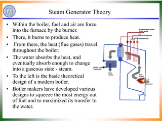
- Steam generators use heat transfer to generate steam through combustion, with combustion causing heat generation and heat transfer processes evaporating water into steam.
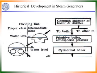
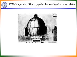
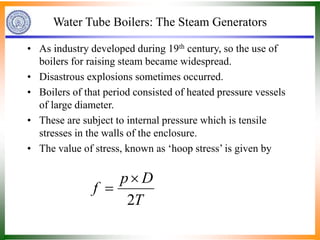
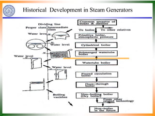
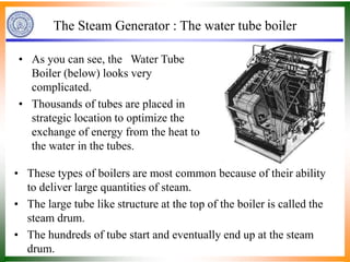
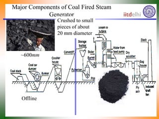
- Historically, steam generators have evolved from shell-type boilers to modern water tube boilers to efficiently transfer heat from hot gases to water.
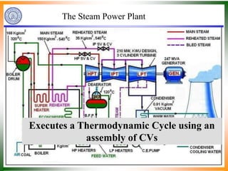
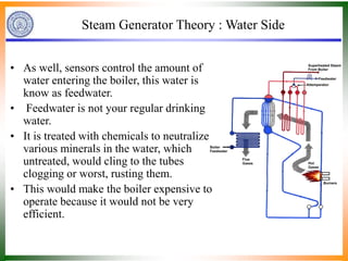
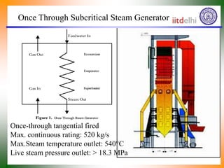
- Modern steam generators precisely control combustion and heat transfer processes to fully evaporate feedwater as it circulates through tubes, generating steam.