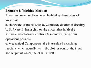
Ms. SANGEETHA B L
Assistant Professor
Department of EC
Embedded system is a combination of 3 things
 Hardware
 Software
 Mechanical Components & it is supposed to do one
specific task only.
Example 1: Washing Machine
A washing machine from an embedded systems point of
view has:
a. Hardware: Buttons, Display & buzzer, electronic circuitry.
b. Software: It has a chip on the circuit that holds the
software which drives controls & monitors the various
operations possible.
c. Mechanical Components: the internals of a washing
machine which actually wash the clothes control the input
and output of water, the chassis itself.
Example 2: Air Conditioner
An Air Conditioner from an embedded systems point of view
has:
a. Hardware: Remote, Display & buzzer, Infrared Sensors,
electronic circuitry.
b. Software: It has a chip on the circuit that holds the
software which drives controls & monitors the various
operations possible. The software monitors the external
temperature through the sensors and then releases the
coolant or suppresses it.
c. Mechanical Components: the internals of an air
conditioner the motor, the chassis, the outlet, etc
 An embedded system is designed to do a specific job only.
 Example: a washing machine can only wash clothes, an air
conditioner can control the temperature in the room in which it is
placed.
 The hardware & mechanical components will consist all the
physically visible things that are used for input, output, etc.
 An embedded system will always have a chip (either
microprocessor or microcontroller) that has the code or software
which drives the system.
An embedded system is an electronic/electromechanical system
designed to perform a specific function and is a combination
of both hardware and firmware.
HISTORY OF EMBEDDED SYSTEM
 The first recognized embedded system is the Apollo Guidance
Computer(AGC) developed by MIT lab. AGC was designed on 4K
words of ROM & 256 words of RAM.
 The clock frequency of first microchip used in AGC was 1.024 MHz.
 The computing unit of AGC consists of 11 instructions and 16 bit
word logic.
 It used 5000 ICs.
 The UI of AGC is known DSKY(display/keyboard) which resembles
a calculator type keypad with array of numerals.
 The first mass-produced embedded system was guidance computer
for the Minuteman-I missile in 1961.
 In the year 1971 Intel introduced the world's first microprocessor
chip called the 4004, was designed for use in business calculators. It
was produced by the Japanese company Busicom.
Embedded Systems vs. General computing
Systems
 The Embedded System and the General purpose computer
are at two extremes.
 The embedded system is designed to perform a specific
task whereas as per definition the general purpose computer
is meant for general use.
 It can be used for playing games, watching movies,
creating software, work on documents or spreadsheets etc.
Classification of Embedded Systems
The classification of embedded system is based on
following criteria's:
 On generation
 On complexity & performance
 On deterministic behaviour - RTS
 On triggering
Classification based on Generation
1. First generation(1G):
 Built around 8bit microprocessor & 4 bit microcontroller.
(8085 & Z80)
 Simple in hardware circuit & firmware developed.
 Examples: Digital telephone keypads, stepper motor control
units.
2. Second generation(2G):
 Built around 16-bit μp & 8/16-bit μc.
 They are more complex & powerful than 1G μp & μc.
 EOS for their operation.
 Examples: SCADA systems, Data acquisition systems.
3. Third generation(3G):
 Built around 32-bit μp & 16-bit μc.
 Concepts of application & domain specific processors/controllers like Digital
Signal Processors(DSPs), Application Specific Integrated Circuits(ASICs)
evolved.
 Instruction set complex & powerful, instruction pipelining came into picture.
 Examples: Robotics, Media, industrial process control, networking, etc.
4. Fourth generation:
 Built around 64-bit μp & 32-bit μc.
 The concept of System on Chips (SoC), Multicore Processors evolved.
 SCO-total system on a chip.
 High performance real time OS for their functioning.
 Highly complex & very powerful.
 Examples: Smart Phones, Mobile internet devices.
Classification based on complexity and
Performance
1. Small-scale:
 Simple in application need
 Performance not time-critical.
 Built around low performance & low cost 8 or 16 bit
μp/μc.
 May or may not contain an OS
 Example: an electronic toy
2. Medium-scale:
 Slightly complex in hardware & firmware requirement.
 Built around medium performance & low cost 16 or 32 bit
μp/μc or DSP.
 Usually contain embedded operating system (GP/RTOS)
 Examples: Industrial machines.
3. Large-scale:
 Highly complex hardware & firmware.
 Built around high performance 32 or 64 bit RISC μp/μc or
PLDs or Multicore Processors.
 Response is time-critical.
 RTOS for task scheduling, prioritization & management
 Examples: Mission critical applications
Classification based On deterministic behaviour
 This classification is applicable for “Real Time” systems.
 The task execution behaviour for an embedded system
may be deterministic or non-deterministic.
 Based on execution behaviour Real Time embedded
systems are divided into Hard and Soft.
Classification based On triggering
 Embedded systems which are “Reactive” in nature can be
based on triggering.
 Reactive systems can be:
Event triggered
Time triggered
APPLICATION OF EMBEDDED SYSTEM
The application areas and the products in the embedded domain are countless.
1. Consumer Electronics: Camcorders, Cameras.
2. Household appliances: Washing machine, Refrigerator.
3. Automotive industry: Anti-lock breaking system(ABS), engine control.
4. Home automation & security systems: Air conditioners, sprinklers, fire
alarms.
5. Telecom: Cellular phones, telephone switches.
6. Computer peripherals: Printers, scanners.
7. Computer networking systems: Network routers and switches.
8. Healthcare: EEG, ECG machines.
9. Banking & Retail: Automatic teller machines, point of sales.
10. Card Readers: Barcode, smart card readers.
ELEMENTS OF EMBEDDED SYSTEM
Diagrammatically an embedded system can be represented as
follows:
 ES- a single chip Microcontroller acts Master brain.
 Embedded systems are basically designed to regulate a physical
variable (such Microwave Oven) or to manipulate the state of
some devices by sending some signals to the actuators or
devices connected to the output port system (such as
temperature in Air Conditioner), in response to the input signal
provided by the end users or sensors which are connected to the
input ports.
 ES can be viewed as a reactive system.
 Examples of common user interface input devices are
keyboards, push button, switches, etc. LED’s, LCD
Piezoelectric buzzer ex of o/p devices.
 The memory of the system is responsible for holding the code
(control algorithm and other important configuration details).
 An embedded system without code (i.e. the control algorithm)
implemented memory has all the peripherals but is not
capable of making decisions depending on the situational as
well as real world changes.
 Memory for implementing the code may be present on the
processor or may be implemented as a separate chip
interfacing the processor
 In a controller based embedded system, the controller may
contain internal memory for storing code
 Such controllers are called Micro-controllers with on-chip
ROM,
 eg. Atmel AT89C51.
CORE OF THE ES
Embedded systems are domain and application specific and
are built around a central core. The core of the embedded
system falls into any of the following categories:
1. General purpose and Domain Specific Processors
1.1. Microprocessors
1.2. Microcontrollers
1.3. Digital Signal Processors
2. Application Specific Integrated Circuits. (ASIC)
3. Programmable logic devices(PLD’s)
4. Commercial off-the-shelf components (COTs)
MICROPROCESSORS
A microprocessor is a silicon chip representing a central processing unit.
A microprocessor is a dependent unit and it requires the combination of other
hardware like memory, timer unit, and interrupt controller, etc. for proper
functioning.
Developers of microprocessors.
 Intel – Intel 4004 – November 1971(4-bit).
 Intel – Intel 4040.
 Intel – Intel 8008 – April 1972.
 Intel – Intel 8080 – April 1974(8-bit).
 Motorola – Motorola 6800.
 Intel – Intel 8085 – 1976.
 Zilog - Z80 – July 1976.
Architectures used for processor design are Harvard or Von- Neumann.
RISC and CISC are the two common Instruction Set
Architectures (ISA) available for processor design.
MICROCONTROLLERS
 A microcontroller is a highly integrated chip that contains a CPU,
scratch pad RAM, special and general purpose register arrays, on
chip ROM/FLASH memory for program storage , timer and
interrupt control units and dedicated I/O ports.
 Considered as super set of microprocessors. They are cheap, cost
effective & readily available in the market.
 Texas Instrument’s TMS 1000 is considered as the world’s first
microcontroller. (1974)
 Some embedded system application require only 8 bit controllers
whereas some requiring superior performance and computational
needs demand 16/32 bit controllers.
 The instruction set of a microcontroller can be RISC or CISC.
 Microcontrollers are designed for either general purpose
application requirement (Intel 8051) or domain specific
application requirement (ASIP).
Digital Signal Processors
 DSP are powerful special purpose 8/16/32 bit microprocessor
designed to meet the computational demands and power
constraints of today’s embedded audio, video and
communication applications.
 DSP are 2 to 3 times faster than general purpose
microprocessors in signal processing applications. This is
because of the architectural difference between DSP and
general purpose microprocessors.
 DSPs implement algorithms in hardware which speeds up
the execution whereas general purpose processor implement
the algorithm in software and the speed of execution
depends primarily on the clock for the processors.
DSP includes following key units:
i. Program memory: It is a memory for storing the program required by
DSP to process the data.
ii. Data memory: It is a working memory for storing temporary variables
and data/signal to be processed.
iii. Computational engine: It performs the signal processing in accordance
with the stored program memory computational engine incorporated many
specialized arithmetic units and each of them operates simultaneously to
increase the execution speed.
It also includes multiple hardware shifters for shifting operands and saves
execution time.
iv. I/O unit: It acts as an interface between the outside world and DSP. It is
responsible for capturing signals to be processed and delivering the
processed signals.
Examples:
 Audio video signal processing, telecommunication and multimedia
applications.
 SOP(Sum of Products) calculation, convolution, FFT(Fast Fourier
Transform), DFT(Discrete Fourier Transform), etc are some of the operation
performed by DSP.
Endiannes:
 Endianness specifies the order in which the data is stored in
the memory by processor operations in a multi byte system
(Processor whose word size is greater than 1 byte).
 Based on Endiannes processors can be of two types:
1. Little Endian Processors
2. Big Endian Processors
Little-endian means lower order data byte is stored in
memory at the lowest address and the higher order data byte
at the highest address.
 For e.g, 4 byte long integer Byte3, Byte2, Byte1, Byte0 will be
stored in the memory as follows:
LITTLE ENDIAN OPERATION
Big-endian means the higher order data byte is stored in
memory at the lowest and the lower order data byte at the highest
address.
For e.g. a 4 byte integer Byte3, Byte2, Byte1, Byte0 will be stored
in the memory as follows:
BIG ENDIAN OPERATION
Application Specific Integrated Circuits (ASIC)
 ASICs is a microchip design to perform a specific and unique
applications.
 Because of using single chip for integrates several functions
there by reduces the system development cost.
 Most of the ASICs are proprietary (which having some trade
name) products, it is referred as Application Specific
Standard Products(ASSP).
 As a single chip ASIC consumes a very small area in the total
system. Thereby helps in the design of smaller system with
high capabilities or functionalities.
 The developers of such chips may not be interested in
revealing the internal detail of it .
Programmable logic devices(PLD’s)
 A PLD is an electronic component. It used to build digital
circuits which are reconfigurable.
 A logic gate has a fixed function but a PLD does not have a
defined function at the time of manufacture.
 PLDs offer customers a wide range of logic capacity,
features, speed, voltage characteristics.
 PLDs can be reconfigured to perform any number of
functions at any time.
 A variety of tools are available for the designers of PLDs
which are inexpensive and help to develop, simulate and
test the designs.
PLDs having following two major types.
1) CPLD(Complex Programmable Logic Device):
 CPLDs offer much smaller amount of logic up to 1000 gates.
2) FPGAs(Field Programmable Gate Arrays):
 It offers highest amount of performance as well as highest
logic density, the most features & high performance.
Advantages of PLDs :
1) PLDs offer customer much more flexibility during the design
cycle.
2) PLDs do not require long lead times for prototypes or
production parts because PLDs are already on a distributors
shelf and ready for shipment.
3) PLDs can be reprogrammed even after a piece of equipment
is shipped to a customer.
Commercial off-the-shelf components(COTs)
1) A Commercial off the Shelf product is one which is used 'as-is'.
2) The COTS components itself may be develop around a general purpose or
domain specific processor or an ASICs or a PLDs.
3) The major advantage of using COTS is that they are readily available in the
market, are chip and a developer can cut down his/her development time to a
great extent
4) The major drawback of using COTS components in embedded design is that
the manufacturer of the COTS component may withdraw the product or
discontinue the production of the COTS at any time if rapid change in
technology occurs.
5) Advantages of COTS:
1) Ready to use
2) Easy to integrate
3) Reduces development time
6) Disadvantages of COTS:
1) No operational or manufacturing standard (all proprietary)
2) Vendor or manufacturer may discontinue production of a particular COTS
product
Sensor
 A Sensor is used for taking Input
 It is a transducer that converts energy from one form to another
for any measurement or control purpose
 Ex. A Temperature sensor
Actuator
 Actuator is used for output.
 It is a transducer that may be either mechanical or electrical which
converts signals to corresponding physical actions.
 Ex. LED (Light Emitting Diode)
 LED is a p-n junction diode and contains a CATHODE and
ANODE
 For functioning the anode is connected to +ve end of power supply
and cathode is connected to –ve end of power supply.
 The maximum current flowing through the LED is limited by
connecting a RESISTOR in series between the power supply and
LED as shown in the figure below
SENSORS & ACTUATORS
There are two ways to interface an LED to a microprocessor/microcontroller:
1. The Anode of LED is connected to the port pin and cathode to Ground :
In this approach the port pin sources the current to the LED when it is at
logic high(ie. 1).
2. The Cathode of LED is connected to the port pin and Anode to Vcc :
In this approach the port pin sources the current to the LED when it is at
logic high (ie. 1). Here the port pin sinks the current and the LED is turned ON
when the port pin is at Logic low (ie. 0)
COMMUNICATION INTERFACE
 For any embedded system, the communication interfaces can
broadly classified into:
1. Onboard Communication Interfaces
 These are used for internal communication of the embedded
system i.e: communication between different components present
on the system.
 Common examples of onboard interfaces are:
Inter Integrated Circuit (I2C)
Serial Peripheral Interface (SPI)
Universal Asynchronous Receiver Transmitter (UART)
 1-Wire Interface
 Parallel Interface
Example :Inter Integrated Circuit (I2C)
 It is synchronous Bi-directional, half duplex , two wire serial
interface bus
 Developed by Phillips semiconductors in 1980
 It comprises of two buses :
1. Serial clock –SCL
2. Serial Data – SDA
 SCL generates synchronization clock pulses
 SDA transmits data serially across devices
 I2C is a shared bus system to which many devices can be
connected
 Devices connected by I2C can act as either master or slave
 The master device is responsible for controlling communication
by initiating/ terminating data transfer.
 Devices acting as slave wait for commands from the master and
respond to those commands.
External or Peripheral Communication
Interfaces
 These are used for external communication of the embedded
system i.e: communication of different components present on
the system with external or peripheral components/devices.
 Common examples of external interfaces are:
RS-232 C & RS-485
Universal Serial Bus (USB)
IEEE 1394 (Firewire)
Infrared (IrDA)
Bluetooth
Wi-Fi
Zig Bee
General Packet Radio Service (GPRS)
 Example: RS-232 C & RS-485
 It is wired, asynchronous, serial, full duplex
communication
 RS 232 interface was developed by EIA (Electronic
Industries Associates) In early 1960s
 RS 232 is the extension to UART for external
communications
 RS-232 logic levels use:
+3 to +25 volts to signify a "Space" (Logic 0) and
-3 to -25 volts to signify a "Mark" (logic 1).
 RS 232 supports two different types of connectors :
 DB 9 and DB 25 as shown in figure below
 RS 232 interface is a point to point communication interface and the
devices involved are called as Data Terminating Equipment (DTE)
And Data Communications Terminating Equipment (DCE)
 Embedded devices contain UART for serial transmission and
generate signal levels as per TTL/CMOS logic.
 A level translator IC (like Max 232) is used for converting the signal
lines from UART to RS 232 signal lines for communication.
 The vice versa is performed on the receiving side.
 Converter chips contain converters for both transmitters and
receivers
 RS 232 is used only for point to point connections
 It is susceptible to noise and hence is limited to short distances only
 RS 422 is another serial interface from EIA.
 It supports multipoint connections with 1 transmitter and 10
receivers.
 It supports data rates up to 100Kbps and distance up to 400 ft
 RS 485 is enhanced version of RS 422 and supports upto 32
transmitters and 32 receivers
EXTERNAL COMMUNICATION INTERFACE
 Different communication channels/buses to used by the
ES to communicate with the external world.
 RS-232 C & RS-485: (Recommended Standard)
 It is a legacy, full duplex, wired, asynchronous serial
communication interface.
 Logic 0: v/g 3V & 25V, Space
 Logic 1: v/g -3V & -25V, Mark
 2 different types of connectors: DB-9 & DB-25
 RS-232 is a point-point communication interface and the
devices involved in this are called “Data Terminal
Equipment(DTE)” and “Data Communication Equipment
(DCE)”
 For proper data transmission, RXD pin of DCE should be
connected to TXD pin of DTE and vice versa.
 RTS & CTS signals co=ordinate the communication between
DTE & DCE.
 Whenever DTE has a data to send it activates RTS line and if
the DCE is ready to accept data it activates CTS line.
 DTR signal is activated by DTE when it is ready to accept
data.
 DSR is activated by DCE when it is ready for establishing a
communication link.
 DCD control signal is used by the DCE to indicate the DTE
that a good signal is being received.
 RI is a modem specific signal line for indicating an
incoming call on the telephone line.
 RS232C supports baudrates upto 20Kbps.
 RS422 -100Kbps, 400ft, multi-drop communication
 RS485 enhanced version of RS422.
UNIVERSAL SERIAL BUS (USB)
 It is a wired high speed serial bus for data communication.
 It transmits data in packet format.
 Each data packet has a standard format.
 USB communication is a host initiated one.
 It contains a host controller which is responsible for controlling
the data communication.
 OHCI & UHCI
 Physical connection between USB peripheral device & master
device is established with a USB cable.
 It supports communication distance of up to 5mts.
 Type A connector used for upstream connection (host)
 Ex: PC’s & Laptops.
 Type B connector used for downstream connection (slave)
 Both contain 4 pins for communication.
 It uses differential signals for data transmission.
 It improves noise immunity.
 It supports different types of data transfer
 Control, bulk, Isochronous and interrupt.
 Control – to query, configure & issue commands to USB
device.
 Bulk – sending a block of data to a device, supports error
checking & correction.
 Isochronous – real time data communication.
 Interrupt – transferring small amount of data. It makes use of
polling technique.
 Low speed (1.5Mbps) USB 1.0
 Full speed (12Mbps)
 High speed (480Mbps) USB 2.0
 Super speed (4.8Gbps) USB 3.0
IEEE 1394 (FIREWARE)
 Wired isochronous high speed serial communication bus.
 HPSB, peer- peer communication & point-to-multipoint
communication allowing 63 devices to be connected.
 Serial interface, support a cable length of upto 15 feet for
interconnection.
 400-3200Mbps, differential data transfer, 3 types of
connectors
 4,6 (alpha) & 9 (beta) pin connector.
 Hardware implementation is much costlier.
IrDA - INFRARED
 Serial, half duplex, LOS based wireless technology for data
communication between devices.
 Uses infrared waves of the electromagnetic spectrum for
transmitting the data.
 Pt-pt & pt-multi pt communication, 9600-16Mbps.
 Serial IR – 9600 – 115.2Kbps
 Medium IR – 0.576Mbps – 1.152Mbps
 Fast IR – upto 4Mbps
 Very Fast IR – upto 16Mbps
 Ultra fast IR – upto 100Mbps
 Infrared LED is the IR source for transmitter and at the
receiving end a photodiode acts a receiver.
 Physical link part and protocol part.
BLUETOOTH (BT)
 Low cost, low power short range wireless technology for data
and voice communication.
 2.4GHz of the RF spectrum and uses FHSS.
 Data rate of 1Mbps & 30feet for data communication.
 Pt-pt & pt-multi pt WC.
 Piconet (max 7 slaves)
 GAP, SPP, FTP, HIDM ex bluetooth profiles
Wi-Fi
 Wireless Fidelity for networked communication of devices.
 IEEE 802.11 standard.
 Network communication and it supports IP
 Wi-Fi router.
 2.4GHz or 5GHz
OTHER SYSTEM COMPONENTS
 Reset Circuit
 Brown Out Protection Circuit – processor/controller
from unexpected program execution behaviour when
the supply v/g falls below the specified v/g. Data
corruption.
 Oscillator Unit
 Real Time Clock
 Watchdog timer
CHARACTERISTICS OF EMBEDDED
SYSTEM
 Following are some of the characteristics of an
embedded system that make it different from a general
purpose computer:
1. Application and Domain specific
 An embedded system is designed for a specific
purpose only. It will not do any other task.
Ex. A washing machine can only wash, it cannot cook
 Certain embedded systems are specific to a domain:
ex. A hearing aid is an application that belongs to the
domain of signal processing.
2. Reactive and Real time
 Certain Embedded systems are designed to react to the
events that occur in the nearby environment. These
events also occur real-time.
 Ex. An air conditioner adjusts its mechanical parts as
soon as it gets a signal from its sensors to increase or
decrease the temperature when the user operates it
using a remote control.
 An embedded system uses Sensors to take inputs and
has actuators to bring out the required functionality.
3. Operation in harsh environment
 Certain embedded systems are designed to operate in harsh
environments like very high temperature of the deserts or
very low temperature of the mountains or extreme rains.
 These embedded systems have to be capable of sustaining
the environmental conditions it is designed to operate in.
4. Distributed
 Certain embedded systems are part of a larger system and
thus form components of a distributed system.
 These components are independent of each other but have to
work together for the larger system to function properly.
 Ex. A car has many embedded systems controlled to its dash
board. Each one is an independent embedded system yet the
entire car can be said to function properly only if all the
systems work together.
5. Small size and weight
 An embedded system that is compact in size and has light
weight will be desirable or more popular than one that is
bulky and heavy.
 Ex. Currently available cell phones. The cell phones that have
the maximum features are popular but also their size and
weight is an important characteristic.
 For convenience users prefer mobile phones than phablets.
(phone + tablet pc)
6. Power concerns
 It is desirable that the power utilization and heat dissipation
of any embedded system be low.
 If more heat is dissipated then additional units like heat
sinks or cooling fans need to be added to the circuit.
 If more power is required then a battery of higher power or
more batteries need to be accommodated in the embedded
system.
QUALITY ATTRIBUTES OF
EMBEDDED SYSTEM
 These are the attributes that together form the deciding
factor about the quality of an embedded system.
 There are two types of quality attributes are:-
1. Operational Quality Attributes.
 These are attributes related to operation or functioning of an
embedded system. The way an embedded system operates affects
its overall quality.
2. Non-Operational Quality Attributes.
 These are attributes not related to operation or functioning
of an embedded system. The way an embedded system operates
affects its overall quality.
 These are the attributes that are associated with the embedded
system before it can be put in operation.
Operational Attributes
a) Response
 Response is a measure of quickness of the system.
 It gives you an idea about how fast your system is tracking the
input variables.
 Most of the embedded system demand fast response which
should be real-time.
b) Throughput
 Throughput deals with the efficiency of system.
 It can be defined as rate of production or process of a defined
process over a stated period of time.
 In case of card reader like the ones used in buses, throughput
means how much transaction the reader can perform in a
minute or hour or day.
c) Reliability
 Reliability is a measure of how much percentage you rely
upon the proper functioning of the system .
 Mean Time between failures and Mean Time To Repair are
terms used in defining system reliability.
 Mean Time between failures can be defined as the average
time the system is functioning before a failure occurs.
 Mean time to repair can be defined as the average time the
system has spent in repairs.
d) Maintainability
 Maintainability deals with support and maintenance to the
end user or a client in case of technical issues and product
failures or on the basis of a routine system checkup
 It can be classified into two types :-
1. Scheduled or Periodic Maintenance
 This is the maintenance that is required regularly after a
periodic time interval.
 Example :
 Periodic Cleaning of Air Conditioners
 Refilling of printer cartridges.
2. Maintenance to unexpected failure
 This involves the maintenance due to a sudden breakdown
in the functioning of the system.
 Example:
1. Air conditioner not powering on
2. Printer not taking paper in spite of a full paper stack
e) Security
 Confidentiality, Integrity and Availability are three corner
stones of information security.
 Confidentiality deals with protection data from
unauthorized disclosure.
 Integrity gives protection from unauthorized
modification.
 Availability gives protection from unauthorized user
 Certain Embedded systems have to make sure they
conform to the security measures.
 Ex. An Electronic Safety Deposit
f) Safety
 Safety deals with the possible damage that can happen
to the operating person and environment due to the
breakdown of an embedded system or due to the
emission of hazardous materials from the embedded
products.
 A safety analysis is a must in product engineering to
evaluate the anticipated damage and determine the
best course of action to bring down the consequence of
damages to an acceptable level.
Non Operational Attributes
a) Testability and Debug-ability
 It deals with how easily one can test his/her design,
application and by which mean he/she can test it.
 In hardware testing the peripherals and total hardware
function in designed manner
 Firmware testing is functioning in expected way
 Debug-ability is means of debugging the product as such
for figuring out the probable sources that create
unexpected behavior in the total system
b) Evolvability
 For embedded system, the qualitative attribute
“Evolvability” refer to ease with which the embedded
product can be modified to take advantage of new
firmware or hardware technology.
c) Portability
 Portability is measured of “system Independence”.
 An embedded product can be called portable if it is capable
of performing its operation as it is intended to do in various
environments irrespective of different processor and or
controller and embedded operating systems.
d) Time to prototype and market
 Time to Market is the time elapsed between the
conceptualization of a product and time at which the product
is ready for selling or use
 Product prototyping help in reducing time to market.
 Prototyping is an informal kind of rapid product
development in which important feature of the under
consider are develop.
 In order to shorten the time to prototype, make use of all
possible option like use of reuse, off the self component etc.
e) Per unit and total cost
 Cost is an important factor which needs to be carefully
monitored. Proper market study and cost benefit analysis
should be carried out before taking decision on the per unit
cost of the embedded product.
 When the product is introduced in the market, for the initial
period the sales and revenue will be low
 There won’t be much competition when the product sales
and revenue increase.
 During the maturing phase, the growth will be steady and
revenue reaches highest point and at retirement time there
will be a drop in sales volume.

Embedded systems - UNIT-1 - Mtech

  • 1.
    Ms. SANGEETHA BL Assistant Professor Department of EC
  • 2.
    Embedded system isa combination of 3 things  Hardware  Software  Mechanical Components & it is supposed to do one specific task only.
  • 3.
    Example 1: WashingMachine A washing machine from an embedded systems point of view has: a. Hardware: Buttons, Display & buzzer, electronic circuitry. b. Software: It has a chip on the circuit that holds the software which drives controls & monitors the various operations possible. c. Mechanical Components: the internals of a washing machine which actually wash the clothes control the input and output of water, the chassis itself.
  • 4.
    Example 2: AirConditioner An Air Conditioner from an embedded systems point of view has: a. Hardware: Remote, Display & buzzer, Infrared Sensors, electronic circuitry. b. Software: It has a chip on the circuit that holds the software which drives controls & monitors the various operations possible. The software monitors the external temperature through the sensors and then releases the coolant or suppresses it. c. Mechanical Components: the internals of an air conditioner the motor, the chassis, the outlet, etc
  • 5.
     An embeddedsystem is designed to do a specific job only.  Example: a washing machine can only wash clothes, an air conditioner can control the temperature in the room in which it is placed.  The hardware & mechanical components will consist all the physically visible things that are used for input, output, etc.  An embedded system will always have a chip (either microprocessor or microcontroller) that has the code or software which drives the system. An embedded system is an electronic/electromechanical system designed to perform a specific function and is a combination of both hardware and firmware.
  • 6.
    HISTORY OF EMBEDDEDSYSTEM  The first recognized embedded system is the Apollo Guidance Computer(AGC) developed by MIT lab. AGC was designed on 4K words of ROM & 256 words of RAM.  The clock frequency of first microchip used in AGC was 1.024 MHz.  The computing unit of AGC consists of 11 instructions and 16 bit word logic.  It used 5000 ICs.  The UI of AGC is known DSKY(display/keyboard) which resembles a calculator type keypad with array of numerals.  The first mass-produced embedded system was guidance computer for the Minuteman-I missile in 1961.  In the year 1971 Intel introduced the world's first microprocessor chip called the 4004, was designed for use in business calculators. It was produced by the Japanese company Busicom.
  • 7.
    Embedded Systems vs.General computing Systems  The Embedded System and the General purpose computer are at two extremes.  The embedded system is designed to perform a specific task whereas as per definition the general purpose computer is meant for general use.  It can be used for playing games, watching movies, creating software, work on documents or spreadsheets etc.
  • 9.
    Classification of EmbeddedSystems The classification of embedded system is based on following criteria's:  On generation  On complexity & performance  On deterministic behaviour - RTS  On triggering
  • 10.
    Classification based onGeneration 1. First generation(1G):  Built around 8bit microprocessor & 4 bit microcontroller. (8085 & Z80)  Simple in hardware circuit & firmware developed.  Examples: Digital telephone keypads, stepper motor control units. 2. Second generation(2G):  Built around 16-bit μp & 8/16-bit μc.  They are more complex & powerful than 1G μp & μc.  EOS for their operation.  Examples: SCADA systems, Data acquisition systems.
  • 11.
    3. Third generation(3G): Built around 32-bit μp & 16-bit μc.  Concepts of application & domain specific processors/controllers like Digital Signal Processors(DSPs), Application Specific Integrated Circuits(ASICs) evolved.  Instruction set complex & powerful, instruction pipelining came into picture.  Examples: Robotics, Media, industrial process control, networking, etc. 4. Fourth generation:  Built around 64-bit μp & 32-bit μc.  The concept of System on Chips (SoC), Multicore Processors evolved.  SCO-total system on a chip.  High performance real time OS for their functioning.  Highly complex & very powerful.  Examples: Smart Phones, Mobile internet devices.
  • 12.
    Classification based oncomplexity and Performance 1. Small-scale:  Simple in application need  Performance not time-critical.  Built around low performance & low cost 8 or 16 bit μp/μc.  May or may not contain an OS  Example: an electronic toy
  • 13.
    2. Medium-scale:  Slightlycomplex in hardware & firmware requirement.  Built around medium performance & low cost 16 or 32 bit μp/μc or DSP.  Usually contain embedded operating system (GP/RTOS)  Examples: Industrial machines. 3. Large-scale:  Highly complex hardware & firmware.  Built around high performance 32 or 64 bit RISC μp/μc or PLDs or Multicore Processors.  Response is time-critical.  RTOS for task scheduling, prioritization & management  Examples: Mission critical applications
  • 14.
    Classification based Ondeterministic behaviour  This classification is applicable for “Real Time” systems.  The task execution behaviour for an embedded system may be deterministic or non-deterministic.  Based on execution behaviour Real Time embedded systems are divided into Hard and Soft. Classification based On triggering  Embedded systems which are “Reactive” in nature can be based on triggering.  Reactive systems can be: Event triggered Time triggered
  • 15.
    APPLICATION OF EMBEDDEDSYSTEM The application areas and the products in the embedded domain are countless. 1. Consumer Electronics: Camcorders, Cameras. 2. Household appliances: Washing machine, Refrigerator. 3. Automotive industry: Anti-lock breaking system(ABS), engine control. 4. Home automation & security systems: Air conditioners, sprinklers, fire alarms. 5. Telecom: Cellular phones, telephone switches. 6. Computer peripherals: Printers, scanners. 7. Computer networking systems: Network routers and switches. 8. Healthcare: EEG, ECG machines. 9. Banking & Retail: Automatic teller machines, point of sales. 10. Card Readers: Barcode, smart card readers.
  • 16.
    ELEMENTS OF EMBEDDEDSYSTEM Diagrammatically an embedded system can be represented as follows:
  • 17.
     ES- asingle chip Microcontroller acts Master brain.  Embedded systems are basically designed to regulate a physical variable (such Microwave Oven) or to manipulate the state of some devices by sending some signals to the actuators or devices connected to the output port system (such as temperature in Air Conditioner), in response to the input signal provided by the end users or sensors which are connected to the input ports.  ES can be viewed as a reactive system.  Examples of common user interface input devices are keyboards, push button, switches, etc. LED’s, LCD Piezoelectric buzzer ex of o/p devices.  The memory of the system is responsible for holding the code (control algorithm and other important configuration details).
  • 18.
     An embeddedsystem without code (i.e. the control algorithm) implemented memory has all the peripherals but is not capable of making decisions depending on the situational as well as real world changes.  Memory for implementing the code may be present on the processor or may be implemented as a separate chip interfacing the processor  In a controller based embedded system, the controller may contain internal memory for storing code  Such controllers are called Micro-controllers with on-chip ROM,  eg. Atmel AT89C51.
  • 19.
    CORE OF THEES Embedded systems are domain and application specific and are built around a central core. The core of the embedded system falls into any of the following categories: 1. General purpose and Domain Specific Processors 1.1. Microprocessors 1.2. Microcontrollers 1.3. Digital Signal Processors 2. Application Specific Integrated Circuits. (ASIC) 3. Programmable logic devices(PLD’s) 4. Commercial off-the-shelf components (COTs)
  • 20.
    MICROPROCESSORS A microprocessor isa silicon chip representing a central processing unit. A microprocessor is a dependent unit and it requires the combination of other hardware like memory, timer unit, and interrupt controller, etc. for proper functioning. Developers of microprocessors.  Intel – Intel 4004 – November 1971(4-bit).  Intel – Intel 4040.  Intel – Intel 8008 – April 1972.  Intel – Intel 8080 – April 1974(8-bit).  Motorola – Motorola 6800.  Intel – Intel 8085 – 1976.  Zilog - Z80 – July 1976. Architectures used for processor design are Harvard or Von- Neumann.
  • 22.
    RISC and CISCare the two common Instruction Set Architectures (ISA) available for processor design.
  • 24.
    MICROCONTROLLERS  A microcontrolleris a highly integrated chip that contains a CPU, scratch pad RAM, special and general purpose register arrays, on chip ROM/FLASH memory for program storage , timer and interrupt control units and dedicated I/O ports.  Considered as super set of microprocessors. They are cheap, cost effective & readily available in the market.  Texas Instrument’s TMS 1000 is considered as the world’s first microcontroller. (1974)  Some embedded system application require only 8 bit controllers whereas some requiring superior performance and computational needs demand 16/32 bit controllers.  The instruction set of a microcontroller can be RISC or CISC.  Microcontrollers are designed for either general purpose application requirement (Intel 8051) or domain specific application requirement (ASIP).
  • 26.
    Digital Signal Processors DSP are powerful special purpose 8/16/32 bit microprocessor designed to meet the computational demands and power constraints of today’s embedded audio, video and communication applications.  DSP are 2 to 3 times faster than general purpose microprocessors in signal processing applications. This is because of the architectural difference between DSP and general purpose microprocessors.  DSPs implement algorithms in hardware which speeds up the execution whereas general purpose processor implement the algorithm in software and the speed of execution depends primarily on the clock for the processors.
  • 27.
    DSP includes followingkey units: i. Program memory: It is a memory for storing the program required by DSP to process the data. ii. Data memory: It is a working memory for storing temporary variables and data/signal to be processed. iii. Computational engine: It performs the signal processing in accordance with the stored program memory computational engine incorporated many specialized arithmetic units and each of them operates simultaneously to increase the execution speed. It also includes multiple hardware shifters for shifting operands and saves execution time. iv. I/O unit: It acts as an interface between the outside world and DSP. It is responsible for capturing signals to be processed and delivering the processed signals. Examples:  Audio video signal processing, telecommunication and multimedia applications.  SOP(Sum of Products) calculation, convolution, FFT(Fast Fourier Transform), DFT(Discrete Fourier Transform), etc are some of the operation performed by DSP.
  • 28.
    Endiannes:  Endianness specifiesthe order in which the data is stored in the memory by processor operations in a multi byte system (Processor whose word size is greater than 1 byte).  Based on Endiannes processors can be of two types: 1. Little Endian Processors 2. Big Endian Processors Little-endian means lower order data byte is stored in memory at the lowest address and the higher order data byte at the highest address.  For e.g, 4 byte long integer Byte3, Byte2, Byte1, Byte0 will be stored in the memory as follows:
  • 29.
    LITTLE ENDIAN OPERATION Big-endianmeans the higher order data byte is stored in memory at the lowest and the lower order data byte at the highest address. For e.g. a 4 byte integer Byte3, Byte2, Byte1, Byte0 will be stored in the memory as follows:
  • 30.
  • 31.
    Application Specific IntegratedCircuits (ASIC)  ASICs is a microchip design to perform a specific and unique applications.  Because of using single chip for integrates several functions there by reduces the system development cost.  Most of the ASICs are proprietary (which having some trade name) products, it is referred as Application Specific Standard Products(ASSP).  As a single chip ASIC consumes a very small area in the total system. Thereby helps in the design of smaller system with high capabilities or functionalities.  The developers of such chips may not be interested in revealing the internal detail of it .
  • 32.
    Programmable logic devices(PLD’s) A PLD is an electronic component. It used to build digital circuits which are reconfigurable.  A logic gate has a fixed function but a PLD does not have a defined function at the time of manufacture.  PLDs offer customers a wide range of logic capacity, features, speed, voltage characteristics.  PLDs can be reconfigured to perform any number of functions at any time.  A variety of tools are available for the designers of PLDs which are inexpensive and help to develop, simulate and test the designs.
  • 33.
    PLDs having followingtwo major types. 1) CPLD(Complex Programmable Logic Device):  CPLDs offer much smaller amount of logic up to 1000 gates. 2) FPGAs(Field Programmable Gate Arrays):  It offers highest amount of performance as well as highest logic density, the most features & high performance. Advantages of PLDs : 1) PLDs offer customer much more flexibility during the design cycle. 2) PLDs do not require long lead times for prototypes or production parts because PLDs are already on a distributors shelf and ready for shipment. 3) PLDs can be reprogrammed even after a piece of equipment is shipped to a customer.
  • 34.
    Commercial off-the-shelf components(COTs) 1)A Commercial off the Shelf product is one which is used 'as-is'. 2) The COTS components itself may be develop around a general purpose or domain specific processor or an ASICs or a PLDs. 3) The major advantage of using COTS is that they are readily available in the market, are chip and a developer can cut down his/her development time to a great extent 4) The major drawback of using COTS components in embedded design is that the manufacturer of the COTS component may withdraw the product or discontinue the production of the COTS at any time if rapid change in technology occurs. 5) Advantages of COTS: 1) Ready to use 2) Easy to integrate 3) Reduces development time 6) Disadvantages of COTS: 1) No operational or manufacturing standard (all proprietary) 2) Vendor or manufacturer may discontinue production of a particular COTS product
  • 35.
    Sensor  A Sensoris used for taking Input  It is a transducer that converts energy from one form to another for any measurement or control purpose  Ex. A Temperature sensor Actuator  Actuator is used for output.  It is a transducer that may be either mechanical or electrical which converts signals to corresponding physical actions.  Ex. LED (Light Emitting Diode)  LED is a p-n junction diode and contains a CATHODE and ANODE  For functioning the anode is connected to +ve end of power supply and cathode is connected to –ve end of power supply.  The maximum current flowing through the LED is limited by connecting a RESISTOR in series between the power supply and LED as shown in the figure below SENSORS & ACTUATORS
  • 36.
    There are twoways to interface an LED to a microprocessor/microcontroller: 1. The Anode of LED is connected to the port pin and cathode to Ground : In this approach the port pin sources the current to the LED when it is at logic high(ie. 1). 2. The Cathode of LED is connected to the port pin and Anode to Vcc : In this approach the port pin sources the current to the LED when it is at logic high (ie. 1). Here the port pin sinks the current and the LED is turned ON when the port pin is at Logic low (ie. 0)
  • 37.
    COMMUNICATION INTERFACE  Forany embedded system, the communication interfaces can broadly classified into: 1. Onboard Communication Interfaces  These are used for internal communication of the embedded system i.e: communication between different components present on the system.  Common examples of onboard interfaces are: Inter Integrated Circuit (I2C) Serial Peripheral Interface (SPI) Universal Asynchronous Receiver Transmitter (UART)  1-Wire Interface  Parallel Interface
  • 38.
    Example :Inter IntegratedCircuit (I2C)  It is synchronous Bi-directional, half duplex , two wire serial interface bus  Developed by Phillips semiconductors in 1980  It comprises of two buses : 1. Serial clock –SCL 2. Serial Data – SDA  SCL generates synchronization clock pulses  SDA transmits data serially across devices  I2C is a shared bus system to which many devices can be connected  Devices connected by I2C can act as either master or slave  The master device is responsible for controlling communication by initiating/ terminating data transfer.  Devices acting as slave wait for commands from the master and respond to those commands.
  • 40.
    External or PeripheralCommunication Interfaces  These are used for external communication of the embedded system i.e: communication of different components present on the system with external or peripheral components/devices.  Common examples of external interfaces are: RS-232 C & RS-485 Universal Serial Bus (USB) IEEE 1394 (Firewire) Infrared (IrDA) Bluetooth Wi-Fi Zig Bee General Packet Radio Service (GPRS)  Example: RS-232 C & RS-485
  • 41.
     It iswired, asynchronous, serial, full duplex communication  RS 232 interface was developed by EIA (Electronic Industries Associates) In early 1960s  RS 232 is the extension to UART for external communications  RS-232 logic levels use: +3 to +25 volts to signify a "Space" (Logic 0) and -3 to -25 volts to signify a "Mark" (logic 1).  RS 232 supports two different types of connectors :  DB 9 and DB 25 as shown in figure below
  • 42.
     RS 232interface is a point to point communication interface and the devices involved are called as Data Terminating Equipment (DTE) And Data Communications Terminating Equipment (DCE)  Embedded devices contain UART for serial transmission and generate signal levels as per TTL/CMOS logic.  A level translator IC (like Max 232) is used for converting the signal lines from UART to RS 232 signal lines for communication.  The vice versa is performed on the receiving side.  Converter chips contain converters for both transmitters and receivers  RS 232 is used only for point to point connections  It is susceptible to noise and hence is limited to short distances only  RS 422 is another serial interface from EIA.  It supports multipoint connections with 1 transmitter and 10 receivers.  It supports data rates up to 100Kbps and distance up to 400 ft  RS 485 is enhanced version of RS 422 and supports upto 32 transmitters and 32 receivers
  • 43.
    EXTERNAL COMMUNICATION INTERFACE Different communication channels/buses to used by the ES to communicate with the external world.  RS-232 C & RS-485: (Recommended Standard)  It is a legacy, full duplex, wired, asynchronous serial communication interface.  Logic 0: v/g 3V & 25V, Space  Logic 1: v/g -3V & -25V, Mark  2 different types of connectors: DB-9 & DB-25  RS-232 is a point-point communication interface and the devices involved in this are called “Data Terminal Equipment(DTE)” and “Data Communication Equipment (DCE)”  For proper data transmission, RXD pin of DCE should be connected to TXD pin of DTE and vice versa.
  • 44.
     RTS &CTS signals co=ordinate the communication between DTE & DCE.  Whenever DTE has a data to send it activates RTS line and if the DCE is ready to accept data it activates CTS line.  DTR signal is activated by DTE when it is ready to accept data.  DSR is activated by DCE when it is ready for establishing a communication link.  DCD control signal is used by the DCE to indicate the DTE that a good signal is being received.  RI is a modem specific signal line for indicating an incoming call on the telephone line.  RS232C supports baudrates upto 20Kbps.  RS422 -100Kbps, 400ft, multi-drop communication  RS485 enhanced version of RS422.
  • 45.
    UNIVERSAL SERIAL BUS(USB)  It is a wired high speed serial bus for data communication.  It transmits data in packet format.  Each data packet has a standard format.  USB communication is a host initiated one.  It contains a host controller which is responsible for controlling the data communication.  OHCI & UHCI  Physical connection between USB peripheral device & master device is established with a USB cable.  It supports communication distance of up to 5mts.  Type A connector used for upstream connection (host)  Ex: PC’s & Laptops.  Type B connector used for downstream connection (slave)  Both contain 4 pins for communication.
  • 46.
     It usesdifferential signals for data transmission.  It improves noise immunity.  It supports different types of data transfer  Control, bulk, Isochronous and interrupt.  Control – to query, configure & issue commands to USB device.  Bulk – sending a block of data to a device, supports error checking & correction.  Isochronous – real time data communication.  Interrupt – transferring small amount of data. It makes use of polling technique.  Low speed (1.5Mbps) USB 1.0  Full speed (12Mbps)  High speed (480Mbps) USB 2.0  Super speed (4.8Gbps) USB 3.0
  • 47.
    IEEE 1394 (FIREWARE) Wired isochronous high speed serial communication bus.  HPSB, peer- peer communication & point-to-multipoint communication allowing 63 devices to be connected.  Serial interface, support a cable length of upto 15 feet for interconnection.  400-3200Mbps, differential data transfer, 3 types of connectors  4,6 (alpha) & 9 (beta) pin connector.  Hardware implementation is much costlier.
  • 48.
    IrDA - INFRARED Serial, half duplex, LOS based wireless technology for data communication between devices.  Uses infrared waves of the electromagnetic spectrum for transmitting the data.  Pt-pt & pt-multi pt communication, 9600-16Mbps.  Serial IR – 9600 – 115.2Kbps  Medium IR – 0.576Mbps – 1.152Mbps  Fast IR – upto 4Mbps  Very Fast IR – upto 16Mbps  Ultra fast IR – upto 100Mbps  Infrared LED is the IR source for transmitter and at the receiving end a photodiode acts a receiver.  Physical link part and protocol part.
  • 49.
    BLUETOOTH (BT)  Lowcost, low power short range wireless technology for data and voice communication.  2.4GHz of the RF spectrum and uses FHSS.  Data rate of 1Mbps & 30feet for data communication.  Pt-pt & pt-multi pt WC.  Piconet (max 7 slaves)  GAP, SPP, FTP, HIDM ex bluetooth profiles
  • 50.
    Wi-Fi  Wireless Fidelityfor networked communication of devices.  IEEE 802.11 standard.  Network communication and it supports IP  Wi-Fi router.  2.4GHz or 5GHz
  • 51.
    OTHER SYSTEM COMPONENTS Reset Circuit  Brown Out Protection Circuit – processor/controller from unexpected program execution behaviour when the supply v/g falls below the specified v/g. Data corruption.  Oscillator Unit  Real Time Clock  Watchdog timer
  • 52.
    CHARACTERISTICS OF EMBEDDED SYSTEM Following are some of the characteristics of an embedded system that make it different from a general purpose computer: 1. Application and Domain specific  An embedded system is designed for a specific purpose only. It will not do any other task. Ex. A washing machine can only wash, it cannot cook  Certain embedded systems are specific to a domain: ex. A hearing aid is an application that belongs to the domain of signal processing.
  • 53.
    2. Reactive andReal time  Certain Embedded systems are designed to react to the events that occur in the nearby environment. These events also occur real-time.  Ex. An air conditioner adjusts its mechanical parts as soon as it gets a signal from its sensors to increase or decrease the temperature when the user operates it using a remote control.  An embedded system uses Sensors to take inputs and has actuators to bring out the required functionality.
  • 54.
    3. Operation inharsh environment  Certain embedded systems are designed to operate in harsh environments like very high temperature of the deserts or very low temperature of the mountains or extreme rains.  These embedded systems have to be capable of sustaining the environmental conditions it is designed to operate in. 4. Distributed  Certain embedded systems are part of a larger system and thus form components of a distributed system.  These components are independent of each other but have to work together for the larger system to function properly.  Ex. A car has many embedded systems controlled to its dash board. Each one is an independent embedded system yet the entire car can be said to function properly only if all the systems work together.
  • 55.
    5. Small sizeand weight  An embedded system that is compact in size and has light weight will be desirable or more popular than one that is bulky and heavy.  Ex. Currently available cell phones. The cell phones that have the maximum features are popular but also their size and weight is an important characteristic.  For convenience users prefer mobile phones than phablets. (phone + tablet pc) 6. Power concerns  It is desirable that the power utilization and heat dissipation of any embedded system be low.  If more heat is dissipated then additional units like heat sinks or cooling fans need to be added to the circuit.  If more power is required then a battery of higher power or more batteries need to be accommodated in the embedded system.
  • 56.
    QUALITY ATTRIBUTES OF EMBEDDEDSYSTEM  These are the attributes that together form the deciding factor about the quality of an embedded system.  There are two types of quality attributes are:- 1. Operational Quality Attributes.  These are attributes related to operation or functioning of an embedded system. The way an embedded system operates affects its overall quality. 2. Non-Operational Quality Attributes.  These are attributes not related to operation or functioning of an embedded system. The way an embedded system operates affects its overall quality.  These are the attributes that are associated with the embedded system before it can be put in operation.
  • 57.
    Operational Attributes a) Response Response is a measure of quickness of the system.  It gives you an idea about how fast your system is tracking the input variables.  Most of the embedded system demand fast response which should be real-time. b) Throughput  Throughput deals with the efficiency of system.  It can be defined as rate of production or process of a defined process over a stated period of time.  In case of card reader like the ones used in buses, throughput means how much transaction the reader can perform in a minute or hour or day.
  • 58.
    c) Reliability  Reliabilityis a measure of how much percentage you rely upon the proper functioning of the system .  Mean Time between failures and Mean Time To Repair are terms used in defining system reliability.  Mean Time between failures can be defined as the average time the system is functioning before a failure occurs.  Mean time to repair can be defined as the average time the system has spent in repairs. d) Maintainability  Maintainability deals with support and maintenance to the end user or a client in case of technical issues and product failures or on the basis of a routine system checkup  It can be classified into two types :-
  • 59.
    1. Scheduled orPeriodic Maintenance  This is the maintenance that is required regularly after a periodic time interval.  Example :  Periodic Cleaning of Air Conditioners  Refilling of printer cartridges. 2. Maintenance to unexpected failure  This involves the maintenance due to a sudden breakdown in the functioning of the system.  Example: 1. Air conditioner not powering on 2. Printer not taking paper in spite of a full paper stack
  • 60.
    e) Security  Confidentiality,Integrity and Availability are three corner stones of information security.  Confidentiality deals with protection data from unauthorized disclosure.  Integrity gives protection from unauthorized modification.  Availability gives protection from unauthorized user  Certain Embedded systems have to make sure they conform to the security measures.  Ex. An Electronic Safety Deposit
  • 61.
    f) Safety  Safetydeals with the possible damage that can happen to the operating person and environment due to the breakdown of an embedded system or due to the emission of hazardous materials from the embedded products.  A safety analysis is a must in product engineering to evaluate the anticipated damage and determine the best course of action to bring down the consequence of damages to an acceptable level.
  • 62.
    Non Operational Attributes a)Testability and Debug-ability  It deals with how easily one can test his/her design, application and by which mean he/she can test it.  In hardware testing the peripherals and total hardware function in designed manner  Firmware testing is functioning in expected way  Debug-ability is means of debugging the product as such for figuring out the probable sources that create unexpected behavior in the total system b) Evolvability  For embedded system, the qualitative attribute “Evolvability” refer to ease with which the embedded product can be modified to take advantage of new firmware or hardware technology.
  • 63.
    c) Portability  Portabilityis measured of “system Independence”.  An embedded product can be called portable if it is capable of performing its operation as it is intended to do in various environments irrespective of different processor and or controller and embedded operating systems. d) Time to prototype and market  Time to Market is the time elapsed between the conceptualization of a product and time at which the product is ready for selling or use  Product prototyping help in reducing time to market.  Prototyping is an informal kind of rapid product development in which important feature of the under consider are develop.  In order to shorten the time to prototype, make use of all possible option like use of reuse, off the self component etc.
  • 64.
    e) Per unitand total cost  Cost is an important factor which needs to be carefully monitored. Proper market study and cost benefit analysis should be carried out before taking decision on the per unit cost of the embedded product.  When the product is introduced in the market, for the initial period the sales and revenue will be low  There won’t be much competition when the product sales and revenue increase.  During the maturing phase, the growth will be steady and revenue reaches highest point and at retirement time there will be a drop in sales volume.