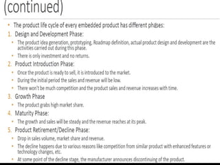
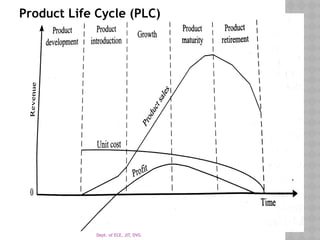
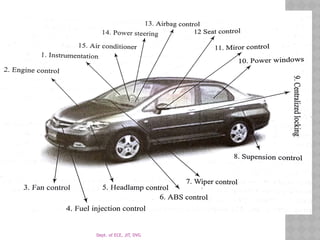
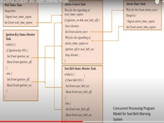
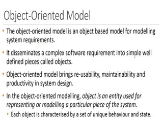
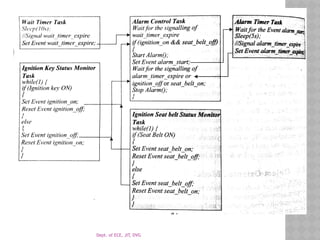
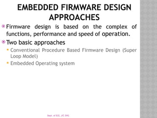
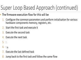
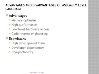
Dept. of ECE, JIT, DVG
EMBEDDED SYSTEM
DESIGN CONCEPTS
MODULE 4
Dept. of ECE, JIT, DVG
 Characteristics
 Quality attributes(Non functional aspects
that needs to be documented during
embedded system design.
Dept. of ECE, JIT, DVG
INTRODUCTION
 System can be embedded or non-embedded but
have set of characteristics.
 Functional (behave) and non-functional (quality)
forms in embedded system.
 Whatever the system while designing both
functional and non-functional are considered.
Dept. of ECE, JIT, DVG
CHARACTERISTICS OF AN EMBEDDED
SYSTEM
 All embedded has unique characteristics
 Application and domain specific.
 Reactive and Real time.
 Operates in harsh environment.
 Distributed.
 Small size and weight.
 Power concerns.
Dept. of ECE, JIT, DVG
Contd….
 Application and domain specific
 Embedded system – performs specific function and designed
to perform that exact operation
 Example
 Microwave control unit can’t work with control unit of AC
 Reactive and Real time
 Meaning of reactive- input sensors, control algorithm with
respect to input output changes
 Real-time system : system works on time critical
applications
 Should meet the deadline.
 Example: ABS, flight controlling system, missile
launch,
Dept. of ECE, JIT, DVG
CONTD.
 Operates in harsh environment
 Embedded system always won’t be in controlled
environment but also in dusty, shock, high temp. places
( Black BOX)
 System should withstand all these conditions and work
efficiently.
 Design procedure should consider these area
 Ex: LM35 for student project in high temperature area all
components should withstand it.
 Components cost will be high
Dept. of ECE, JIT, DVG
DISTRIBUTED
 It forms a large system by connected smaller
embedded system. Ex: Automatic Teller
Machine, Automatic Vending machine
 Automatic Teller Machine- contains??
 Automatic Vending machine and it contains
 Card reader ( Pre or post paid) and Vending unit.
(Coffee making machine)
 These all are independent embedded units
works in group to perform common task.
Dept. of ECE, JIT, DVG
CONTD..
 Small size and Weight
 Product details are essential for example: Mobile
 People go for small and compact device
 For embedded systems also the products should be less
in size and weight
 Power Concerns
 Power management is essential if not, heat is
generated in order to decrease need fan and extra
space is needed.
 Ultra low power devices-
Dept. of ECE, JIT, DVG
QUALITY ATTRIBUTES OF ES
 These are non-functional requirements and divided
into
 Operational Quality attributes.
 Non operational quality attributes.
 Operational Quality Attributes
 Response
 Throughput – How much cards are read from card
reader per hour( ATM machine )
 Safety-
 Reliability-
 Maintainability
 Security-
Dept. of ECE, JIT, DVG
RESPONSE
 It is the measure of quickness of system.
 How fast the system tracks the change in input
 Example: Time critical application such as safety
measure in aero-plane
 Some embedded system need apparent response
and others wont work for deadline(example
electronic toy)
Dept. of ECE, JIT, DVG
THROUGHPUT
 Defined as rate of production over a defined
time and it is measure of efficiency.
 The rate can be measured in terms of
production rate, batch production.
 Example card reader in minute how many cards it
can read .
 Measurements are based on benchmark the
device performance is measured with these
benchmark.
Dept. of ECE, JIT, DVG
CONTI.
Dept. of ECE, JIT, DVG
5
Dept. of ECE, JIT, DVG
Product Life Cycle (PLC)
Dept. of ECE, JIT, DVG
CONTI.
 Two models front load and top load
 Top load: 180 degree cloths rotation
 Front load: 360 degree cloths rotation
 Phase of washing machine(Soak, Rinse, Spin)
 1st
phase: soak the cloths with water and plunge it.
 2nd
phase: water is flushed by using liquid, powder and
rinses the clothes depending on the timer.
 3rd
phase : Inner tub uses the centrifugal force running
at RPM to send extra water from cloths called as spin
phase.
 Basic control contains timer, cycle selector mechanism,
water temperature selector, load size selector and start
button, water inlet/outlet valve.
Dept. of ECE, JIT, DVG
AUTOMOTIVE DOMAIN SPECIFIC EXAMPLES
Embedded system in automotive domain
 Inner working of Automotive embedded system
 Automotive Communication Buses
 Key players of automotive embedded market
Inner workings of Automotive embedded
system
 Application can vary from simple mirror operation to
complex ABS.
 Automotive embedded system has microcontroller, DSP or
hybrid of them and titled as ECUs (Electronic Control Unit)
 Ordinary vehicle 20-40 ECU, 75-100 in BMW
 In 1968 first embedded system used in automotive.
Dept. of ECE, JIT, DVG
TYPE OF ECU
 High speed Electronic Control units (HECUs)
 These are used in critical conditions
 Ex: fuel injection control, ABS, engine control,
electronic throttle, steering control, transmission and
central control unit.
 Low speed electronic Control Unit (LECUs)
 Used where response time is not critical
 Low cost microcontroller and processors are used.
 Ex: Audio controllers, passenger and driver locks,
window glass controller, wiper control, mirror control,
head and tail lamp etc
Dept. of ECE, JIT, DVG
AUTOMOTIVE COMMUNICATION BUSES
 Make use of serial bus for communication
 CAN Controlled Area Network (Bosch)
 It has medium speed (125 Kbps) and high speed (1Mbps)
 It event driven protocol with error handling in data
transmission. App: ABS, navigation using GPS.
 LIN Local Interconnect Network
 Single Master Multiple Slave (1, single wire low speed
( 20Kbps)
 Media- Oriented System Transport (MOST)
 Automotive video/audio interface
 Multimedia fibre optic point to point network in star, ring tapology
 MOST bus connected between Electrical optical converter
and Optical Electrical Converter
 Has physical, network, media access and application layer
Dept. of ECE, JIT, DVG
HARDWARE SOFTWARE CO-
DESIGN AND PROGRAM MODELING
 Traditional Embedded system development
 Co-design process
 Functional requirement
 System level needs
 Hardware and software trade off
 Combining all using programming language
Dept. of ECE, JIT, DVG
FUNDAMENTAL ISSUES IN HARDWARE SOFTWARE CO-
DESIGN
Development of traditional Embedded system :
 H/W requirements listed and developed by H/W
engineers,
 S/W part is decided and developed by S/W engineers,
 Both are integrated for an embedded system.
 Problem : At the market end , if the product is
good and requires huge amount of products to market
in a short time, above process takes a lot of time
because of independent development of H/W and
S/W. Hence , the designers think about H/W – S/W
co-design.
Dept. of ECE, JIT, DVG
HARDWARE AND SOFTWARE CO-DESIGN
1) First requirements from the customers are collected and those are
considered as system level requirements.
2) Hardware and software co-design is the problem statement and
issues are as follows :
 Selecting the model,
 Selecting the architecture,
 Selecting the language.
 Selecting the model: h/w and S/w co-design used to capture and
describing the system characteristics .
 Model contains objects and composition rules.
 Difficult to select the particular design and models will be keep on
changing as objective varies.
 Designer will switch from one model to another based on
requirement.
Dept. of ECE, JIT, DVG
CONTD.
 Selecting the architecture: Model gives info on system
characteristics but no information regarding how system
is manufactured.
 Architecture provides the details of it how system
implemented using components and interconnection between
them.
 Architecture are categorized into:
 Application specific architecture ---(controller architecture),
 General purpose architecture ------ (RISC,CISC),
 Parallel processing ------ (MIMD, SIMD, VLIW)
Dept. of ECE, JIT, DVG
VARIOUS ARCHITECTURE AVAILABLE
 Controller architecture- FSM using a state
register and two combinational circuit.
 Data path Architecture : Data flow graph
model.
 Finite State Machine Data path (FSMD) :
Combines Controller architecture and Data path
Architecture .
 GP Architectures : CISC & RISC.
 Parallel Processing Architecture : VLIW, MIMD,
SIMD.
Dept. of ECE, JIT, DVG
DATA PATH ARCHITECTURE
 Implemented using data flow graph model
where output is set of predefined computation
of input data.
 Data path means a definite path between
input and output
 Registers, counters, register files, memories, ports
with arithmetic unit etc.
 Data path are connected to multiple buses to
enhance the performance.
Dept. of ECE, JIT, DVG
FINITE STATE MACHINE ARCHITECTURE
 It is the combination of controller and data
path architecture.
 Controller generates the control signals and
data path process those signals
 It has two types of input output ports
 Control port to send & receive the control signals
 Input output interface to external world.
Dept. of ECE, JIT, DVG
CISC
 It has instruction set to perform complex operation.
(single instruction)
 Reading the register value, compare it and transfer
the program execution to new address all in one
single instruction.
 Reduces the memory for program but additional
microcode decoder is needed and data path is
complex.
 RISC- instruction set are simple but require multiple
risc instruction to execute complex instruction
 Data path is simple with bundle of register to store
the intermediate output.
 RISC- works on registers and supports pipeline.
Dept. of ECE, JIT, DVG
VERY LONG INSTRUCTION WORD
 It has multiple functions like ALU, multipliers
in data path.
 VLIW has one standard instruction per
functional unit in a data path.
Dept. of ECE, JIT, DVG
PARALLEL PROCESSING ARCHITECTURE
 Implements the Processing elements(PE) and
each of them has a data path (register and
local memory)
 SIMD
 Single instruction are executed in parallel with
help of PE.
 Single controller schedules and control the each
PE .
 MIMD
 Multiple instructions are executed at a given point
of time.
 It acts as the multiprocessor system.
Dept. of ECE, JIT, DVG
SELECTING THE LANGUAGE
 Programming language captures computational
model and maps it into architecture.
 To capture model C, C++, Java can be used
 Software implementation like VHDL, system C
and verilog can be used
 C++ is the good language to capture objects
 A pre-requisite to select a programming
language , it should capture the model easily.
Dept. of ECE, JIT, DVG
PARTITIONING SYSTEM REQUIREMENTS
INTO HARDWARE AND SOFTWARE
 We had learnt how to capture system
requirements for models and architecture.
 While implementation it is tough to make a
decision to opt between hardware and
software requirement.
 Various rules tradeoff are considered to opt
them.
Dept. of ECE, JIT, DVG
COMPUTATIONAL MODELS IN
EMBEDDED DESIGN.
 Data flow graph model
 State machine model
 Concurrent process model
 Sequential program model
 Object oriented model
Dept. of ECE, JIT, DVG
SEQUENTIAL PROGRAM MODEL
 In this, Functions or process are executed in
sequence.
 Data are transferred through a series of
operation with satisfied conditions.
 FSM and flow chart are used for these.
 Example for flowchart based seat belt warning
Dept. of ECE, JIT, DVG
CONCURRENT/COMMUNICATION
PROCESS MODEL
 Difference between previous and this is last
one executes sequential but concurrent
executes simultaneously.
 Example is again seat belt warning system
 Timer task for waiting 10 s ( wait timer task)
 Task for checking the ignition key status ( key
status)
 Task for checking the seat belt status.( seat belt
status)
 Task for starting and stopping the alarm (alarm
control)
 Alarm timer task for waiting 5s ( Alarm timer task)
Dept. of ECE, JIT, DVG
OBJECT ORIENTED MODEL
 It is the object based model for modelling the
system requirements using the objects.
 It ensures re-usability, maintainability and
productivity. Each object has unique behavior.
 Class provides the abstract description about
the member functions/variables and object for
accessing them.
 Use of these is abstraction, hiding and
protection.
Dept. of ECE, JIT, DVG
EMBEDDED FIRMWARE DESIGN
APPROACHES
 Firmware design is based on the complex of
functions, performance and speed of operation.
 Two basic approaches
 Conventional Procedure Based Firmware Design (Super
Loop Model)
 Embedded Operating system
Dept. of ECE, JIT, DVG
EMBEDDED OPERATING SYSTEM BASED APPROACH
 To represent user written firmware OS is needed,
which can be general purpose or real time OS
 General purpose Operating system
 Example PC with windows, Linux, Unix etc .
 Hand held devices, Portable devices, point of sale etc.
 Real time operating system- real time response
 It has real time kernel and perform, pre-emptive
multitasking, a scheduler for scheduling task, multiple
threats etc.
 RTOS allows scheduling the system resources (CPU and
memory)
 Windows CE, pSOS, VxWorks, ThreadX, MicroC/OS,
embedded linux, symbian, android etc.
Dept. of ECE, JIT, DVG
ADVANTAGES AND DISADVANTAGES OF ASSEMBLY LEVEL
LANGUAGE
 Advantages
 Memory optimize
 High performance
 Low level hardware access
 Code reverse engineering
 Drawbacks
 High development time
 Developer dependency
 Non-portability
Dept. of ECE, JIT, DVG
HIGH LEVEL LANGUAGE BASED
DEVELOPMENT
ADVANTAGES AND DISADVANTAGES
 Advantage
 Reduced Development time
 Developer independency
 Portability
 Limitation
 Cross compilers may not generate optimized code
 Low level hardware time access is more
 Tools and IDE cost is more compared to Assembly
Dept. of ECE, JIT, DVG
MIXED ASSEMBLY AND HIGH
LEVEL LANGUAGE
 Some applications need mixing of language
 Assembly with high level language
 High level with assembly
 Inline assembly programming
 Mixing high level with assembly ( C inside
assembly)
 Source code is assembly one sub-function in C
 Many reasons are there for going to assembly but
some difficult task like multiplication and
division is included in C cross-compliers
 Built in library of C like graphics using cross
compliers
Dept. of ECE, JIT, DVG
MIXING ASSEMBLY WITH HIGH LEVEL
 Source code is C assembly in some routine
 Why assembly?
 Low level hardware access
 Low level interrupt
 Memory optimize
 The function is called using the parameter passing
from C to assembly and return to C.
Dept. of ECE, JIT, DVG
C VS EMBEDDED C
 C is the well structured general purpose
register with bit manipulation with ANSI.
 Complier are used to convert C program to
target processor
 Embedded C is the subset of C with almost
the instructions runs on it
 Cross compliers are used to convert code into
machine language.
Dept. of ECE, JIT, DVG
COMPILERS VS CROSS COMPILERS
 Compiler is a software tool that converts the source
code written in a high level language to machine
level for specific running processor.
 Native compilers are used, it generates the machine
code for the same machine which it is running.
 Cross compilers are the software used in cross
platform development
 Compiler will be running in one architecture but it
generates the instructions which are suitable to run in
different architecture
Dept. of ECE, JIT, DVG
THANK YOU

Embedded system design concepts-Characteristics quality attributes

  • 1.
    Dept. of ECE,JIT, DVG EMBEDDED SYSTEM DESIGN CONCEPTS MODULE 4
  • 2.
    Dept. of ECE,JIT, DVG  Characteristics  Quality attributes(Non functional aspects that needs to be documented during embedded system design.
  • 3.
    Dept. of ECE,JIT, DVG INTRODUCTION  System can be embedded or non-embedded but have set of characteristics.  Functional (behave) and non-functional (quality) forms in embedded system.  Whatever the system while designing both functional and non-functional are considered.
  • 4.
    Dept. of ECE,JIT, DVG CHARACTERISTICS OF AN EMBEDDED SYSTEM  All embedded has unique characteristics  Application and domain specific.  Reactive and Real time.  Operates in harsh environment.  Distributed.  Small size and weight.  Power concerns.
  • 5.
    Dept. of ECE,JIT, DVG Contd….  Application and domain specific  Embedded system – performs specific function and designed to perform that exact operation  Example  Microwave control unit can’t work with control unit of AC  Reactive and Real time  Meaning of reactive- input sensors, control algorithm with respect to input output changes  Real-time system : system works on time critical applications  Should meet the deadline.  Example: ABS, flight controlling system, missile launch,
  • 6.
    Dept. of ECE,JIT, DVG CONTD.  Operates in harsh environment  Embedded system always won’t be in controlled environment but also in dusty, shock, high temp. places ( Black BOX)  System should withstand all these conditions and work efficiently.  Design procedure should consider these area  Ex: LM35 for student project in high temperature area all components should withstand it.  Components cost will be high
  • 7.
    Dept. of ECE,JIT, DVG DISTRIBUTED  It forms a large system by connected smaller embedded system. Ex: Automatic Teller Machine, Automatic Vending machine  Automatic Teller Machine- contains??  Automatic Vending machine and it contains  Card reader ( Pre or post paid) and Vending unit. (Coffee making machine)  These all are independent embedded units works in group to perform common task.
  • 8.
    Dept. of ECE,JIT, DVG CONTD..  Small size and Weight  Product details are essential for example: Mobile  People go for small and compact device  For embedded systems also the products should be less in size and weight  Power Concerns  Power management is essential if not, heat is generated in order to decrease need fan and extra space is needed.  Ultra low power devices-
  • 9.
    Dept. of ECE,JIT, DVG QUALITY ATTRIBUTES OF ES  These are non-functional requirements and divided into  Operational Quality attributes.  Non operational quality attributes.  Operational Quality Attributes  Response  Throughput – How much cards are read from card reader per hour( ATM machine )  Safety-  Reliability-  Maintainability  Security-
  • 10.
    Dept. of ECE,JIT, DVG RESPONSE  It is the measure of quickness of system.  How fast the system tracks the change in input  Example: Time critical application such as safety measure in aero-plane  Some embedded system need apparent response and others wont work for deadline(example electronic toy)
  • 11.
    Dept. of ECE,JIT, DVG THROUGHPUT  Defined as rate of production over a defined time and it is measure of efficiency.  The rate can be measured in terms of production rate, batch production.  Example card reader in minute how many cards it can read .  Measurements are based on benchmark the device performance is measured with these benchmark.
  • 12.
    Dept. of ECE,JIT, DVG CONTI.
  • 13.
    Dept. of ECE,JIT, DVG
  • 14.
    Dept. of ECE,JIT, DVG
  • 15.
    Dept. of ECE,JIT, DVG
  • 16.
    Dept. of ECE,JIT, DVG
  • 17.
    Dept. of ECE,JIT, DVG
  • 18.
    Dept. of ECE,JIT, DVG
  • 19.
    Dept. of ECE,JIT, DVG
  • 20.
    Dept. of ECE,JIT, DVG
  • 21.
    Dept. of ECE,JIT, DVG
  • 22.
    Dept. of ECE,JIT, DVG
  • 23.
    Dept. of ECE,JIT, DVG
  • 24.
    Dept. of ECE,JIT, DVG 5
  • 25.
    Dept. of ECE,JIT, DVG Product Life Cycle (PLC)
  • 26.
    Dept. of ECE,JIT, DVG
  • 27.
    Dept. of ECE,JIT, DVG
  • 28.
    Dept. of ECE,JIT, DVG
  • 29.
    Dept. of ECE,JIT, DVG
  • 30.
    Dept. of ECE,JIT, DVG CONTI.  Two models front load and top load  Top load: 180 degree cloths rotation  Front load: 360 degree cloths rotation  Phase of washing machine(Soak, Rinse, Spin)  1st phase: soak the cloths with water and plunge it.  2nd phase: water is flushed by using liquid, powder and rinses the clothes depending on the timer.  3rd phase : Inner tub uses the centrifugal force running at RPM to send extra water from cloths called as spin phase.  Basic control contains timer, cycle selector mechanism, water temperature selector, load size selector and start button, water inlet/outlet valve.
  • 31.
    Dept. of ECE,JIT, DVG
  • 32.
    Dept. of ECE,JIT, DVG AUTOMOTIVE DOMAIN SPECIFIC EXAMPLES Embedded system in automotive domain  Inner working of Automotive embedded system  Automotive Communication Buses  Key players of automotive embedded market Inner workings of Automotive embedded system  Application can vary from simple mirror operation to complex ABS.  Automotive embedded system has microcontroller, DSP or hybrid of them and titled as ECUs (Electronic Control Unit)  Ordinary vehicle 20-40 ECU, 75-100 in BMW  In 1968 first embedded system used in automotive.
  • 33.
    Dept. of ECE,JIT, DVG
  • 34.
    Dept. of ECE,JIT, DVG TYPE OF ECU  High speed Electronic Control units (HECUs)  These are used in critical conditions  Ex: fuel injection control, ABS, engine control, electronic throttle, steering control, transmission and central control unit.  Low speed electronic Control Unit (LECUs)  Used where response time is not critical  Low cost microcontroller and processors are used.  Ex: Audio controllers, passenger and driver locks, window glass controller, wiper control, mirror control, head and tail lamp etc
  • 35.
    Dept. of ECE,JIT, DVG AUTOMOTIVE COMMUNICATION BUSES  Make use of serial bus for communication  CAN Controlled Area Network (Bosch)  It has medium speed (125 Kbps) and high speed (1Mbps)  It event driven protocol with error handling in data transmission. App: ABS, navigation using GPS.  LIN Local Interconnect Network  Single Master Multiple Slave (1, single wire low speed ( 20Kbps)  Media- Oriented System Transport (MOST)  Automotive video/audio interface  Multimedia fibre optic point to point network in star, ring tapology  MOST bus connected between Electrical optical converter and Optical Electrical Converter  Has physical, network, media access and application layer
  • 36.
    Dept. of ECE,JIT, DVG HARDWARE SOFTWARE CO- DESIGN AND PROGRAM MODELING  Traditional Embedded system development  Co-design process  Functional requirement  System level needs  Hardware and software trade off  Combining all using programming language
  • 37.
    Dept. of ECE,JIT, DVG FUNDAMENTAL ISSUES IN HARDWARE SOFTWARE CO- DESIGN Development of traditional Embedded system :  H/W requirements listed and developed by H/W engineers,  S/W part is decided and developed by S/W engineers,  Both are integrated for an embedded system.  Problem : At the market end , if the product is good and requires huge amount of products to market in a short time, above process takes a lot of time because of independent development of H/W and S/W. Hence , the designers think about H/W – S/W co-design.
  • 38.
    Dept. of ECE,JIT, DVG HARDWARE AND SOFTWARE CO-DESIGN 1) First requirements from the customers are collected and those are considered as system level requirements. 2) Hardware and software co-design is the problem statement and issues are as follows :  Selecting the model,  Selecting the architecture,  Selecting the language.  Selecting the model: h/w and S/w co-design used to capture and describing the system characteristics .  Model contains objects and composition rules.  Difficult to select the particular design and models will be keep on changing as objective varies.  Designer will switch from one model to another based on requirement.
  • 39.
    Dept. of ECE,JIT, DVG CONTD.  Selecting the architecture: Model gives info on system characteristics but no information regarding how system is manufactured.  Architecture provides the details of it how system implemented using components and interconnection between them.  Architecture are categorized into:  Application specific architecture ---(controller architecture),  General purpose architecture ------ (RISC,CISC),  Parallel processing ------ (MIMD, SIMD, VLIW)
  • 40.
    Dept. of ECE,JIT, DVG VARIOUS ARCHITECTURE AVAILABLE  Controller architecture- FSM using a state register and two combinational circuit.  Data path Architecture : Data flow graph model.  Finite State Machine Data path (FSMD) : Combines Controller architecture and Data path Architecture .  GP Architectures : CISC & RISC.  Parallel Processing Architecture : VLIW, MIMD, SIMD.
  • 41.
    Dept. of ECE,JIT, DVG DATA PATH ARCHITECTURE  Implemented using data flow graph model where output is set of predefined computation of input data.  Data path means a definite path between input and output  Registers, counters, register files, memories, ports with arithmetic unit etc.  Data path are connected to multiple buses to enhance the performance.
  • 42.
    Dept. of ECE,JIT, DVG FINITE STATE MACHINE ARCHITECTURE  It is the combination of controller and data path architecture.  Controller generates the control signals and data path process those signals  It has two types of input output ports  Control port to send & receive the control signals  Input output interface to external world.
  • 43.
    Dept. of ECE,JIT, DVG CISC  It has instruction set to perform complex operation. (single instruction)  Reading the register value, compare it and transfer the program execution to new address all in one single instruction.  Reduces the memory for program but additional microcode decoder is needed and data path is complex.  RISC- instruction set are simple but require multiple risc instruction to execute complex instruction  Data path is simple with bundle of register to store the intermediate output.  RISC- works on registers and supports pipeline.
  • 44.
    Dept. of ECE,JIT, DVG VERY LONG INSTRUCTION WORD  It has multiple functions like ALU, multipliers in data path.  VLIW has one standard instruction per functional unit in a data path.
  • 45.
    Dept. of ECE,JIT, DVG PARALLEL PROCESSING ARCHITECTURE  Implements the Processing elements(PE) and each of them has a data path (register and local memory)  SIMD  Single instruction are executed in parallel with help of PE.  Single controller schedules and control the each PE .  MIMD  Multiple instructions are executed at a given point of time.  It acts as the multiprocessor system.
  • 46.
    Dept. of ECE,JIT, DVG SELECTING THE LANGUAGE  Programming language captures computational model and maps it into architecture.  To capture model C, C++, Java can be used  Software implementation like VHDL, system C and verilog can be used  C++ is the good language to capture objects  A pre-requisite to select a programming language , it should capture the model easily.
  • 47.
    Dept. of ECE,JIT, DVG PARTITIONING SYSTEM REQUIREMENTS INTO HARDWARE AND SOFTWARE  We had learnt how to capture system requirements for models and architecture.  While implementation it is tough to make a decision to opt between hardware and software requirement.  Various rules tradeoff are considered to opt them.
  • 48.
    Dept. of ECE,JIT, DVG COMPUTATIONAL MODELS IN EMBEDDED DESIGN.  Data flow graph model  State machine model  Concurrent process model  Sequential program model  Object oriented model
  • 49.
    Dept. of ECE,JIT, DVG
  • 50.
    Dept. of ECE,JIT, DVG
  • 51.
    Dept. of ECE,JIT, DVG
  • 52.
    Dept. of ECE,JIT, DVG
  • 53.
    Dept. of ECE,JIT, DVG
  • 54.
    Dept. of ECE,JIT, DVG
  • 55.
    Dept. of ECE,JIT, DVG
  • 56.
    Dept. of ECE,JIT, DVG
  • 57.
    Dept. of ECE,JIT, DVG
  • 58.
    Dept. of ECE,JIT, DVG
  • 59.
    Dept. of ECE,JIT, DVG
  • 60.
    Dept. of ECE,JIT, DVG
  • 61.
    Dept. of ECE,JIT, DVG
  • 62.
    Dept. of ECE,JIT, DVG
  • 63.
    Dept. of ECE,JIT, DVG
  • 64.
    Dept. of ECE,JIT, DVG
  • 65.
    Dept. of ECE,JIT, DVG
  • 66.
    Dept. of ECE,JIT, DVG
  • 67.
    Dept. of ECE,JIT, DVG
  • 68.
    Dept. of ECE,JIT, DVG
  • 69.
    Dept. of ECE,JIT, DVG
  • 70.
    Dept. of ECE,JIT, DVG
  • 71.
    Dept. of ECE,JIT, DVG
  • 72.
    Dept. of ECE,JIT, DVG
  • 73.
    Dept. of ECE,JIT, DVG
  • 74.
    Dept. of ECE,JIT, DVG
  • 75.
    Dept. of ECE,JIT, DVG
  • 76.
    Dept. of ECE,JIT, DVG
  • 77.
    Dept. of ECE,JIT, DVG SEQUENTIAL PROGRAM MODEL  In this, Functions or process are executed in sequence.  Data are transferred through a series of operation with satisfied conditions.  FSM and flow chart are used for these.  Example for flowchart based seat belt warning
  • 78.
    Dept. of ECE,JIT, DVG CONCURRENT/COMMUNICATION PROCESS MODEL  Difference between previous and this is last one executes sequential but concurrent executes simultaneously.  Example is again seat belt warning system  Timer task for waiting 10 s ( wait timer task)  Task for checking the ignition key status ( key status)  Task for checking the seat belt status.( seat belt status)  Task for starting and stopping the alarm (alarm control)  Alarm timer task for waiting 5s ( Alarm timer task)
  • 79.
    Dept. of ECE,JIT, DVG
  • 80.
    Dept. of ECE,JIT, DVG OBJECT ORIENTED MODEL  It is the object based model for modelling the system requirements using the objects.  It ensures re-usability, maintainability and productivity. Each object has unique behavior.  Class provides the abstract description about the member functions/variables and object for accessing them.  Use of these is abstraction, hiding and protection.
  • 81.
    Dept. of ECE,JIT, DVG
  • 82.
    Dept. of ECE,JIT, DVG
  • 83.
    Dept. of ECE,JIT, DVG EMBEDDED FIRMWARE DESIGN APPROACHES  Firmware design is based on the complex of functions, performance and speed of operation.  Two basic approaches  Conventional Procedure Based Firmware Design (Super Loop Model)  Embedded Operating system
  • 84.
    Dept. of ECE,JIT, DVG
  • 85.
    Dept. of ECE,JIT, DVG
  • 86.
    Dept. of ECE,JIT, DVG
  • 87.
    Dept. of ECE,JIT, DVG
  • 88.
    Dept. of ECE,JIT, DVG
  • 89.
    Dept. of ECE,JIT, DVG
  • 90.
    Dept. of ECE,JIT, DVG
  • 91.
    Dept. of ECE,JIT, DVG
  • 92.
    Dept. of ECE,JIT, DVG
  • 93.
    Dept. of ECE,JIT, DVG
  • 94.
    Dept. of ECE,JIT, DVG
  • 95.
    Dept. of ECE,JIT, DVG EMBEDDED OPERATING SYSTEM BASED APPROACH  To represent user written firmware OS is needed, which can be general purpose or real time OS  General purpose Operating system  Example PC with windows, Linux, Unix etc .  Hand held devices, Portable devices, point of sale etc.  Real time operating system- real time response  It has real time kernel and perform, pre-emptive multitasking, a scheduler for scheduling task, multiple threats etc.  RTOS allows scheduling the system resources (CPU and memory)  Windows CE, pSOS, VxWorks, ThreadX, MicroC/OS, embedded linux, symbian, android etc.
  • 96.
    Dept. of ECE,JIT, DVG
  • 97.
    Dept. of ECE,JIT, DVG
  • 98.
    Dept. of ECE,JIT, DVG
  • 99.
    Dept. of ECE,JIT, DVG
  • 100.
    Dept. of ECE,JIT, DVG
  • 101.
    Dept. of ECE,JIT, DVG
  • 102.
    Dept. of ECE,JIT, DVG
  • 103.
    Dept. of ECE,JIT, DVG
  • 104.
    Dept. of ECE,JIT, DVG
  • 105.
    Dept. of ECE,JIT, DVG
  • 106.
    Dept. of ECE,JIT, DVG
  • 107.
    Dept. of ECE,JIT, DVG
  • 108.
    Dept. of ECE,JIT, DVG
  • 109.
    Dept. of ECE,JIT, DVG
  • 110.
    Dept. of ECE,JIT, DVG
  • 111.
    Dept. of ECE,JIT, DVG
  • 112.
    Dept. of ECE,JIT, DVG ADVANTAGES AND DISADVANTAGES OF ASSEMBLY LEVEL LANGUAGE  Advantages  Memory optimize  High performance  Low level hardware access  Code reverse engineering  Drawbacks  High development time  Developer dependency  Non-portability
  • 113.
    Dept. of ECE,JIT, DVG HIGH LEVEL LANGUAGE BASED DEVELOPMENT ADVANTAGES AND DISADVANTAGES  Advantage  Reduced Development time  Developer independency  Portability  Limitation  Cross compilers may not generate optimized code  Low level hardware time access is more  Tools and IDE cost is more compared to Assembly
  • 114.
    Dept. of ECE,JIT, DVG MIXED ASSEMBLY AND HIGH LEVEL LANGUAGE  Some applications need mixing of language  Assembly with high level language  High level with assembly  Inline assembly programming  Mixing high level with assembly ( C inside assembly)  Source code is assembly one sub-function in C  Many reasons are there for going to assembly but some difficult task like multiplication and division is included in C cross-compliers  Built in library of C like graphics using cross compliers
  • 115.
    Dept. of ECE,JIT, DVG MIXING ASSEMBLY WITH HIGH LEVEL  Source code is C assembly in some routine  Why assembly?  Low level hardware access  Low level interrupt  Memory optimize  The function is called using the parameter passing from C to assembly and return to C.
  • 116.
    Dept. of ECE,JIT, DVG C VS EMBEDDED C  C is the well structured general purpose register with bit manipulation with ANSI.  Complier are used to convert C program to target processor  Embedded C is the subset of C with almost the instructions runs on it  Cross compliers are used to convert code into machine language.
  • 117.
    Dept. of ECE,JIT, DVG COMPILERS VS CROSS COMPILERS  Compiler is a software tool that converts the source code written in a high level language to machine level for specific running processor.  Native compilers are used, it generates the machine code for the same machine which it is running.  Cross compilers are the software used in cross platform development  Compiler will be running in one architecture but it generates the instructions which are suitable to run in different architecture
  • 118.
    Dept. of ECE,JIT, DVG THANK YOU

Editor's Notes

  • #3 System can be embedded or non-embedded but have set of characteristics which describe the system.
  • #4 Unlike general purpose computing system all the embedded system has unique characteristics.
  • #5 Embedded system has the constant interaction with real world through sensors and user defined input devices connected to input port. Reactive – it produces the output in response to change in input / sensors. Embedded can be real or non-real time ex: ABS and Toys respectively.
  • #6 System shouldn’t undergo corrosion, power flucation, aging
  • #7 ATM has Card reader, identify user using magnetic strip Transmission unit, GPS Counting unit and dispatcher Printer section to print the summary of transaction. SCADA (Supervisory Control and Data Acquisition).
  • #8 Less power more battery life more market
  • #9 Response – how fast the system responds. Ex: aero application speed response. Electronic toy lesser speed Throughput- Rate of production over a definite time and it is measure of efficiency. Safety- designed system should not harm environment. If radio active material is there after accident also it should not come outside Maintainability - It is support and maintenance to the client which include technical and product failure. Security- security to unauthenticated access.
  • #12 MTBF- Mean time between fault MTTR- Mean time to Repair, MTBF – how often the system fails MTTR – in how much time it got repaired
  • #13 Avalibility = MTBF / MTBF+MTTR
  • #14 Availability- all data are available if user name and password is matched in LAB computers Integrity – C drive data can be viewable can’t be modified Confidentiality – Administrator login required to add or remove the program.
  • #17 Testing – hardware test- sensors are working or not Software test- software is working or not and list it DEBUG- provide solution to the list produced from test department Evolve – changes in existing system to new system to meet customer demands Portability is easy for C programming
  • #28 1st WKT embedded system has sensors, actuators, interface unit (keyboard, display unit) and all these are present on washing machine. Some are visible are some sensors are not visible. Agitator – middle component to turn cloths
  • #32 1st phase – top load cloths 180 front load 360 rotation 2nd phase- water goes out and spinning (centrifugal force) of washing machine occurs. After 2nd phase water is concentrated by holes and pushed outside through outlet value. Control system are provided to increase/decrease the time of soak,rinse,spin – show iin figure – light medium heavy.
  • #34 Embedded system is in almost all field in which telecom and automotive holds the big market sale.
  • #37 Medium speed – ISO 11519 class b high speed- ISO11898 class C
  • #39 Model gives the information about the system characteristics.
  • #41 For example are controller and datapath architecture. CISC, RISK, Very long instruction word computing, SIMD, MIMD
  • #42 Finite state machine model State register is for storing the present and combinational implements the logic of next state and output
  • #43 . Ports with arithmetic unit are connected in parallel with pipeline.
  • #46 Instruction level parallelism Successor of RISK
  • #47 PE in MIMD communicates through shared memory and message passing.
  • #59 State – current situations Event- input to state; stimulate for state transition Transitions- movement from one state to another Action- perform activity of the state machine.
  • #83 Public, private functions and variables used to access them Derived class from parents called as inheritance. Abstraction is providing necessary information and hiding the unnecessary Data hiding is broad class of abstraction
  • #87 Super loop based approach. – execute task one after the other after executing last task switch to 1st task
  • #88 Drawbacks- 1. one task fails all fails Hangs in one program the system will be inside that loop which leads to total failure of the system
  • #100 General purpose operating system- OS will be present, above it the applications are build and executed. Realtime operating system- it is used when products demands the real time responses and work for deadlines
  • #117 Advantage Developer with optimum knowledge on architecture he can write the effective code with lesser area hence cost on memory also decreases. Total system performance has increases with optimized code Low level interrupt, system components, OS based access make use of assembly The converting of HEX into the assembly is easier using dis-assembler.
  • #121 American National Standards