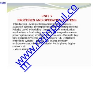
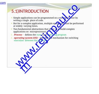
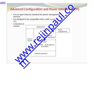
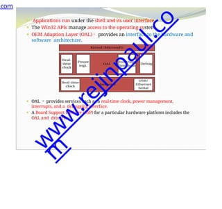
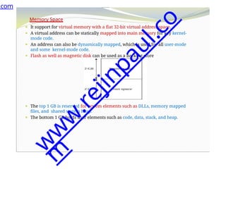
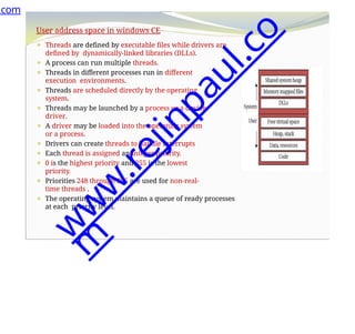
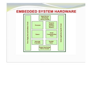
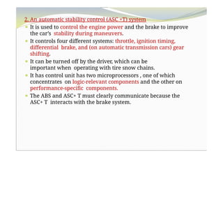
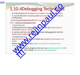
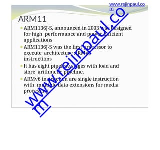
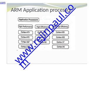
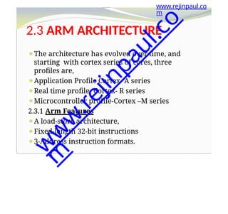
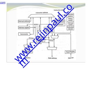
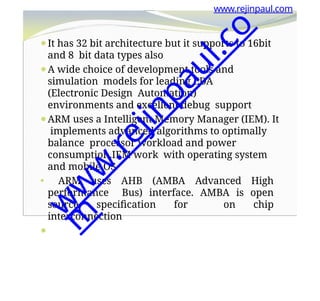
The document outlines a course on embedded and real-time systems, focusing on embedded system design, ARM processor architecture, embedded programming, and real-time operating systems. It covers the introduction to embedded systems, components, programming models, and challenges in embedded computing design, along with practical applications and performance optimization. Lastly, it includes suggested textbooks and references for further reading.


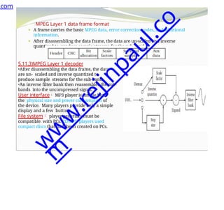
![www.rejinpaul.com
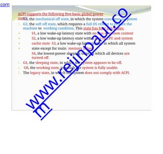
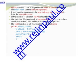
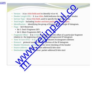
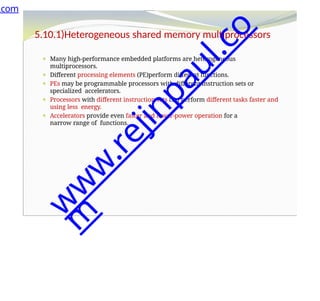
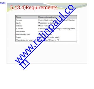
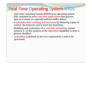
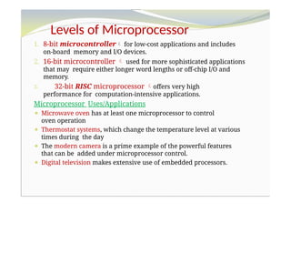
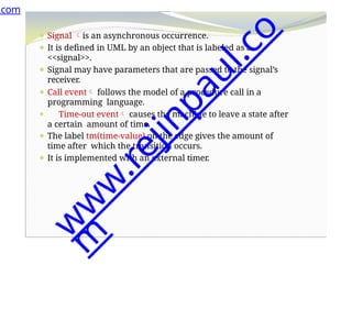
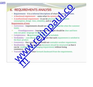
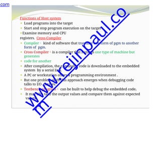
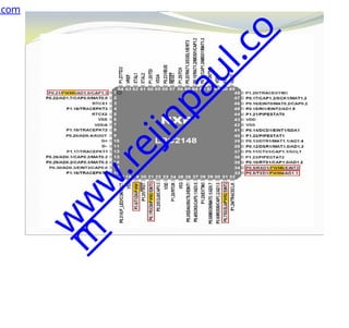
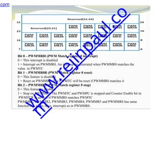
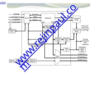
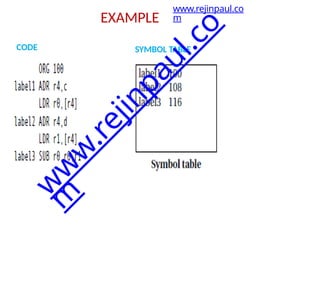
⚫INTNMI- Non-maskable interrupt
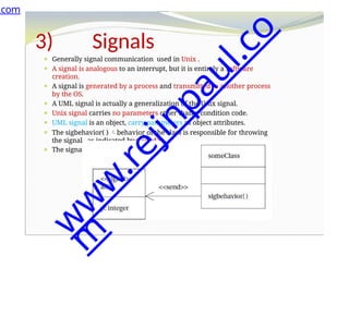
⚫INTISR[239:0]- External interrupt signals
⚫SLEEPING- Indicates that the Cortex-M3 clock
can be stopped.
⚫SLEEPDEEP - Indicates that the Cortex-M3 clock
can be stopped
⚫WIC - Wake-up Interrupt Controller
⚫NVIC- Nested Vectored Interrupt Controller
⚫ETM- Embedded Trace Macrocell
⚫The ETM is an optional debug component that
enables reconstruction of program execution.
The ETM is designed to be a high-speed, low-
power debug tool that only supports instruction
trace
w
w
w
.
r
e
j
i
n
p
a
u
l
.
c
o
m](https://image.slidesharecdn.com/ec8791-embeddedandrealtimesystemsunitsnotes1-240812040420-6fac6ffa/85/EC8791-Embedded-and-Real-Time-Systems-UNITS-NOTES-1-pptx-215-320.jpg)

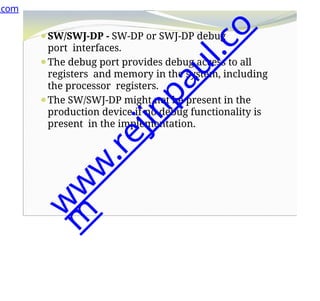
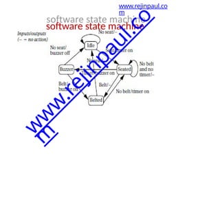

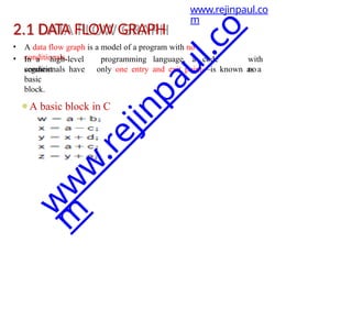

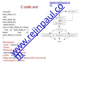
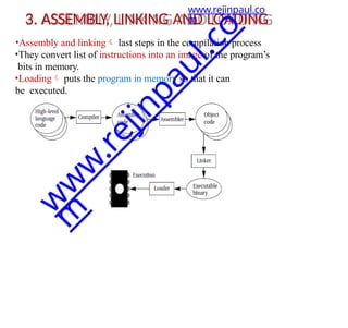


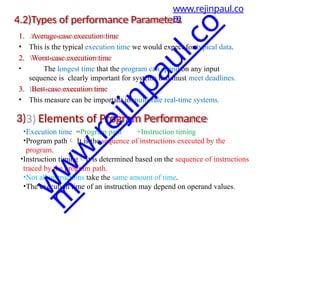
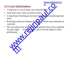
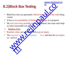
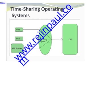
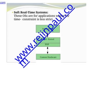
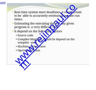
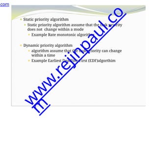
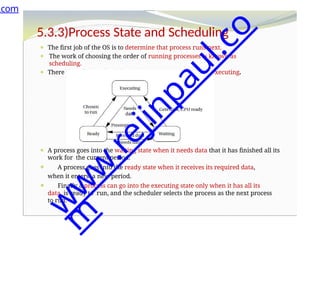
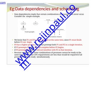
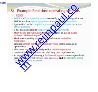
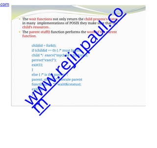
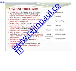
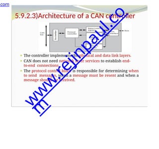
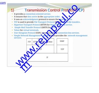
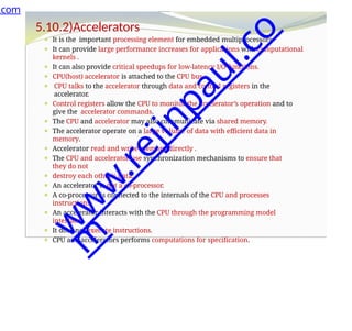
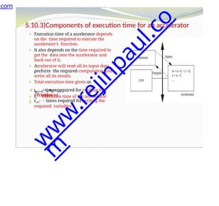
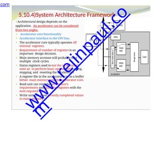
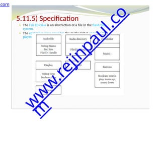
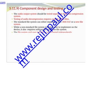
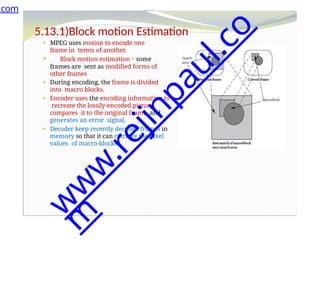
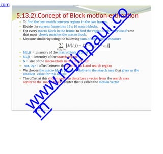
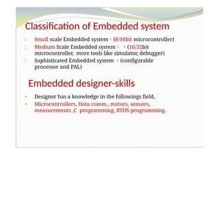
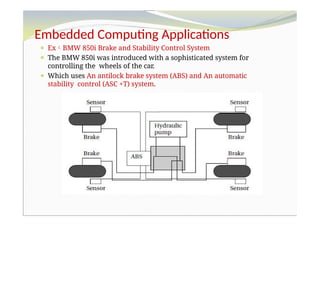
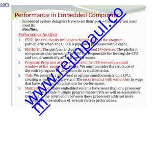
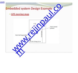
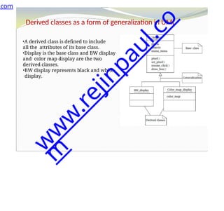
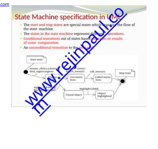
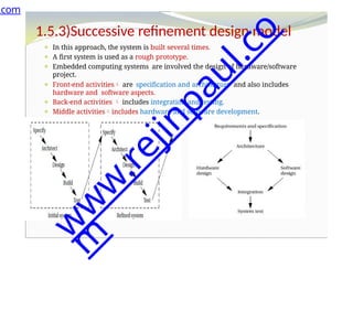
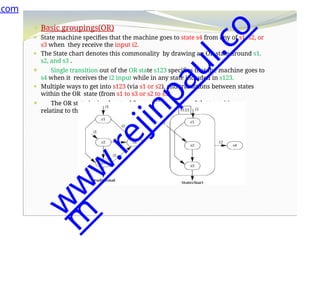
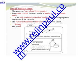
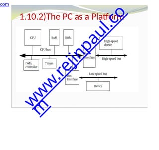
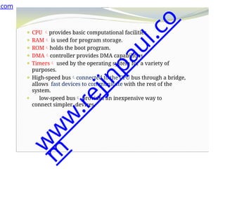
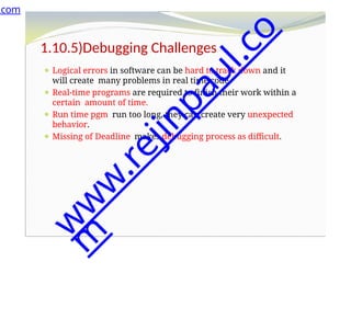
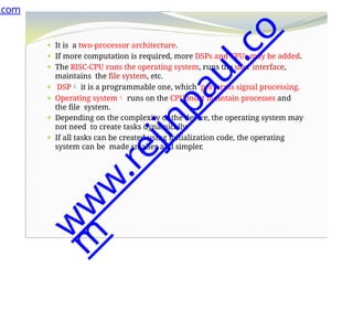
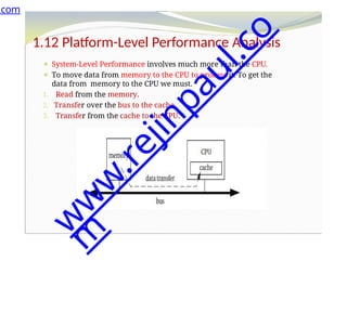
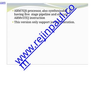
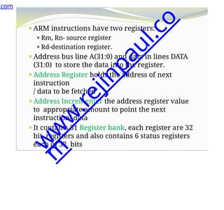
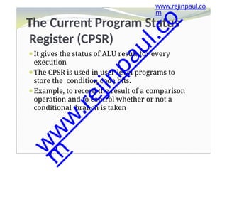
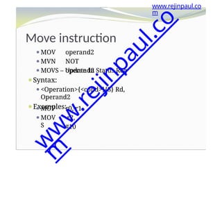
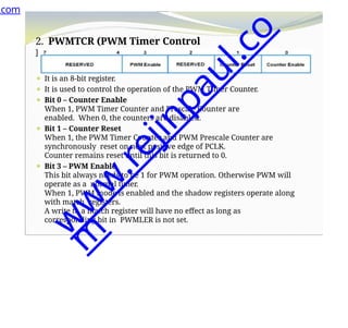
![5. SOFTWARE PERFORMANCE OPTIMIZATION
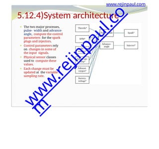
1) Loop Optimizations-Loops are important targets for optimization
because programs with loops tend to spend a lot of time
executing those loops.
• Code motion
• Induction variable elimination
• Strength reduction
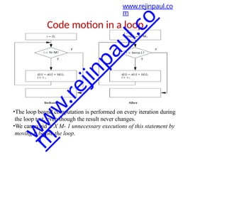
Code motion
• It can move
unnecessary code
out of a loop.
• If a computation’s
result does not
depend on
operations
performed
in the loop
body,thenwe can
safely move it out
of the loop.
for (i = 0; i < N*M;
i++)
{
z[i] = a[i] + b[i];
}
www.rejinpaul.co
m
w
w
w
.
r
e
j
i
n
p
a
u
l
.
c
o
m](https://image.slidesharecdn.com/ec8791-embeddedandrealtimesystemsunitsnotes1-240812040420-6fac6ffa/85/EC8791-Embedded-and-Real-Time-Systems-UNITS-NOTES-1-pptx-245-320.jpg)
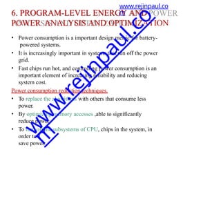
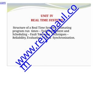
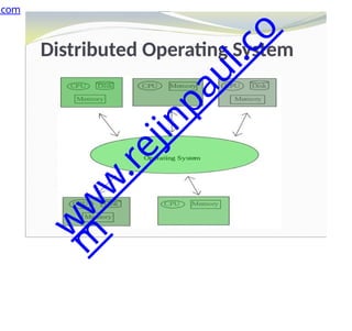
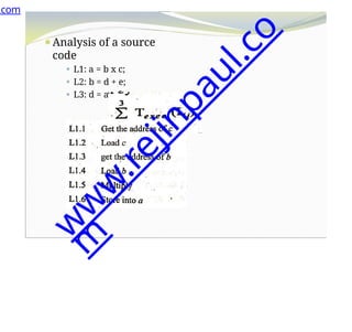
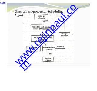
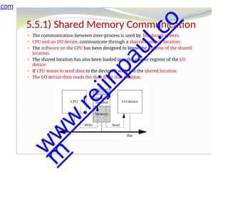
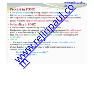
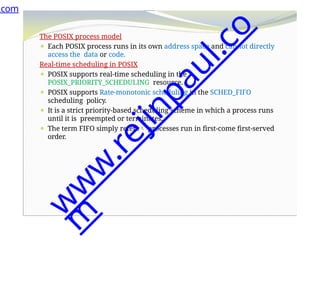
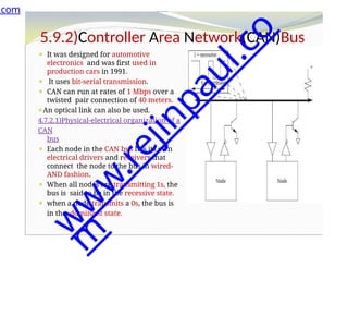
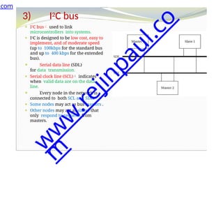
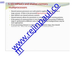
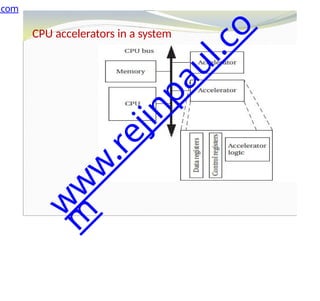
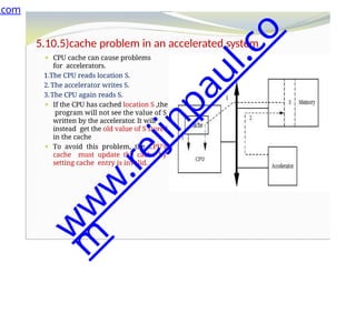
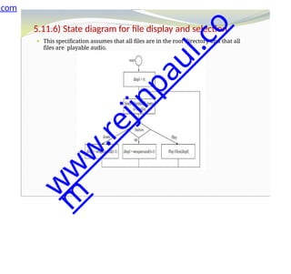
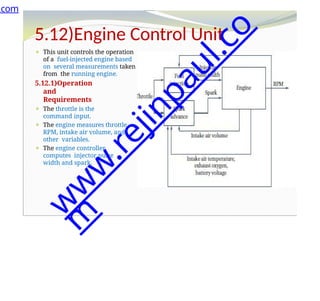
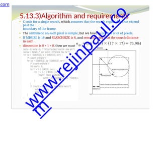
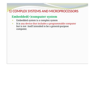
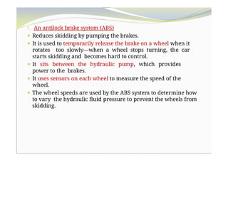
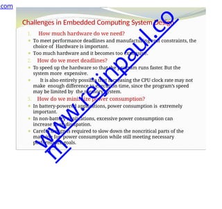
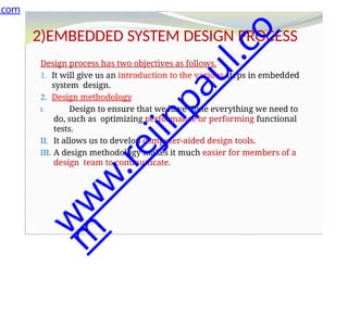
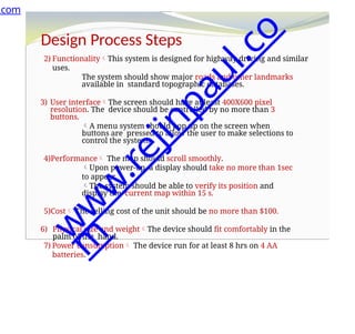
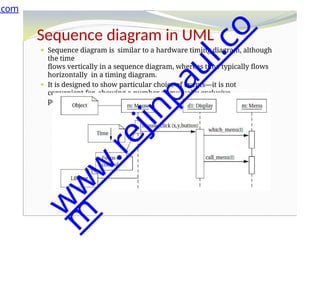
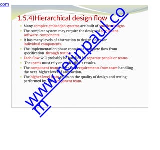
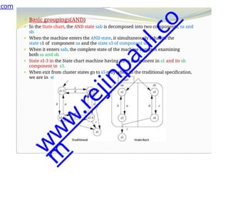
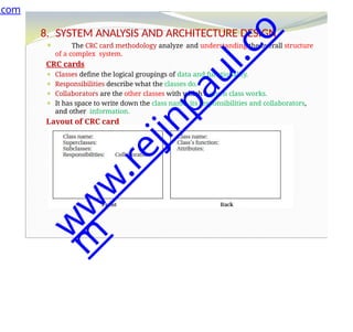
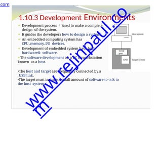
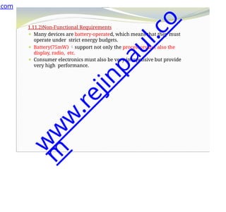
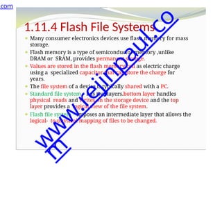
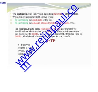
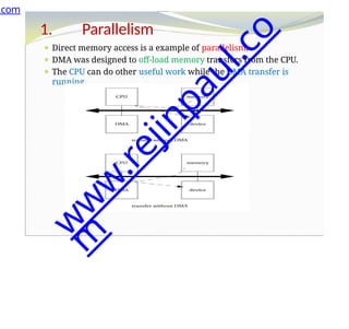
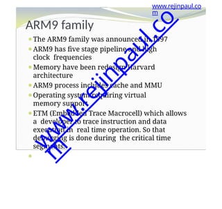
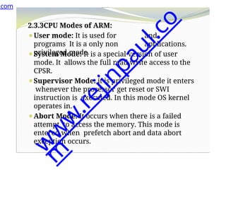
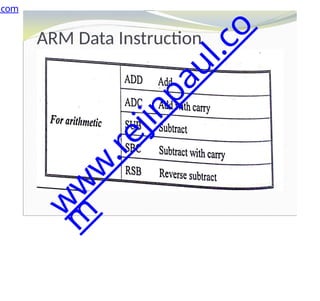
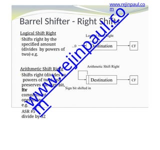
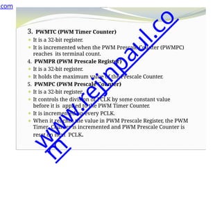
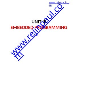
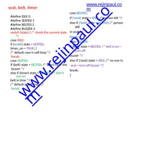
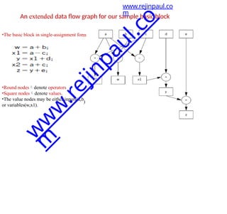
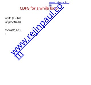
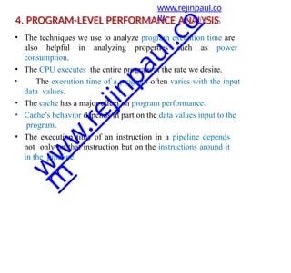
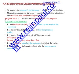
![• It is a variable whose value is derived from the loop iteration variable’s value.
• The compiler often introduces induction variables to help it implement the
loop.
• Properly transformed able to eliminate some variables and apply strength
reduction to others.
• A nested loop is a good example of the use of induction variables.
for (i = 0; i < N; i++)
for (j = 0; j < M; j++)
z[i][j] = b[i][j];
• The compiler uses induction variables to help it address the arrays. Let us
rewrite the loop in C using induction variables and pointers
for (i = 0; i < N; i++)
for (j = 0; j < M; j++) {
zbinduct = i*M + j;
*(zptr + zbinduct) =
*(bptr + zbinduct);
}
www.rejinpaul.co
m
Induction variable elimination
w
w
w
.
r
e
j
i
n
p
a
u
l
.
c
o
m](https://image.slidesharecdn.com/ec8791-embeddedandrealtimesystemsunitsnotes1-240812040420-6fac6ffa/85/EC8791-Embedded-and-Real-Time-Systems-UNITS-NOTES-1-pptx-247-320.jpg)