Embedded Networking - Serial Bus Communication Protocols – I2C Bus
1.
1
Embedded Networking
Serial BusCommunication
Protocols – I2C Bus
References:
1. Marilyn Wolf, “Computers as Components - Principles of Embedded Computing System Design”, Third Edition, Morgan
Kaufmann Publisher
2. Rajkamal, ‘Embedded System-Architecture, Programming, Design’, McGraw Hill
3. Shibu. K.V, “Introduction to Embedded Systems”, Tata Mcgraw Hill
REAL TIME CONCEPTSFOR EMBEDDED SYSTEMS
7/15/2025 8
The I2C Bus
Structure of an I2C bus system
Electrical interface to the I2C bus
Format of an I2C address transmission
State transition graph for an I2C bus master
Typical bus transactions on the I2C bus
Transmitting a byte on the I2C bus
An I2C interface in a microcontroller
9.
REAL TIME CONCEPTSFOR EMBEDDED SYSTEMS
7/15/2025 9
Several interconnect networks have been developed especially for
distributed embedded computing:
■ The I2C bus is used in microcontroller-based systems.
■ The Controller Area Network (CAN) bus was developed for automotive
electronics.
It provides megabit rates and can handle large numbers of devices.
■ Ethernet and variations of standard Ethernet are used for a variety of
control applications.
10.
REAL TIME CONCEPTSFOR EMBEDDED SYSTEMS
7/15/2025 10
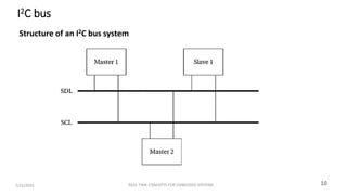
I2C bus
Structure of an I2C bus system
11.
I2C bus
●I2C busused to link microcontrollers into systems.
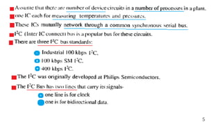
●I2C is designed to be low cost, easy to implement, and of moderate
speed (up to 100kbps for the standard bus and up to 400 kbps for
the extended bus).
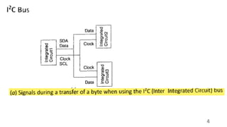
● Serial data line (SDL) for data transmission.
●Serial clock line (SCL) indicates when valid data are on the data
line.
● Every node in the network is connected to both SCL and SDL.
●Some nodes may act as bus masters .
●Other nodes may act as slaves that only respond to requests from
masters.
12.
REAL TIME CONCEPTSFOR EMBEDDED SYSTEMS
7/15/2025 12
Electrical interface to the I2C bus
13.
Electrical interface tothe I2C bus
●Both bus lines are defined by an electrical signal.
●Both bus signals use open collector/open drain circuits.
●The open collector/open drain circuitry allows a slave device to stretch a clock signal during
a read.
●The master is responsible forgenerating the SCL clock.
●The slave can stretch the low period of the clock.
●It is a multi master bus so different devices may act as the master at various times.
●Masterdrives both SCL and SDL when it is sending data.
●When the bus is idle, both SCL and SDL remain high.
●When two devices try to drive either SCL or SDL , the open collector/open drain circuitry
prevents errors.
●Each masterdevice make sure that it is not interfering with another message.
14.
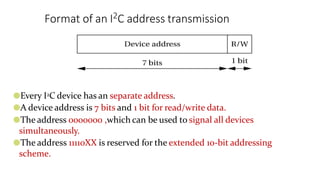
Format of anI2C address transmission
●Every I2C device has an separate address.
●A device address is 7 bits and 1 bit for read/write data.
●The address 0000000 ,which can be used to signal all devices
simultaneously.
●The address 11110XX is reserved for the extended 10-bit addressing
scheme.
15.
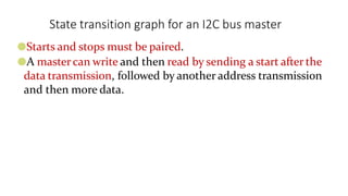
State transition graphfor an I2C bus master
●Starts and stops must be paired.
●A mastercan write and then read by sending a start after the
data transmission, followed by another address transmission
and then more data.
REAL TIME CONCEPTSFOR EMBEDDED SYSTEMS
7/15/2025 17
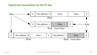
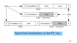
Typical bus transactions on the I2C bus
18.
Bus transactions onthe I2C bus
●When a masterwants to write a slave, it transmits the slave’s address followed
by the data.
●When a mastersend a read requestwith the slave’saddress and the slave
transmit the data.
●Transmission address has 7-bit and 1 bit for data direction.( 0 forwriting
from the master to the slave and 1 for reading from the slave to the master)
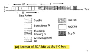
●A bus transaction is initiated by a start signal and completed with an end
signal.
●A start is signaled by leaving the SCL high and sending a 1 to 0 transition on
SDL.
●A stop is signaled by setting the SCL high and sending a 0 to 1 transition on
SDL.
19.
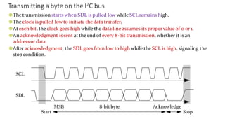
Transmitting a byteon the I2C bus
●The transmission starts when SDL is pulled low while SCL remains high.
●The clock is pulled low to initiate the data transfer.
●At each bit, the clock goes high while the data line assumes its propervalue of 0 or 1.
●An acknowledgment is sent at the end of every 8-bit transmission, whether it is an
address or data.
●Afteracknowledgment, the SDL goes from low to high while the SCL is high, signaling the
stop condition.
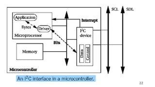
I2C interface ina microcontroller
●System has a 1-bit hardware interface with routines for byte-level
functions.
●I2C device used to generates the clock and data.
●Application code calls routines to send an address, data byte, and also
generates the SCL , SDL and acknowledges.
●Timers is used to control the length of bits on the bus.
●When Interrupts used in master mode, polled I/O may be acceptable.
●If no other pending tasks can be performed, because masters initiate their
own transfers.