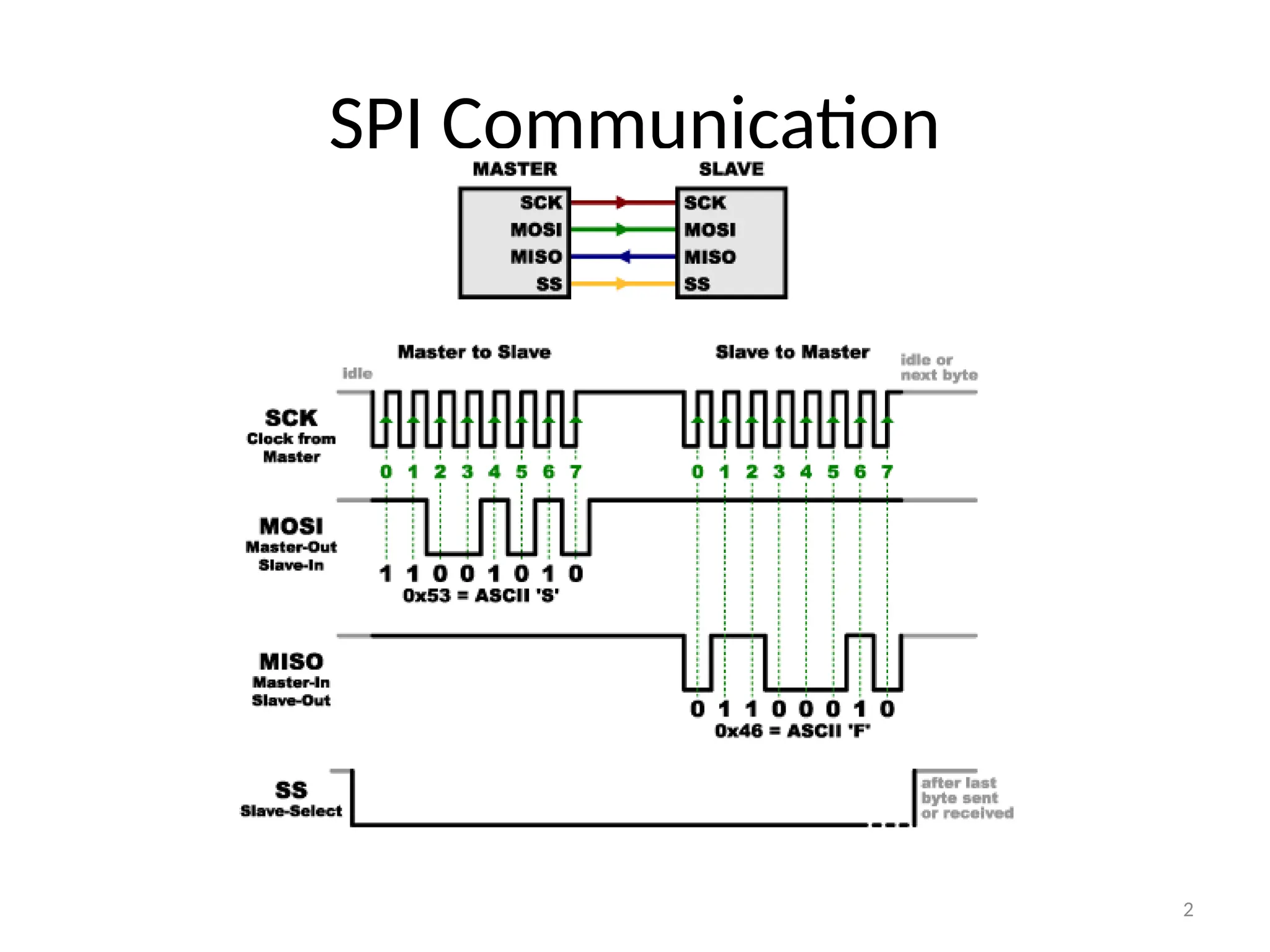
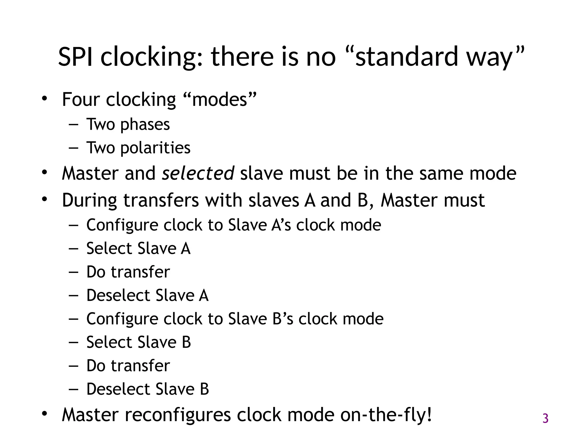
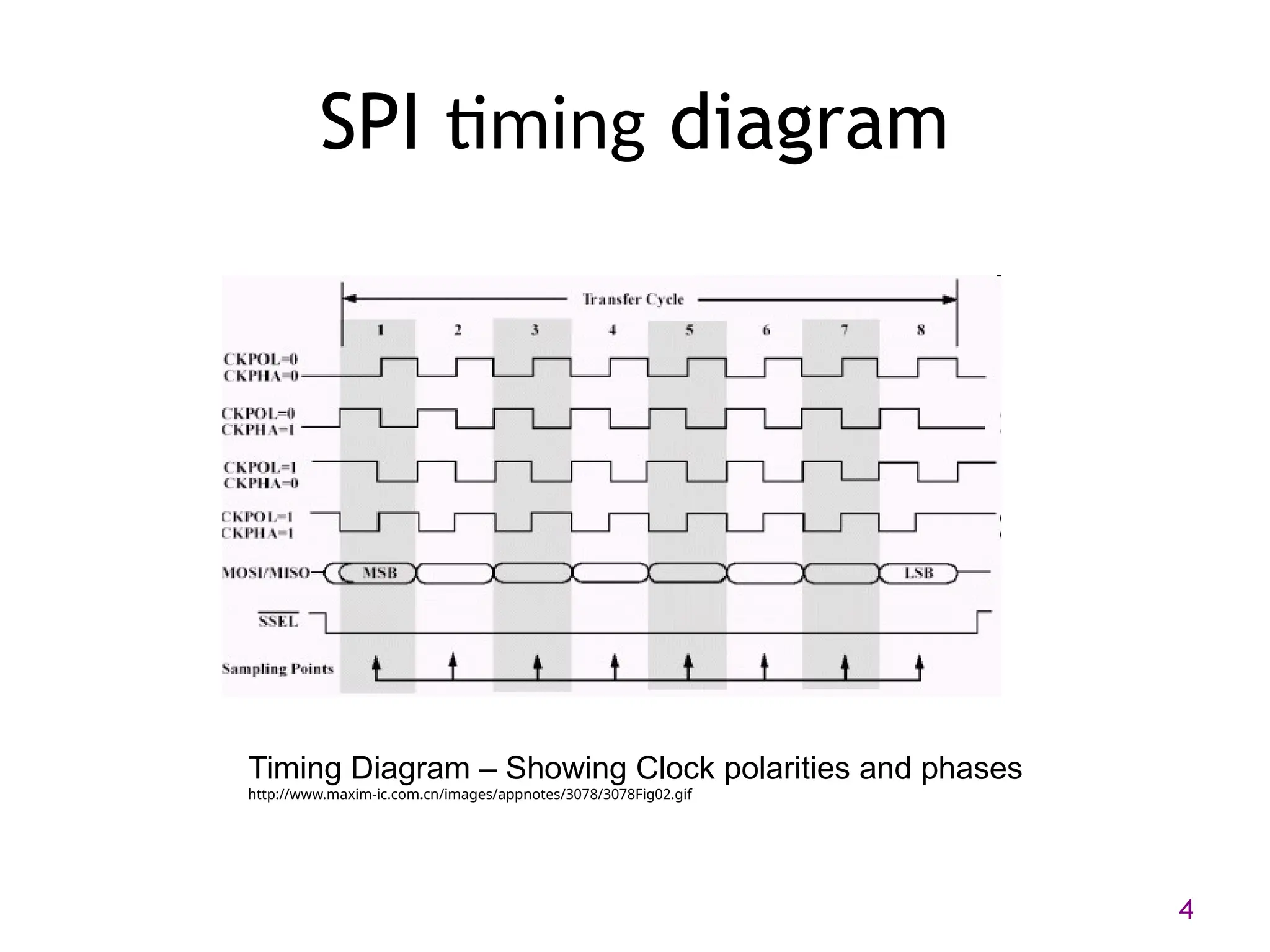
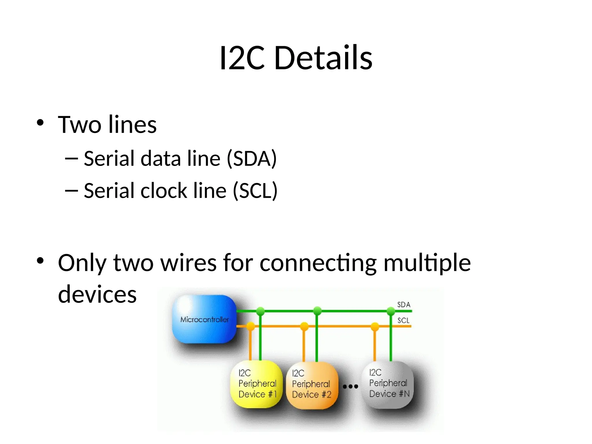
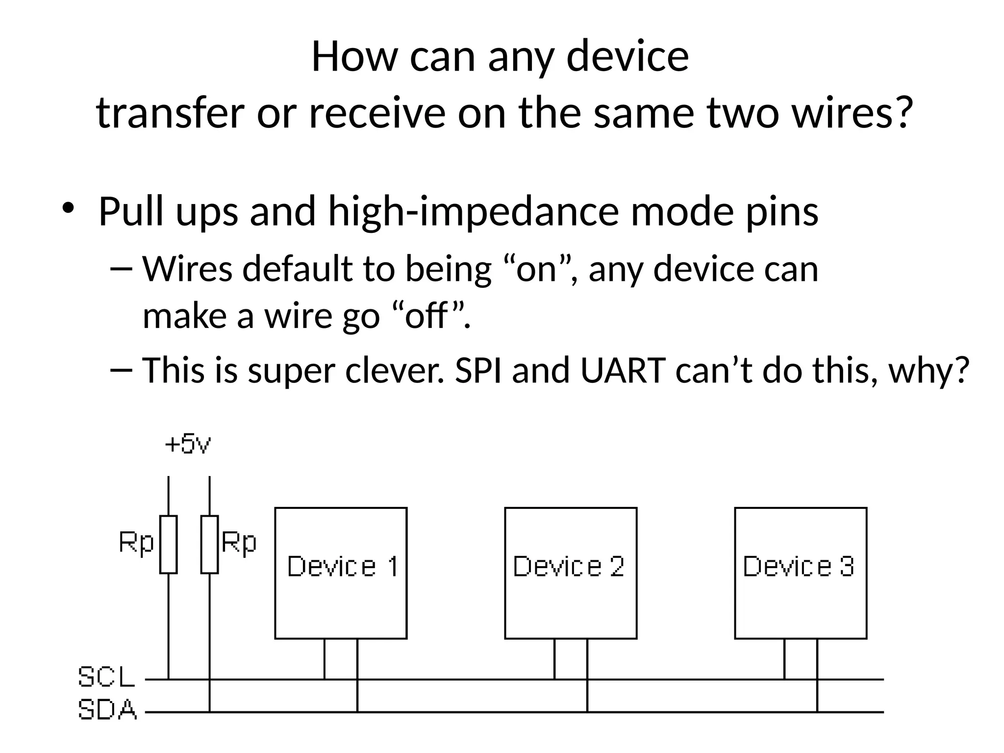
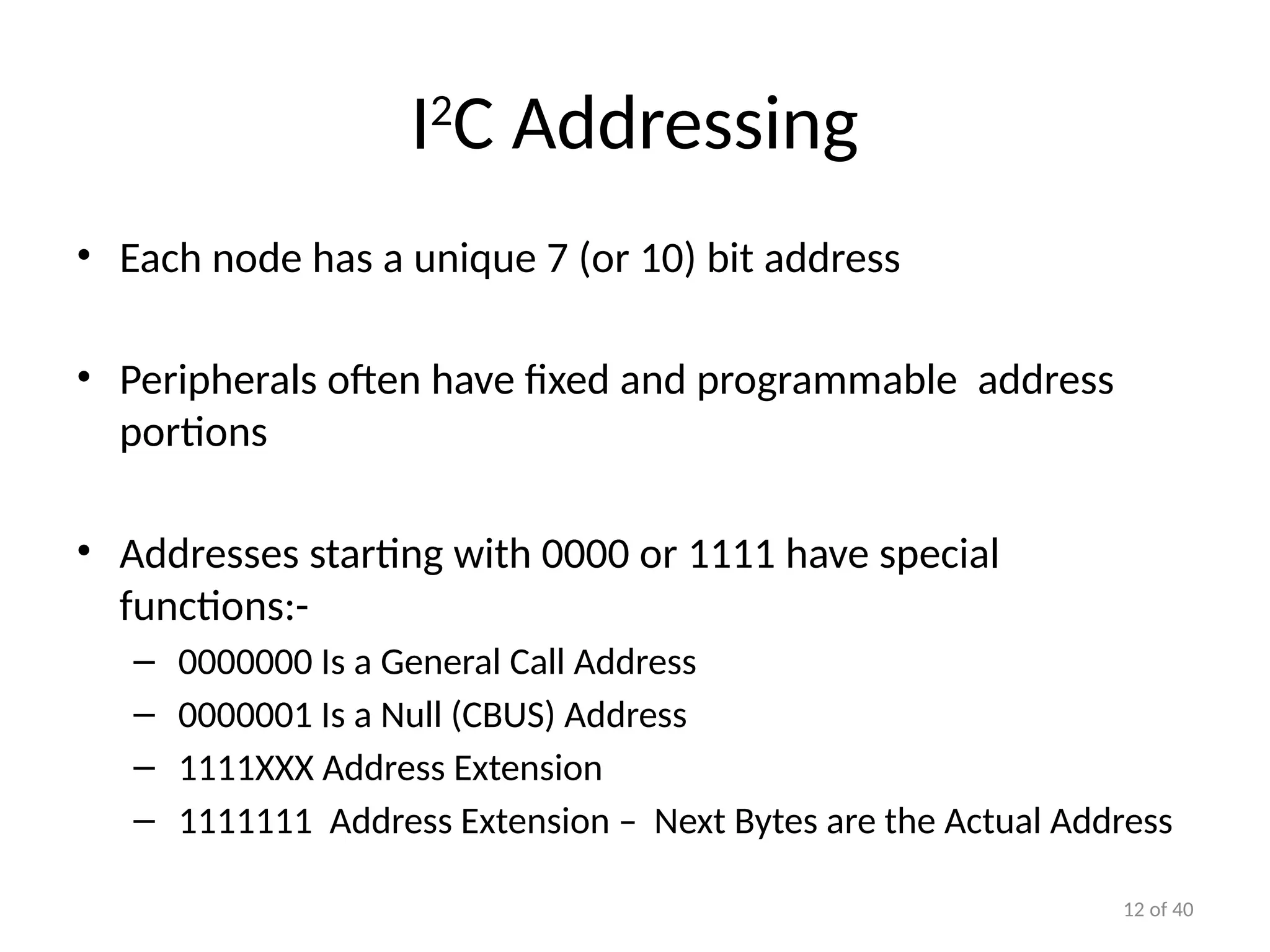
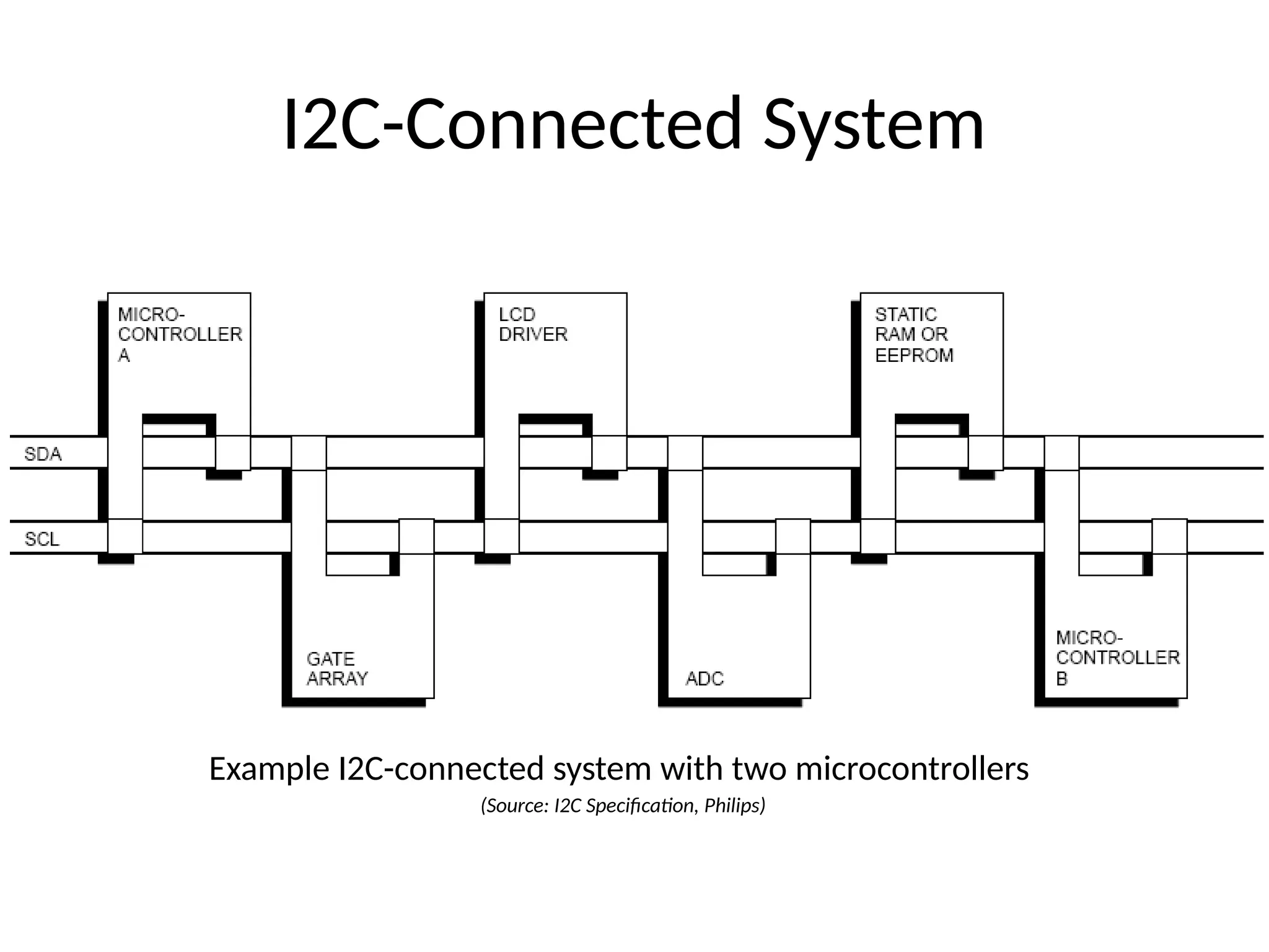
Wireless Embedded Systems
Aaron Schulman
CSE190 Winter 2020
Lecture 7
SPI and I2C
2
SPI Communication
3
SPI clocking: there is no “standard way”
• Four clocking “modes”
– Two phases
– Two polarities
• Master and selected slave must be in the same mode
• During transfers with slaves A and B, Master must
– Configure clock to Slave A’s clock mode
– Select Slave A
– Do transfer
– Deselect Slave A
– Configure clock to Slave B’s clock mode
– Select Slave B
– Do transfer
– Deselect Slave B
• Master reconfigures clock mode on-the-fly!
4
SPI timing diagram
Timing Diagram – Showing Clock polarities and phases
http://www.maxim-ic.com.cn/images/appnotes/3078/3078Fig02.gif
5
SPI Pros and Cons
• Pros:
– Fast and easy
• Fast for point-to-point connections
• Easily allows streaming/Constant data inflow
• No addressing/Simple to implement
– Everyone supports it
• Cons:
– SS makes multiple slaves very complicated
– No acknowledgement ability
– No inherent arbitration
– No flow control
I2C bus (in our projects)
• Communication with the accelerometer
– Read acceleration values and configure interrupts
• Pros
– Two wires bus that can connect multiple
peripherals with the MCU
• Cons
– Overhead is significantly higher, and bus is slower
I2C Details
• Two lines
– Serial data line (SDA)
– Serial clock line (SCL)
• Only two wires for connecting multiple
devices
I2C Details
• Each I2C device recognized by a unique address
• Each I2C device can be either a transmitter or receiver
• I2C devices can be masters or slaves for a data transfer
– Master (usually a microcontroller): Initiates a data transfer
on the bus, generates the clock signals to permit that
transfer, and terminates the transfer
– Slave: Any device addressed by the master at that time
How can any device
transfer or receive on the same two wires?
• Pull ups and high-impedance mode pins
– Wires default to being “on”, any device can
make a wire go “off”.
– This is super clever. SPI and UART can’t do this, why?
10 of 40
Bit Transfer on the I2
C Bus
• In normal data transfer, the data line only changes state
when the clock is low
SDA
SCL
Data line stable;
Data valid
Change
of data
allowed
11 of 40
Start and Stop Conditions
• A transition of the data line while the clock line is high is
defined as either a start or a stop condition.
• Both start and stop conditions are generated by the bus
master
• The bus is considered busy after a start condition, until a
stop condition occurs
Start
Condition
Stop
Condition
SCL SCL
SDA
SDA
12 of 40
I2
C Addressing
• Each node has a unique 7 (or 10) bit address
• Peripherals often have fixed and programmable address
portions
• Addresses starting with 0000 or 1111 have special
functions:-
– 0000000 Is a General Call Address
– 0000001 Is a Null (CBUS) Address
– 1111XXX Address Extension
– 1111111 Address Extension – Next Bytes are the Actual Address
I2C-Connected System
Example I2C-connected system with two microcontrollers
(Source: I2C Specification, Philips)
Master-Slave Relationships
• Who is the master?
– master-transmitters
– master-receivers
• Suppose microcontroller A wants to send information to microcontroller B
– A (master) addresses B (slave)
– A (master-transmitter), sends data to B (slave-receiver)
– A terminates the transfer.
• If microcontroller A wants to receive information from microcontroller B
– A (master) addresses microcontroller B (slave)
– A (master-receiver) receives data from B (slave-transmitter)
– A terminates the transfer
• In both cases, the master (microcontroller A) generates the timing and terminates the
transfer
Exercise: How fast can I2C run?
15
• How fast can you run it?
• Assumptions
– 0’s are driven
– 1’s are “pulled up”
• Some working figures
– Rp = 10 kΩ
– Ccap = 100 pF
– VDD = 5 V
– Vin_high = 3.5 V
• Recall for RC circuit
– Vcap(t) = VDD(1-e-t/τ
)
– Where τ = RC
Exercise: Bus bit rate vs Useful data rate
16
• An I2C “transactions” involves the following bits
– <S><A6:A0><R/W><A><D7:D0><A><F>
• Which of these actually carries useful data?
– <S><A6:A0><R/W><A><D7:D0><A><F>
• So, if a bus runs at 400 kHz
– What is the clock period?
– What is the data throughput (i.e. data-bits/second)?
– What is the bus “efficiency”?
How to operate the accelerometer?
MCU
Accel
I2C
I2C
register 1
register 2
….
Springs
https://www.youtube.com/watch?v=eqZgxR6eRjo

seial pheripheral interface and inter integrated circuitsi2c.pptx

  • 1.
    Wireless Embedded Systems AaronSchulman CSE190 Winter 2020 Lecture 7 SPI and I2C
  • 2.
  • 3.
    3 SPI clocking: thereis no “standard way” • Four clocking “modes” – Two phases – Two polarities • Master and selected slave must be in the same mode • During transfers with slaves A and B, Master must – Configure clock to Slave A’s clock mode – Select Slave A – Do transfer – Deselect Slave A – Configure clock to Slave B’s clock mode – Select Slave B – Do transfer – Deselect Slave B • Master reconfigures clock mode on-the-fly!
  • 4.
    4 SPI timing diagram TimingDiagram – Showing Clock polarities and phases http://www.maxim-ic.com.cn/images/appnotes/3078/3078Fig02.gif
  • 5.
    5 SPI Pros andCons • Pros: – Fast and easy • Fast for point-to-point connections • Easily allows streaming/Constant data inflow • No addressing/Simple to implement – Everyone supports it • Cons: – SS makes multiple slaves very complicated – No acknowledgement ability – No inherent arbitration – No flow control
  • 6.
    I2C bus (inour projects) • Communication with the accelerometer – Read acceleration values and configure interrupts • Pros – Two wires bus that can connect multiple peripherals with the MCU • Cons – Overhead is significantly higher, and bus is slower
  • 7.
    I2C Details • Twolines – Serial data line (SDA) – Serial clock line (SCL) • Only two wires for connecting multiple devices
  • 8.
    I2C Details • EachI2C device recognized by a unique address • Each I2C device can be either a transmitter or receiver • I2C devices can be masters or slaves for a data transfer – Master (usually a microcontroller): Initiates a data transfer on the bus, generates the clock signals to permit that transfer, and terminates the transfer – Slave: Any device addressed by the master at that time
  • 9.
    How can anydevice transfer or receive on the same two wires? • Pull ups and high-impedance mode pins – Wires default to being “on”, any device can make a wire go “off”. – This is super clever. SPI and UART can’t do this, why?
  • 10.
    10 of 40 BitTransfer on the I2 C Bus • In normal data transfer, the data line only changes state when the clock is low SDA SCL Data line stable; Data valid Change of data allowed
  • 11.
    11 of 40 Startand Stop Conditions • A transition of the data line while the clock line is high is defined as either a start or a stop condition. • Both start and stop conditions are generated by the bus master • The bus is considered busy after a start condition, until a stop condition occurs Start Condition Stop Condition SCL SCL SDA SDA
  • 12.
    12 of 40 I2 CAddressing • Each node has a unique 7 (or 10) bit address • Peripherals often have fixed and programmable address portions • Addresses starting with 0000 or 1111 have special functions:- – 0000000 Is a General Call Address – 0000001 Is a Null (CBUS) Address – 1111XXX Address Extension – 1111111 Address Extension – Next Bytes are the Actual Address
  • 13.
    I2C-Connected System Example I2C-connectedsystem with two microcontrollers (Source: I2C Specification, Philips)
  • 14.
    Master-Slave Relationships • Whois the master? – master-transmitters – master-receivers • Suppose microcontroller A wants to send information to microcontroller B – A (master) addresses B (slave) – A (master-transmitter), sends data to B (slave-receiver) – A terminates the transfer. • If microcontroller A wants to receive information from microcontroller B – A (master) addresses microcontroller B (slave) – A (master-receiver) receives data from B (slave-transmitter) – A terminates the transfer • In both cases, the master (microcontroller A) generates the timing and terminates the transfer
  • 15.
    Exercise: How fastcan I2C run? 15 • How fast can you run it? • Assumptions – 0’s are driven – 1’s are “pulled up” • Some working figures – Rp = 10 kΩ – Ccap = 100 pF – VDD = 5 V – Vin_high = 3.5 V • Recall for RC circuit – Vcap(t) = VDD(1-e-t/τ ) – Where τ = RC
  • 16.
    Exercise: Bus bitrate vs Useful data rate 16 • An I2C “transactions” involves the following bits – <S><A6:A0><R/W><A><D7:D0><A><F> • Which of these actually carries useful data? – <S><A6:A0><R/W><A><D7:D0><A><F> • So, if a bus runs at 400 kHz – What is the clock period? – What is the data throughput (i.e. data-bits/second)? – What is the bus “efficiency”?
  • 17.
    How to operatethe accelerometer? MCU Accel I2C I2C register 1 register 2 …. Springs https://www.youtube.com/watch?v=eqZgxR6eRjo