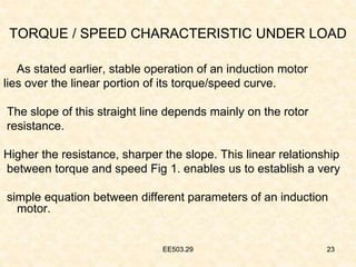
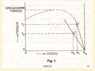
This document contains lecture notes on three-phase induction motors. It discusses topics like torque equations, torque-speed characteristics, synchronous speed, and formulas for calculating starting torque, maximum torque, and full-load torque. It also contains two sample problems demonstrating calculations of slip at maximum torque and full-load speed. The document aims to help students understand torque characteristics and solve problems related to induction motors.


![EE503.29 17
FORMULAE
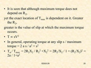
• Tst = k2 (R2
2+X2
2) = k2 R2/Z2
2 where k2 is some
other constant..
• Tst = k2R2/(R2
2+X2
2)
dTst/dR2 = [k2[1/ R2
2+X2
2 – R2(2R2/ (R2
2+X2
2 )2]
= 0
Or R2
2+X2
2 = 2R2
2 R2 = X2 , For
Maximum
Starting Torque.
17
EE503.29](https://image.slidesharecdn.com/ee503-230828173250-50560449/85/EE503-29-ppt-17-320.jpg)
![EE503.29 18
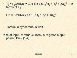
• T = k1 S E2
2R2/R2
2 + (sX2)2
k1 = 3/2ΠNs
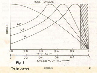
• T max = k1 (R2/X2).E2
2.R2 / R2
2+(R2/X2)2.X2
2 = k1
E2
2/2X2
k1 = 3/2ΠNs, T max =3/2ΠNs . E2
2/2X2 N-m
• T = Tb [ 2 / (sb/s)+(sb/s)]
18
EE503.29](https://image.slidesharecdn.com/ee503-230828173250-50560449/85/EE503-29-ppt-18-320.jpg)