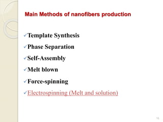
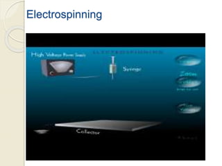
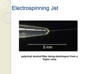
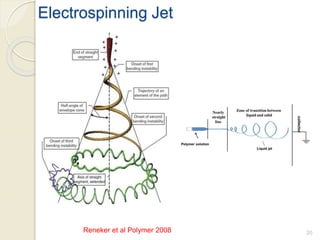
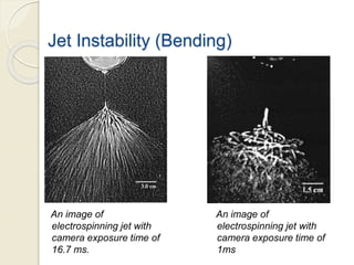
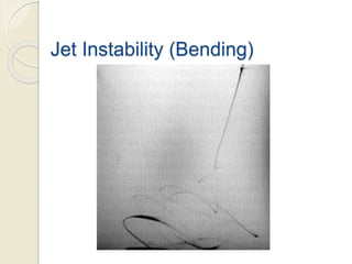
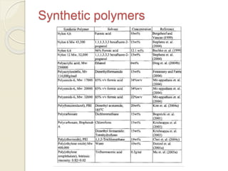
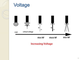
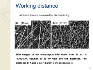
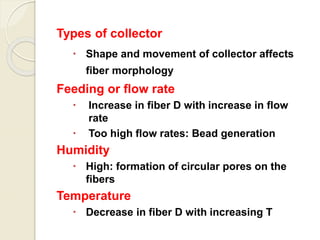
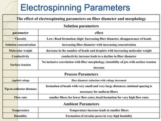
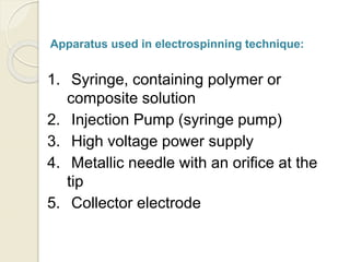
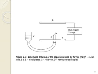
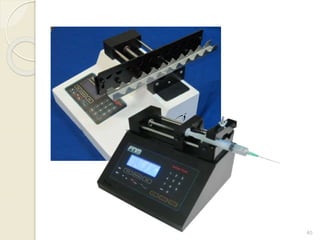
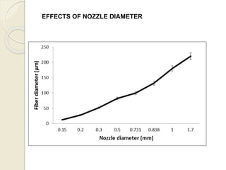
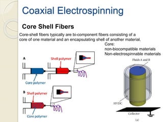
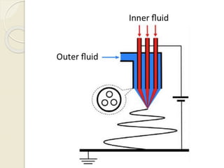
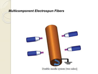
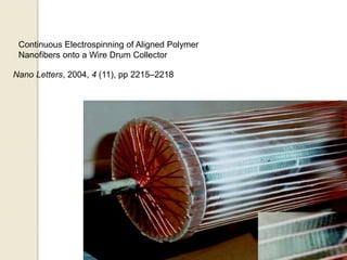
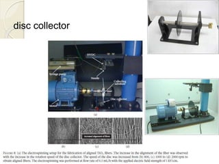
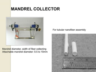
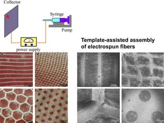
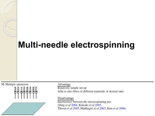
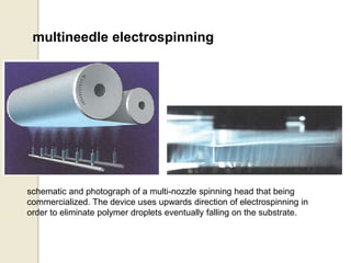
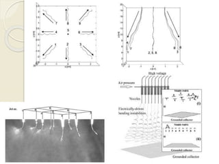
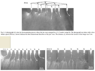
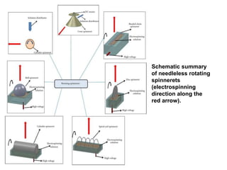
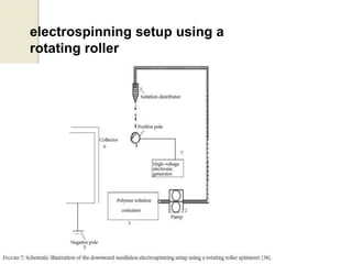
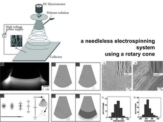
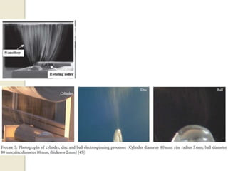
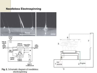
Electrospinning: A nanofiber
Fabrication Technique
Ali Abbasi
R&D Manager
ProgeneLink Sdn. Bhd.
ali.abbasi@progenelink.com
Nanotechnology
 NANO: is derived from Greek
Meaning “DWARF”
 In 1960, it was officially confirmed
as scale standard meaning 10−9 .
 1 nm means 1 billionth of a meter.
Definition
 NNI defines Nanotechnology as:
“science, engineering, and
technology conducted at the nanoscale,
which is about 1 to 100 nanometers”
Scale Comparison
Nanostructures
Dimension
s
Criteria Examples
0D all dimensions in the scale.
Nanoparticles,
quantum dots,
1D
1 dimension outside the
nanoscale.
Nanofibers,
Nanowires, nanorods,
nanotubes
2D
2 dimensions outside the
nanoscale.
Coatings, thin-film-
multilayers
3D
3 dimensions outside the
nanoscale.
Bulk nanoporous
materials
Nanoparticles
60 nm standard Gold Nanoperticles
Quantum Dots
semiconductors that are small enough to exhibit quantum mechanical
properties.
Nanowires
Nanotubes
Specific strength: 48000 kN.m/kg
more than 300 times higher than that of
high-carbon steel (154 kN.m/kg)
Nanocoating
fibers with diameter between 1 and 100 nm.
12
Nanofibers (250 nm)
Human Hair (75000 nm)
diameter of grass: 0.5 cm
diameter of trees: 30 cm
Nanofibers
Length
(mm)
Diameter
(roughly)
Volume
(mm3)
Surface area
(mm2)
A Human Hair 1000 75000 nm 1.4 235
A nanofiber 1000 250 nm 1.5×10⁻⁵ 0.78
1 hair can produce about 100000 nanofibers with 250 nm in diameters
100000 nanofibers have 78000 mm2 surface area (333 times higher).
A comparison
13
14
Nanofibers
Dependence of
Specific Surface
Area on fiber
diameter
Nanofibers
•Polymer nanofibers: including synthetic
polymer (PAs, PS,…) natural polymer (silk,
peptides, proteins, polysaccharides, …)
•Carbon nanofibers: produced by thermal
treatments of polymeric nanofibers
•Ceramic Nanofibers: produced by calcination
of polymeric nanofibers having ceramic
precursors
For all, we need polymeric nanofibers,
first.
15
Main Methods of nanofibers production
Template Synthesis
Phase Separation
Self-Assembly
Melt blown
Force-spinning
Electrospinning (Melt and solution)
16
Electrospinning
Electrospinning Jet
polyvinyl alcohol fiber being electrospun from a
Taylor cone
Electrospraying & Electrospinning
Reneker et al Polymer 2008
Electrospinning Jet
20
Jet Instability (Bending)
An image of
electrospinning jet with
camera exposure time of
16.7 ms.
An image of
electrospinning jet with
camera exposure time of
1ms
Jet Instability (Bending)
Synthetic polymers
Biopolymers
Electrospinning Parameters
There are 3 kinds of parameters
affecting electrospun nanofibers
properties:
1. Solution Parameters
2. Process parameters
3. Ambient Parameters
Different structural regimes during bead-fiber transition of polystyrene
electrospun from DMF. (a) beads only, (b) beads with incipient fibers, (c) bead-
on-string, and (d) bead-freefibers.
A thesis by Eda WORCESTER POLYTECHNIC INSTITUTE 2006
26
Solution Parameters
Concentration
SEM photographs of electrospun nanofibers from different
polymer concentration solutions.
Viscosity
27
Solution Parameters
SEM photographs of 5 wt. % chitosan nanofiber in acetic acid
solution mat with different molecular weight: (a) low molecular
weight (b) high molecular weight
molecular weight
28
Surface tension
In a fixed concentration, with reducing the surface
tension of the solution, beaded fibers can be
converted into smooth fibers.
Conductivity
when a small amount of salt or polyelectrolyte is added to the solution, the
increased charges carried by the solution will increase the stretching of
the solution.
As a result, smooth fibers are formed which may otherwise yield beaded
fibers. The increased in the stretching of the solution also will tend to yield
fibers of smaller diameter.
30
the affection of the applied voltages on the diameter of electrospun
fibers is a little controversial.
Effect of voltage on
morphology and fiber
diameter distribution
from a 7.4 wt. %
PVA/water solution (DH =
98 %, tip–target distance
= 15 cm, flow rate = 0.2
ml/h). Voltages a) 5; b )
8; c )10; and d ) 13 kV.
31
Voltage
32
Voltage
SEM images of the electrospun PSF fibers from 20 wt. %
PSF/DMAC solution at 10 kV with different distances. The
distances of A and B are 10 and 15 cm, respectively.
33
Working distance
Minimum distance is required for electrospinning
Types of collector
 Shape and movement of collector affects
fiber morphology
Feeding or flow rate
 Increase in fiber D with increase in flow
rate
 Too high flow rates: Bead generation
Humidity
 High: formation of circular pores on the
fibers
Temperature
 Decrease in fiber D with increasing T
Electrospinning Parameters
The effect of electrospinning parameters on fiber diameter and morphology
Solution parameters
parameter effect
Viscosity Low: Bead formation; high: Increasing fiber diameter, disappearance of beads
Solution concentration increasing fiber diameter with increasing concentration
Molecular weight decrease in the number of beads and droplets with increasing molecular weight
Conductivity conductivity increase leads to a decline in fiber diameter
Surface tension
No inclusive correlation with fiber morphology; instability of jets with surface tension
increase
Process Parameters
Applied voltage fiber diameter reduction with voltage increment
Tip-to-collector distance
formation of beads with very small and very large distances; minimal spacing is
necessary for uniform fibers
Flow rate smaller fibers for lower flow rates; bead formation for very high flow rates
Ambient Parameters
Temperature Temperature increase leads to smaller fibers
Humidity Formation of circular pores in very high humidity
Apparatus used in electrospinning technique:
1. Syringe, containing polymer or
composite solution
2. Injection Pump (syringe pump)
3. High voltage power supply
4. Metallic needle with an orifice at the
tip
5. Collector electrode
Injection Systems &
Needles
38
39
40
EFFECTS OF NOZZLE DIAMETER
Core Shell Fibers
Core:
non-biocompatible materials
Non-electrospinnable materials
Core-shell fibers typically are bi-component fibers consisting of a
core of one material and an encapsulating shell of another material.
Coaxial Electrospinning
Multicomponent Electrospun Fibers
Collectors
45
PLATE COLLECTOR
Useful for optimization of spinning
conditions and creation of a small
amount of sample
There are two circles of nanofiber mats.
Form center to outside of the circle the
content of nanofibers is reduced so non-
homogen mats will be formed in this type
of collector.
Edge type collector
Grid type collector
Roll to Roll COLLECTOR
It is a collector who can make the
Nano fiber sheet of 10 m×20 cm
with the LAB machine.
Parallel collector
The positioning of the collector
affects fiber deposition.
53
Fabrication of Aligned Fibrous
Arrays by Magnetic
Electrospinning
Continuous Electrospinning of Aligned Polymer
Nanofibers onto a Wire Drum Collector
Nano Letters, 2004, 4 (11), pp 2215–2218
disc collector
MANDREL COLLECTOR
For tubular nanofiber assembly
Mandrel diameter, width of fiber collecting
Attachable mandrel diameter: 0.5 to 10mm
57
Template-assisted assembly
of electrospun fibers
58
Scale-up electrospinning
59
Multi-needle electrospinning
multineedle electrospinning
schematic and photograph of a multi-nozzle spinning head that being
commercialized. The device uses upwards direction of electrospinning in
order to eliminate polymer droplets eventually falling on the substrate.
Needleless
Electrospinning
Recently, needleless electrospinning appeared as an
alternative electrospinning technology with the aim of producing
nanofibers on a large scale from a compact space.
Schematic summary
of needleless rotating
spinnerets
(electrospinning
direction along the
red arrow).
electrospinning setup using a
rotating roller
a needleless electrospinning
system
using a rotary cone
Needleless Electrospinning
coil spinneret
Wire spinneret
Wire spinneret

Electrospinning