The document discusses the development and effects of a grid-adaptive four-tap low-pass interpolation filter on hole-filled depth images, aimed at minimizing noise and reducing processing time. It compares various finite impulse response filters, demonstrating that the proposed four-tap filter provides high peak signal-to-noise ratios (PSNR) while significantly decreasing time complexity compared to conventional methods. The findings suggest integrating hole-filling and interpolation into one process, improving efficiency in depth image enhancement applications.
![Natarajan Meghanathan et al. (Eds) : WiMONe, NCS, SPM, CSEIT - 2014
pp. 185–189, 2014. © CS & IT-CSCP 2014 DOI : 10.5121/csit.2014.41214
EFFECT OF GRID-ADAPTIVE
INTERPOLATION OVER DEPTH IMAGES
Arbaaz Singh
Department of Computer science & Engineering,
Indian Institute of Technology, Ropar, Punjab, India
arbaazs@iitrpr.ac.in
ABSTRACT
A suitable interpolation method is essential to keep the noise level minimum along with the time-
delay. In recent years, many different interpolation filters have been developed for instance
H.264-6 tap filter, and AVS- 4 tap filter. This work demonstrates the effects of a four-tap low-
pass tap filter (Grid-adaptive filter) on a hole-filled depth image. This paper provides (i) a
general form of uniform interpolations for both integer and sub-pixel locations in terms of the
sampling interval and filter length, and (ii) compares the effect of different finite impulse
response filters on a depth-image. Furthermore, the author proposed and investigated an
integrated Grid-adaptive filter, that implement hole-filling and interpolation concurrently,
causes reduction in time-delay noticeably along with high PSNR .
KEYWORDS
Depth Images, Hole filling, Interpolation, Interpolation filter
1. INTRODUCTION
In 3-D computer graphics, a depth map is an image or image channel that contains information
relating to the distance of the surfaces of scene objects from a viewpoint [1]. Once the original
image and depth image is given, 3-D can be synthesized by mapping pixel coordinates one by one
according to its depth value. It is the next emerging revolution after the high definition video and
is the key technology in advanced three dimensional television systems (3-D TV) and free-view
television systems [2-4]. A new member of 3-D sensor family, kinect has drawn great attention of
researchers in the field of 3-D computer vision for its advantage of consumer price and real time
nature. Based on a structured light technique, Kinect is able to generate depth and colour images
at a speed of about 30 fps [5]. However, limited by depth measuring principle and object surface
properties, the depth image captured by the Kinect contains missing data as well as noise. These
areas of missing data are known as holes. Holes appear due to sharp horizontal changes in depth
image, thus the location and size of holes differ from frame to frame. Several attempts are made
to remove the noise and filling of holes with the correct data to make it suitable for different
applications by means of bilateral and median-filters [6]. Apart from hole-filling, image
interpolation as well occurs in all digital pictures at several stages [7]. Interpolation is the process
of determining the values of a function at positions lying between its samples. It achieves this
process by fitting a continuous function through the discrete input samples. This permits input
values to be evaluated at arbitrary positions excluding those defined at the sample points.
Interpolation is required to produce a larger image than the one captured and finds an imperative](https://image.slidesharecdn.com/effectofgrid-adaptiveinterpolationoverdepthimages-150104230107-conversion-gate01/75/Effect-of-grid-adaptive-interpolation-over-depth-images-1-2048.jpg)
![186 Computer Science & Information Technology (CS & IT)
consign in transmission of 3-D images. 3-D images have been used in robotic guidance, product
profiling and object tracking, in battle preparation, medical diagnosis and many more [8]. These
all applications require both hole-filling and interpolation to provide a preferred output. A suitable
interpolation method is essential to keep the noise level minimum along with the time-delay. The
standard/conventional procedure to interpolate a depth image is to first fill the holes and then
apply the interpolation filter that leads to low PSNR and a great time-complexity. In recent years,
many different interpolation filters have been developed for instance H.264-6 Tap filter, AVS- 4
tap filter and so on [9-10].
The standard/conventional procedure to interpolate a depth image is to first fill the holes and then
apply the interpolation filter that leads to low PSNR and a great time-complexity. Recently, a
texture-adaptive hole-filling algorithm is proposed for post-processing of rendered image on 3D
video to save the computational cost [11]. The algorithm first determines the type of holes, and
then fills the missed pixels in raster-order depending upon hole types and texture gradient of
neighbors with simple data operation, which benefits for fast processing. Further, the quality of
virtual view images from rendering is demonstrated by establishing a connection of pixel
coordinate warping between reference image and virtual image in the rendering process, to make
a quick decision on the position of hole region and its edge [12]. Subsequently, by outward
expanding the edge of holes, warping error pixels are covered. Then, hole-filling is through using
use mean filter and the image restoration method after eliminating the false contour by image
synthesis. Nonlinear filters called Spline Adaptive Filters (SAFs), implementing the linear part of
the Wiener architecture with an IIR filter instead of an FIR one are also come into picture to
improve the PSNR and computational delay [13]. This paper investigates a four-tap Grid-adaptive
filter on a hole-filled depth image that provides uniform interpolations for both integer and sub-
pixel locations in terms of the sampling interval and filter length. Further, it compares with other
different finite impulse response filters and investigates the integrated grid adaptive filter to
reduce the time delay.
2. THEORETICAL & EXPERIMENTAL ANALYSIS
The depth image I is a 2D grid of KV x KH pixels. The pixels denote the distance of the objects in
real scene according to its image co-ordinates [4]. The holes are areas in the image that have
invalid (missing) data. Each pixel has 8 neighbouring pixels that share a face or a vertex with the
centre pixel. Our goal is to go through the image and fill up the holes in the image. Let each pixel
in the image be denoted as I (v, h), where v, h can be any integer value between 0 and KV, KH
respectively. If I (v, h) = 0, then that pixel is a part of a hole. A 3 x 3 gaussian weighted averaging
filter is used to fill the holes. The filter takes the weighted average of the depth values of its
neighbours and replaces the hole with the obtained averaged value. The weights are decided such
that the neighbour pixels, that are holes themselves, are ignored while the non-zero valued pixels
are used to find the new value of the hole-pixel.
Let the vertical and horizontal distances between the two nearest known pixels be Tv andTh ,
respectively. Subsequently, the aim is to insert and interpolate Nv and Nh pixels within the
intervals of Tv and Th respectively. So, after the interpolation, we will have a sum of
[ (1 ) ] [ (1 ) ]K N N K N Nv v v h h h+ − × + − pixels and the sampling intervals for vertical and horizontal
directions will be changed to /(1 )D T Nv v v= + and /(1 )D T Nh h h= + respectively. For example,
Figure 1 shows the case of 1N Nv h= = with / 2D Tv v= and / 2D Th h= .](https://image.slidesharecdn.com/effectofgrid-adaptiveinterpolationoverdepthimages-150104230107-conversion-gate01/75/Effect-of-grid-adaptive-interpolation-over-depth-images-2-2048.jpg)
![Computer Science & Information Technology (CS & IT) 187
Figure 1. Uniformly spaced interpolation (a) before interpolation with known (bold square) pixels, (b) After
Interpolation for missing (dotted square) pixels
Therefore, the general formula for 1-D interpolation filter will be
( ) ( ) ( )
1
M
y KT n y KT mT P mT n
m M
+ ∆ = + − ∆∑
= +
… (1)
Where, n denotes the pixel location to be interpolated within two reference samples i.e. (KT) and
(KT + T). So, we need to evaluate equation (1) for all (1-N). The expression (1) covers both
fractional and integral pixel interpolations. For the fractional locations, the value of ∆ is kept less
than 1 while for integral locations the value of ∆ is always greater than 1. The proposed-4 tap
filter is obtained using the Langrage interpolation, which is used to generalise the linear
interpolation by approximating the sinc function [10]. The Lagrange interpolation kernel is an Lth
order polynomial function determined by L+1 values in the following function,
… (2)
Where,
∏ ∆−−
∆−−=∆−
k
nmT nmtt
nktttQ
))((
))(()( … (3)
For any sampling grid layout and scale, the filter coefficients can be calculated by fitting (3) to
the grid. The PSNR is measured for different filters such as the linear averaging filter, H.264-6
Tap filter with coefficients (1,-5, 20, 20, -5, 1 ) / 32, the AVS- 4 Tap filter with coefficients ( -1,
5, 5,-1 ) / 8 and the proposed-4 tap grid adaptive filter with coefficients ( -1, 9, 9, -1 ) / 16 to
recommend the best one. All test images are taken from the Middlebury Database (2006) and are
expanded as the same sampling layout and scale of the proposed 4-Tap filter i.e. doubling the
number of rows and columns with T = 2, N = 1, M= 2, and ∆ = 1). For evaluating the
performance the simulated filters, all images are expanded at the same sampling layout and scale
of the filters (i.e. doubling the number of rows and columns with 2T = , 1N = , 2M = , and
1D = ). For computation, the images are reduced to half before interpolation so that the size of
image remains same after hole-filling and interpolation. The PSNR is calculated between a
perfect image and its noisy approximation and can be easily defined via mean squared error
)(
)(
)(
∆−
=∆−+
∆−
∆−
nmTQ
tQ
nmTtP
nmT
nmT](https://image.slidesharecdn.com/effectofgrid-adaptiveinterpolationoverdepthimages-150104230107-conversion-gate01/75/Effect-of-grid-adaptive-interpolation-over-depth-images-3-2048.jpg)
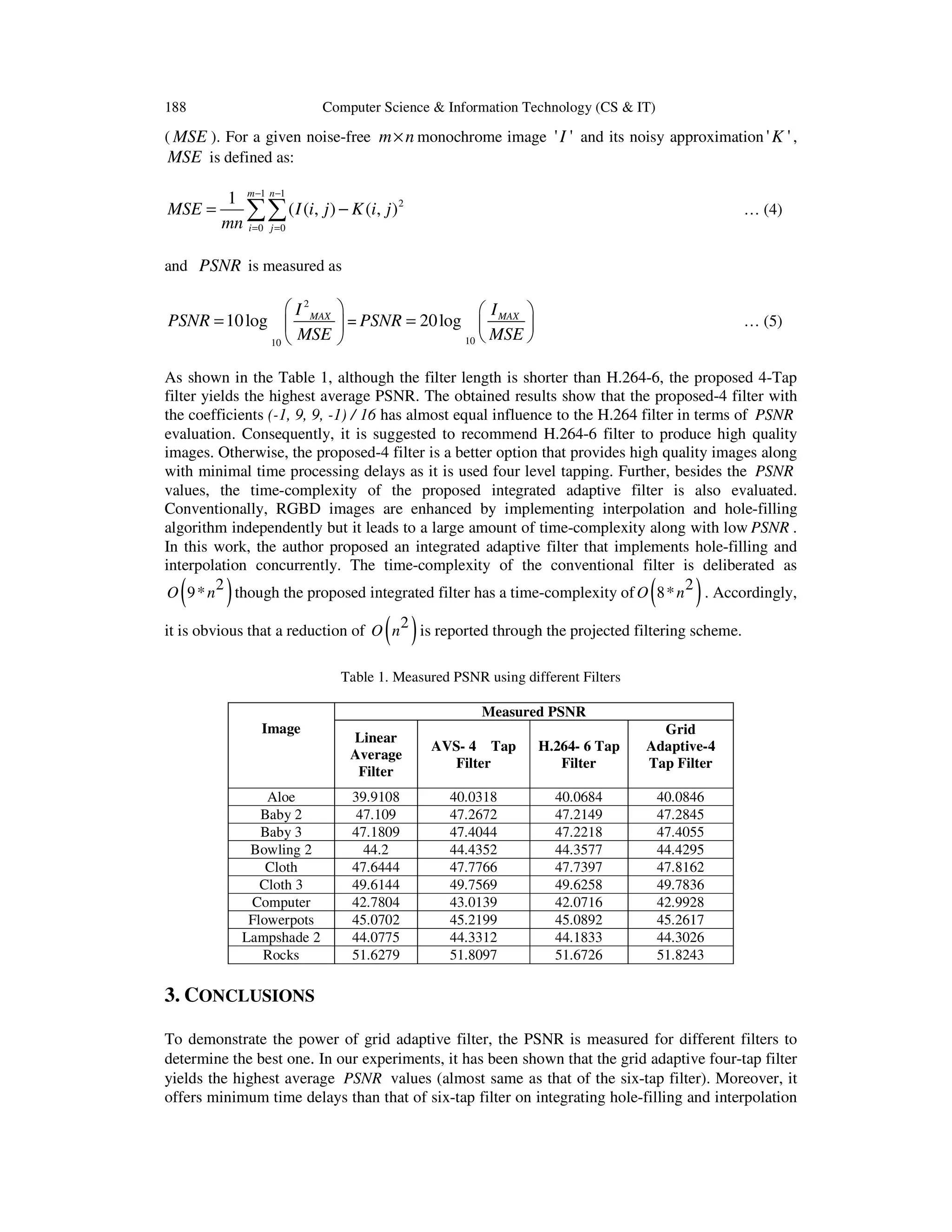
![Computer Science & Information Technology (CS & IT) 189
in tandem. Accordingly, it is suggested to use the proposed integrated Grid adaptive filter for the
enhancement of depth images.
ACKNOWLEDGEMENT
I thank to Professor Chee Sun Won, Department of Electronics and Electrical Engineering,
Dongguk University, Seoul, South Korea for his kind and valuable guidance for carrying out this
work. I also thank to the Department of Electronics and Electrical Engineering, Dongguk
University, Seoul, South Korea for providing lab facility and technical support.
REFERENCES
[1] Depth Map, Wikipedia accessed on 17th July, 2014, http://en.wikipedia.org/wiki/Depth_map
[2] Kubota, A. Smolic, M. Magnor, M. Tanimoto, T. Chen, and C. Zhang, (2007) “Multi-view Imaging
and 3DTV”, IEEE Signal Processing Magazine, Vol. 24, No. 6, pp 10-21.
[3] T. Fujii, and M. Tanimoto, (2002) “Free viewpoint TV system based on ray-space representation”, in
proceeding of Three Dimensional TV, Video and Display, 175, SPIE 4864, 1st November, 2002,
doi:10.1117/12.454905
[4] S. L. Forman, and L. A. Steen, “Case study: Image Processing”,
http://www.stolaf.edu/people/steen/Projects/ ATE/imp.html.
[5] Li Chen, Hui Lin, and Shutao Li, (2012) “Depth image enhancement for Kinect using region growing
and bilateral filter”, 21st International Conference on Pattern Recognition (ICPR 2012), Tsukuba,
Japan, pp 3070 - 3073.
[6] S. Matyunin, D. Vatolin, Y. Berdnikov, and M. Smirnov, (2011) “Temporal filtering for depth maps
generated by Kinect depth camera”, 3DTV Conference: The True Vision-Capture, Transmission and
Display of 3D Video (3DTV-CON), pp 1-4, Doi: 10.1109/3DTV.2011.5877202
[7] Digital Image Interpolation, http://www.cambridgeincolour.com/tutorials/ image-interpolation.htm
[8] Andrew Wilson, “3D imaging systems target multiple applications”, http://www.vision-
systems.com/articles/print/volume-18/issue-9/features/3d-imaging-systems-target-multiple-
applications.html
[9] Lehmann, T.M., Gonner, C., and Spitzer, K., (1999) ‘Survey: interpolation methods in medical image
processing’, IEEE Trans. Med. Imag., Vol. 18, No. 11, 1999, pp 1049–1075.
[10] Chee Sun Won, (2013) “Grid Adaptive Interpolation Filter”, Electronic Letters, Vol. 49, No. 3, pp
181-182, Doi: 10.1049/el.2012.2481
[11] Linwei Zhu, Mei Yu, Gangyi Jiang, Xiangying Mao, Songyin Fu, Ting Luo, “A New Virtual View
Rendering Method based on Depth Map for 3DTV3DTV; virtual view rendering; depth; false
contour; holes filling; image restoration”, Procedia Engineering, Volume15, pp.1115-1119, 2011
[12] Michele Scarpiniti, Danilo Comminiello, Raffaele Parisi, Aurelio Uncini,“ Nonlinear system
identification using IIR Spline Adaptive Filters”, Signal Processing, Volume 108, pp.30-35, March
2015
[13] Chee Sun Won, “Grid Adaptive Interpolation Filter”, Electronic Letters, Volume 49, Issue 3, pp. 181-
182, 31st January 2013, doi: 10.1049/el.2012.2481
AUTHOR
I, Arbaaz Singh am currently studying in the field of Image Processing in the department
of Computer Science & Engineering at Indian Institute of Technology, Ropar, Punjab,
India. I worked as a research Intern at Dongguk University under the kind guidance of
Professor Chee Sun Won in the field of Depth Images. My areas of interest are Depth
image processing and designing issues of Interpolation filters.](https://image.slidesharecdn.com/effectofgrid-adaptiveinterpolationoverdepthimages-150104230107-conversion-gate01/75/Effect-of-grid-adaptive-interpolation-over-depth-images-5-2048.jpg)