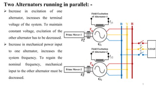
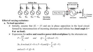
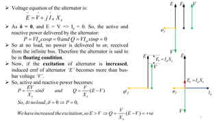
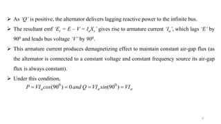
Electrical Machines-II
6th Semester, EE and EEE
By
Dr. Binod Kumar Sahu
Associate Professor, Electrical Engg.
Siksha ‘O’ Anusandhan, Deemed to be University,
Bhubaneswar, Odisha, India
Lecture-20
2
Learning Outcomes: - (Previous Lecture_19)
 Numerical on Effect of varying field excitation on two alternators running in
parallel:
3
Learning Outcomes: - (Today’s Lecture_20)
 Synchronous generator (Alternator) on an infinite bus.
 Effect of change in varying excitation on an alternator connected to infinite
bus at no load.
4
Alternator on an Infinite Bus: -
Infinite Bus: -
 A bus-bar that maintains constant voltage and constant frequency irrespective of the
load variation on it is called an infinite bus.
 A large number of alternators interconnected together to form a supply system
may be regarded as an infinite bus.
 So, an infinite bus is a voltage source having zero internal impedance and infinite
rotational inertia.
 Therefore, a synchronous machine switched on to or disconnected from the infinite
bus, can not change the voltage and frequency of the supply system.
5
YB R
LOAD
G2
Prime Mover-2
G1
Prime Mover-1
Te
Tm
Tm
Te
1fI
2fI
Field Excitation
of Alternator-1
Field Excitation
of Alternator-2
Two Alternators running in parallel: -
 Increase in excitation of one
alternator, increases the terminal
voltage of the system. To maintain
constant voltage, excitation of the
other alternator has to be decreased.
 Increase in mechanical power input
to one alternator, increases the
system frequency. To regain the
nominal frequency, mechanical
input to the other alternator must be
decreased.
6
Effect of varying excitation:-
a. No load operation: -
 Initially, assume that |E| = |V| and are in phase opposition in the local circuit
formed by interconnection of incoming alternator and infinite bus (load angle δ =
0 at no load).
 Expression for active and reactive power delivered/phase by the alternator are
G1 G2 G3 Gn
…. Incoming
Alternator
Infinite Bus
XSXS XS XSXS
Infinite BusAlternator
XS
V = Constant
f = Constant
Ia
E
Field Excitation
of Alternator
Prime Mover-1
Te
Tm
( )
, , 0 0, ( )
, 0.
s s
s
EV V
P sin and Q Ecos V
X X
V
So At noload P and Q E V
X
and as E V Q
 

  
    
 
7
 Voltage equation of the alternator is:
 As δ = 0, and E = V => Ia = 0. So, the active and
reactive power delivered by the alternator:
 So at no load, no power is delivered to or, received
from the infinite bus. Therefore the alternator is said to
be in floating condition.
 Now, if the excitation of alternator is increased,
induced emf of alternator ‘E’ becomes more than bus-
bar voltage ‘V’.
 So, active and reactive power becomes:
0 0a aP VI cos and Q VI sin    
a sE V j I X
  
 
( )
, , 0 0,
, ( )
s s
s
EV V
P sin and Q E V
X X
So At noload P
V
Wehaveincreased theexcitation so E V Q E V ve
X


  
  
     
V
E E V
f
r a sE I X
aI
E
V
E
V
r a sE I X
'f f
8
 As ‘Q’ is positive, the alternator delivers lagging reactive power to the infinite bus.
 The resultant emf ‘Er = E – V = IaXs’ gives rise to armature current ‘Ia’, which lags ‘E’ by
900 and leads bus voltage ‘V’ by 900.
 This armature current produces demagnetizing effect to maintain constant air-gap flux (as
the alternator is connected to a constant voltage and constant frequency source its air-gap
flux is always constant).
 Under this condition,
0 0
(90 ) 0 (90 )a a aP VI cos and Q VI sin VI   
9
 Now, if the excitation of alternator is decreased,
induced emf of alternator ‘E’ becomes less than bus-
bar voltage ‘V’.
 So the active and reactive power becomes:
 Decrease in excitation of alternator, reduces its
induced emf causing armature current ‘Ia’.
( )
, , 0 0,
, ( )
s s
s
EV V
P sin and Q E V
X X
So At noload P
V
Wehavedecreased theexcitation E V Q E V ve
X


  
  
     
aI
E
V
r a sE I X
'f
V
E
f
10
 As ‘Q’ is negative, the alternator receives lagging reactive power or delivers
leading reactive power to the infinite bus.
 Now, in this case armature current ‘Ia’ leads induced emf (E) by 900 which
increases the air-gap flux, due to magnetizing effect of armature reaction. This
magnetizing effect again maintains a constant air-gap flux.
 Under this condition,
 So any change in field excitation, automatically sets in an armature current
‘Ia’ which helps in regaining the synchronism.
0 0
( 90 ) 0 ( 90 )a a aP VI cos and Q VI sin VI      
11
Thank you

Eet3082 binod kumar sahu lecturer_20

  • 1.
    Electrical Machines-II 6th Semester,EE and EEE By Dr. Binod Kumar Sahu Associate Professor, Electrical Engg. Siksha ‘O’ Anusandhan, Deemed to be University, Bhubaneswar, Odisha, India Lecture-20
  • 2.
    2 Learning Outcomes: -(Previous Lecture_19)  Numerical on Effect of varying field excitation on two alternators running in parallel:
  • 3.
    3 Learning Outcomes: -(Today’s Lecture_20)  Synchronous generator (Alternator) on an infinite bus.  Effect of change in varying excitation on an alternator connected to infinite bus at no load.
  • 4.
    4 Alternator on anInfinite Bus: - Infinite Bus: -  A bus-bar that maintains constant voltage and constant frequency irrespective of the load variation on it is called an infinite bus.  A large number of alternators interconnected together to form a supply system may be regarded as an infinite bus.  So, an infinite bus is a voltage source having zero internal impedance and infinite rotational inertia.  Therefore, a synchronous machine switched on to or disconnected from the infinite bus, can not change the voltage and frequency of the supply system.
  • 5.
    5 YB R LOAD G2 Prime Mover-2 G1 PrimeMover-1 Te Tm Tm Te 1fI 2fI Field Excitation of Alternator-1 Field Excitation of Alternator-2 Two Alternators running in parallel: -  Increase in excitation of one alternator, increases the terminal voltage of the system. To maintain constant voltage, excitation of the other alternator has to be decreased.  Increase in mechanical power input to one alternator, increases the system frequency. To regain the nominal frequency, mechanical input to the other alternator must be decreased.
  • 6.
    6 Effect of varyingexcitation:- a. No load operation: -  Initially, assume that |E| = |V| and are in phase opposition in the local circuit formed by interconnection of incoming alternator and infinite bus (load angle δ = 0 at no load).  Expression for active and reactive power delivered/phase by the alternator are G1 G2 G3 Gn …. Incoming Alternator Infinite Bus XSXS XS XSXS Infinite BusAlternator XS V = Constant f = Constant Ia E Field Excitation of Alternator Prime Mover-1 Te Tm ( ) , , 0 0, ( ) , 0. s s s EV V P sin and Q Ecos V X X V So At noload P and Q E V X and as E V Q             
  • 7.
    7  Voltage equationof the alternator is:  As δ = 0, and E = V => Ia = 0. So, the active and reactive power delivered by the alternator:  So at no load, no power is delivered to or, received from the infinite bus. Therefore the alternator is said to be in floating condition.  Now, if the excitation of alternator is increased, induced emf of alternator ‘E’ becomes more than bus- bar voltage ‘V’.  So, active and reactive power becomes: 0 0a aP VI cos and Q VI sin     a sE V j I X      ( ) , , 0 0, , ( ) s s s EV V P sin and Q E V X X So At noload P V Wehaveincreased theexcitation so E V Q E V ve X               V E E V f r a sE I X aI E V E V r a sE I X 'f f
  • 8.
    8  As ‘Q’is positive, the alternator delivers lagging reactive power to the infinite bus.  The resultant emf ‘Er = E – V = IaXs’ gives rise to armature current ‘Ia’, which lags ‘E’ by 900 and leads bus voltage ‘V’ by 900.  This armature current produces demagnetizing effect to maintain constant air-gap flux (as the alternator is connected to a constant voltage and constant frequency source its air-gap flux is always constant).  Under this condition, 0 0 (90 ) 0 (90 )a a aP VI cos and Q VI sin VI   
  • 9.
    9  Now, ifthe excitation of alternator is decreased, induced emf of alternator ‘E’ becomes less than bus- bar voltage ‘V’.  So the active and reactive power becomes:  Decrease in excitation of alternator, reduces its induced emf causing armature current ‘Ia’. ( ) , , 0 0, , ( ) s s s EV V P sin and Q E V X X So At noload P V Wehavedecreased theexcitation E V Q E V ve X               aI E V r a sE I X 'f V E f
  • 10.
    10  As ‘Q’is negative, the alternator receives lagging reactive power or delivers leading reactive power to the infinite bus.  Now, in this case armature current ‘Ia’ leads induced emf (E) by 900 which increases the air-gap flux, due to magnetizing effect of armature reaction. This magnetizing effect again maintains a constant air-gap flux.  Under this condition,  So any change in field excitation, automatically sets in an armature current ‘Ia’ which helps in regaining the synchronism. 0 0 ( 90 ) 0 ( 90 )a a aP VI cos and Q VI sin VI      
  • 11.