Contents:
• Basic TransmissionTheory
• System Noise Temperature &G/T Ratio
• Design of downlinks
• Uplink design
• Design of satellite links for specified C/N
3.
Basic Transmission Theory:
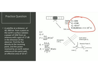
•The calculation of power received by an earth station
from a satellite is fundamental to the understanding of
satellite communication.
• Consider a transmitting source, in free space, radiating
a total power Pt watts uniformly in all directions.
• Such source is called isotropic.
• At a distance R meters from isotropic source, flux
density crossing the surface
F= Pt / 4 πR2 (W/m2 )
5.
◻For a transmitterwith output Pt watts driving a
lossless antenna with gain Gt , the flux density at
distance R meters is
F= Pt Gt / 4 πR2 (W/m2 )
◻The product Pt Gt is called effective isotropic radiated
power or EIRP,it describes the combination of
transmitting power &antenna gain in terms of an
equivalent isotropic source with power Pt Gt watts.
6.
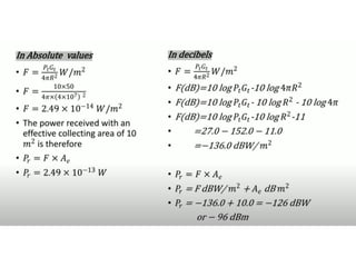
If we hadan ideal receiving antenna with an aperture
of Am2 , we would collect power Pr watts given by
Pr = F *A watts
A practical antenna with physical aperture area of A m2
will not deliver power as given in above equation.
Some of the energy incident on aperture is reflected away
from the antenna, some is absorbed by lossy components.
The effective aperture Ae is
Ae = ηAA
Where ηA aperture efficiency of the antenna.
For parabolic reflector
For Horn antennas
ηA= 50 to 75%
ηA = 90%
7.
◻Thus the powerreceived by real antenna with effective
aperture area Ae m2 is
Pr = Pt Gt Ae / 4 πR2 (watts)……..(A)
◻Afundamental relation in antenna theory is gain &
area of an antenna are related by
G = 4π Ae / λ2
◻Substituting above equation in equation (A) gives
Pr = [Pt Gt Gr/ (4 πR / λ )2 ]watts
◻This expression is known as link equation &essential
in calculation of power received in any radio link.
◻The term (4 πR / λ )2 is known as path loss Lp .
8.
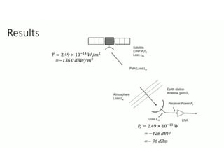
◻Collecting various factors,we can write
Power received
= (EIRP * Receiving antenna gain / path loss)watts
◻In decibel, wehave
Pr = EIRP + Gr – Lp …
…
…
…
…
…
……..(B)
Where EIRP= 10log10 (Pt Gt ) dBW
Gr = 10log10(4π Ae / λ2 )dB
Lp = 10log10(4 πR / λ )2 dB
9.
◻Equation B representsan idealized case, in which there
are no additional losses in the link.
◻In practice, we need to take account of a more complex
situation in which we have losses in atmosphere due to
attenuation by oxygen, water vapor and rain, losses in
the antennas at each end of the link.
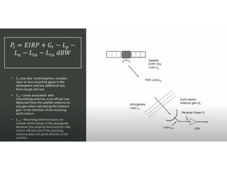
◻So equation Bcan be written as
Pr = EIRP + Gr – Lp – La - Lta – Lra dBW
where La = attenuation in atmosphere
Lta = losses associated with transmitting antenna
Lra = losses associated with receivingantenna
11.
◻The received power,Pr is commonly referred to as
carrier power, C.
◻This is because most satellite links use either
frequency modulation for analog transmission or
phase modulation for digital systems.
◻In both of the modulation schemes, the amplitude of
the carrier is not changed when data are modulated
onto the carrier, so carrier power C is always equal to
received power Pr.
15.
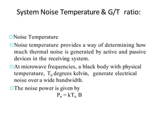
System Noise Temperature& G/T ratio:
◻Noise Temperature
◻Noise temperature provides a way of determining how
much thermal noise is generated by active and passive
devices in the receiving system.
◻At microwave frequencies, a black body with physical
temperature, Tp degrees kelvin, generate electrical
noise over a wide bandwidth.
◻The noise power is given by
Pn = kTn B
16.
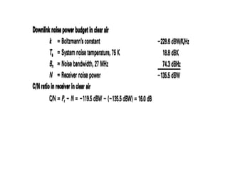
Where
k= Boltzmann’s constant=1.38*10-23 J/K
=-228.6 dBW/K/Hz
Tn = Noise temperature of source in K
B= noise bandwidth in which noise power is
measured, in Hz.
17.
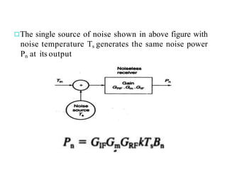
System noise temperatureTs , is the noisetemperature
of noise source at the input of noiseless receiver, which
gives same noise power as the original receiver,
measured at the output of receiver.
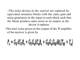
The noisy devicesin the receiver are replaced by
equivalent noiseless blocks with the same gain and
noise generators at the input to each block such that
the block produce same noise at its output as the
device it replaces.
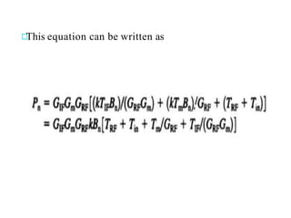
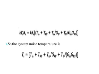
The total noise power at the output of the IF amplifier
of the receiver is given by
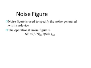
Noise Figure
◻Noise figureis used to specify the noise generated
within adevice.
◻The operational noise figure is
NF = (S/N)in /(S/N)out
25.
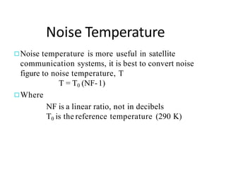
Noise Temperature
◻Noise temperatureis more useful in satellite
communication systems, it is best to convert noise
figure to noise temperature, T
T = T0 (NF-1)
◻Where
NF is a linear ratio, not in decibels
T0 is the reference temperature (290 K)
26.
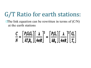
G/T Ratio forearth stations:
The link equation can be rewritten in terms of (C/N)
at the earth stations
27.
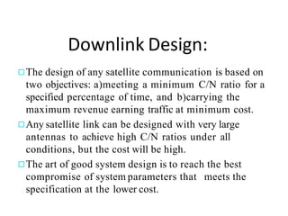
Downlink Design:
◻The designof any satellite communication is based on
two objectives: a)meeting a minimum C/N ratio for a
specified percentage of time, and b)carrying the
maximum revenue earning traffic at minimum cost.
◻Any satellite link can be designed with very large
antennas to achieve high C/N ratios under all
conditions, but the cost will be high.
◻The art of good system design is to reach the best
compromise of system parameters that meets the
specification at the lower cost.
28.
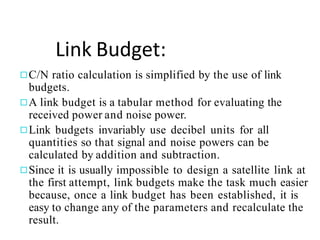
Link Budget:
◻C/N ratiocalculation is simplified by the use of link
budgets.
◻A link budget is a tabular method for evaluating the
received power and noise power.
◻Link budgets invariably use decibel units for all
quantities so that signal and noise powers can be
calculated by addition and subtraction.
◻Since it is usually impossible to design a satellite link at
the first attempt, link budgets make the task much easier
because, once a link budget has been established, it is
easy to change any of the parameters and recalculate the
result.
31.
Uplink Design:
◻The Uplinkdesign is easier than the downlink, since
an accurately specified carrier power must be
presented at the satellite transponder and it is often
feasible to use much higher power transmitters at
earth stations than can be used on a satellite.
◻The cost of transmitters tend to be high compared
with the cost of receiving equipment in satellite
communication system.
32.
◻Earth station transmitterpower is set by the power
level required at the input to the transponder.
◻Analysis of the uplink requires calculation of the
power level at the input to the transponder so that the
uplink C/N ratio can be found.
◻The link equation is used to make this calculation.
◻Let (C/N)up be the specified C/N ratio in the
transponder, measured in an noise bandwidth BnHz.
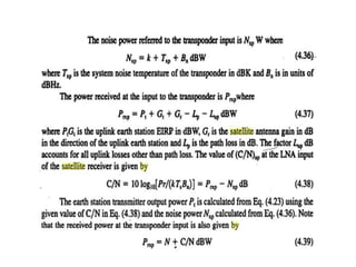
34.
◻At frequencies above10GHz, propagating
disturbances in the form of fading in rain causes the
received power level at the satellite to fall.
◻This lowers the uplink C/N ratio in the transponder ,
which lowers the overall (C/N)o ratio in the earth
station receiver.
35.
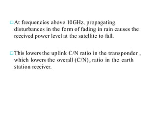
Design for SpecifiedC/N:
◻ The S/N ratio in the baseband channel of an earth station receiver is
determined by the ratio of the carrier power to the noise power in the IF
amplifier at the input to the demodulator. The noise present in the IF
amplifier comes from many sources. In this analysis of uplink and downlink
we have considered only the receiver thermal noise and noise radiated by
atmospheric gases and rain in the slant path.
◻ When more than one C/N ratio is present in the link, we can add the
individual C/N ratios reciprocally to obtain overall C/N ratio denoted
as (C/N)o
◻ The overall (C/N)o ratio is
(C/N)o = 1/[1/(C/N)1 + 1/(C/N)2 +_ _ _ __]
36.
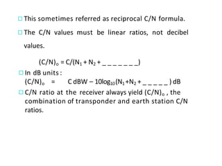
◻This sometimes referredas reciprocal C/N formula.
◻The C/N values must be linear ratios, not decibel
values.
(C/N)o = C/(N1 + N2 + _ _ _ _ _ _ _)
◻In dB units :
(C/N)o = C dBW – 10log10(N1+N2 + _ _ _ _ _ ) dB
◻C/N ratio at the receiver always yield (C/N)o , the
combination of transponder and earth station C/N
ratios.
37.
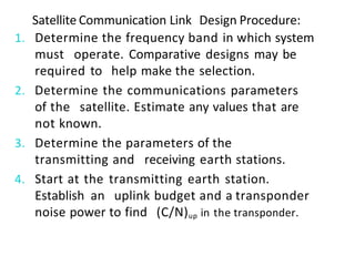
Satellite Communication LinkDesign Procedure:
1. Determine the frequency band in which system
must operate. Comparative designs may be
required to help make the selection.
2. Determine the communications parameters
of the satellite. Estimate any values that are
not known.
3. Determine the parameters of the
transmitting and receiving earth stations.
4. Start at the transmitting earth station.
Establish an uplink budget and a transponder
noise power to find (C/N)up in the transponder.
38.
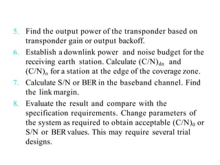
5. Find theoutput power of the transponder based on
transponder gain or output backoff.
6. Establish a downlink power and noise budget for the
receiving earth station. Calculate (C/N)dn and
(C/N)o for a station at the edge of the coverage zone.
7. Calculate S/N or BER in the baseband channel. Find
the link margin.
8. Evaluate the result and compare with the
specification requirements. Change parameters of
the system as required to obtain acceptable (C/N)0 or
S/N or BERvalues. This may require several trial
designs.
39.
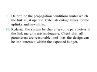
9. Determine thepropagation conditions under which
the link must operate. Calculate outage times for the
uplinks and downlinks.
10. Redesign the system by changing some parameters if
the link margins are inadequate. Check that all
parameters are reasonable, and that the design can
be implemented within the expected budget.


![◻Thus the power received by real antenna with effective
aperture area Ae m2 is
Pr = Pt Gt Ae / 4 πR2 (watts)……..(A)
◻Afundamental relation in antenna theory is gain &
area of an antenna are related by
G = 4π Ae / λ2
◻Substituting above equation in equation (A) gives
Pr = [Pt Gt Gr/ (4 πR / λ )2 ]watts
◻This expression is known as link equation &essential
in calculation of power received in any radio link.
◻The term (4 πR / λ )2 is known as path loss Lp .](https://image.slidesharecdn.com/unit-3satellitelinkdesign-250924132824-b4600931/85/Satellite-communications-UNIT-3-satellitelink-design-pdf-7-320.jpg)

![Design for Specified C/N:
◻ The S/N ratio in the baseband channel of an earth station receiver is
determined by the ratio of the carrier power to the noise power in the IF
amplifier at the input to the demodulator. The noise present in the IF
amplifier comes from many sources. In this analysis of uplink and downlink
we have considered only the receiver thermal noise and noise radiated by
atmospheric gases and rain in the slant path.
◻ When more than one C/N ratio is present in the link, we can add the
individual C/N ratios reciprocally to obtain overall C/N ratio denoted
as (C/N)o
◻ The overall (C/N)o ratio is
(C/N)o = 1/[1/(C/N)1 + 1/(C/N)2 +_ _ _ __]](https://image.slidesharecdn.com/unit-3satellitelinkdesign-250924132824-b4600931/85/Satellite-communications-UNIT-3-satellitelink-design-pdf-35-320.jpg)