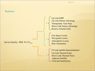
Downloaded 78 times


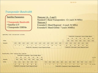
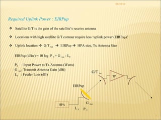
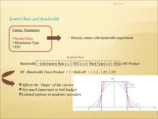
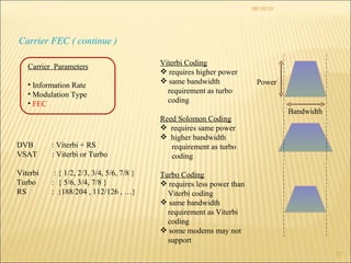
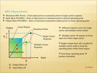
![08/10/10 HPA Sizing Case Study: Determine the HPA size required to uplink one 128kbsp and one 64kbps carriers. Tx antenna size is 2.4m. EIRPup 1 (for 128k) = 45.6dBw EIRPup 2 (for 64k) = 42.6dBw EIRPup Total = 10log[10 (EIRPup1/10) + 10 (EIRPup2/10) ] = 47.4 dBw G Ant = 41.6 dBi (from antenna spec) L F = 1dB (actual loss may be higher need more uplink power) P out = EIRPup Total –G Ant + L F = 6.8 dBw More than one carrier from HPA, needs to back off to avoid intermods. ( see. HPA Characteristic ) OBO hpa = 3dB Saturated output power , P S = P out + OBO hpa = 9.8 dBw Required HPA Size = 10^ (P S /10) = 9.55 Watts HPA G Ant L F P out EIRP up P T](https://image.slidesharecdn.com/linkbudget-12814193956517-phpapp02/85/Link-Budget-8-320.jpg)
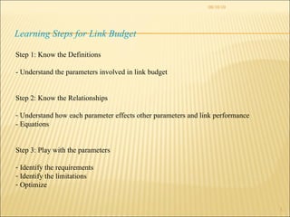
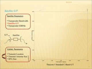
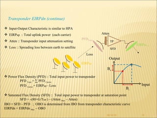
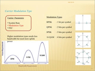
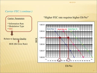
![08/10/10 Transponder EIRPdn EIRPdn Thaicom 5 Standard C-Band EIRPdn Contour [ All standard c-band transponders on T5 have same contour pattern] Downlink Parameters Receive Location(s) Antenna Size (s) Eb/No Threshold Satellite Satellite Parameters Transponder Bandwidth Satellite G/T Transponder EIRPdn](https://image.slidesharecdn.com/linkbudget-12814193956517-phpapp02/85/Link-Budget-9-320.jpg)
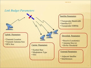
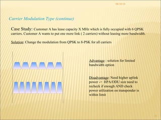
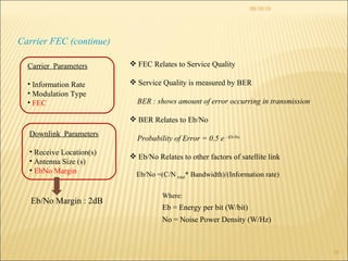
![08/10/10 Carrier EIRPdn Transponder power is shared by all carriers using on the transponder Each carrier must operate within allowable limit of power allocated for its bandwidth Transponder Operation Modes Single Carrier Mode OBO = 0 dB Max Transponder EIRPdn : 40 dBw Allowable EIRPdn per carrier = 40dBW – 0 dB = 40 dBw Two Carriers Mode OBO = 2 dB Max Transponder EIRPdn : 40 dBw – 2dB = 38 dBw Allowable EIRPdn per carrier = 38 dBw – 3dB = 35 dBw Multiple Carriers Mode OBO = 4 dB Max Transponder EIRPdn : 40 dBw – 4dB = 36dBw Allowable EIRPdn per carrier : 10log[(x/36)*{10^((36)/10)}] x : bandwidth (in MHz) of the carrier 36MHz 18MHz 18MHz](https://image.slidesharecdn.com/linkbudget-12814193956517-phpapp02/85/Link-Budget-11-320.jpg)


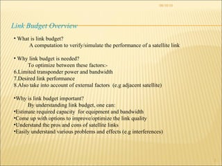
The document discusses link budget analysis for satellite communications. Link budget is used to optimize satellite link performance given limited transponder power and bandwidth. It involves understanding parameters like transponder bandwidth, satellite gain, transmit power, modulation, coding, and receiver sensitivity to estimate required capacity and improve link quality. Key factors that impact the link budget calculation are discussed in detail.


