The document is the operation and service manual for the DustTrak II Aerosol Monitor Models 8530/8531/8532. It describes unpacking the instrument and identifying parts, setting up the instrument by supplying power and connecting accessories, operating the instrument by navigating menus and taking measurements, maintaining the instrument through cleaning and filter replacement, and troubleshooting issues. The manual provides safety information and specifications for the laser-based particulate matter monitor.
Contoh Bagaimana Melakukan Cara Pengambilan Sampel Sampling Air, Langkah-Langkah yang benar Cara Pengambilan Sampel Sampling Air apa itu Sampel Sampling Air
Contoh Bagaimana Melakukan Cara Pengambilan Sampel Sampling Air, Langkah-Langkah yang benar Cara Pengambilan Sampel Sampling Air apa itu Sampel Sampling Air
David Keith Todd_ Larry W Mays - Groundwater hydrology-Wiley (2005).pdfNIKETADAYMA
Groundwater hydrology is the study of water beneath the Earth's surface, specifically within subsurface geological formations. It plays a crucial role in the Earth's hydrological cycle, contributing to the availability of freshwater for various human and environmental needs.
Permen LHK no.70 2016 ttg baku mutu emisi usaha dan atau kegiatan pengolahan ...Rizki Darmawan
Peraturan Menteri Lingkungan Hidup dan Kehutanan Republik Indonesia tentang baku mutu emisi usaha atau kegiatan sampah secara termal yang disahkan tahun 2016.
SNI 09-7118.2-2005 tentang Emisi Gas Buang - Sumber Bergerak - Bagian 2: Cara...Muhamad Imam Khairy
SNI 09-7118.2-2005 tentang Emisi Gas Buang - Sumber Bergerak - Bagian 2: Cara Uji Kendaraan Bermotor Kategori M, N, dan O Berpenggerak Penyalaan Kompresi pada Kondisi Akselerasi Bebas
Neurociencias - Bases neurológicas de la psicología humanaJosé Luis Ayerbe
Relación entre el soporte físico biológico del sistema nervioso y la conducta humana . Un trabajo del Dr. José Luis Ayerbe , parte de los apuntes de la Cátedra de Psicología médica dados en 1983 . Premiado con diploma al mérito académico.
The Hart Scientific 9132 Portable IR Calibrator may be used as a portable instrument or bench
top temperature calibrator for calibrating point IR thermometers. The 9132 is small enough to
use in the field, and accurate enough to use in the lab. Calibrations may be done over a range of
50°C to 500°C (122°F to 932°F). Temperature display and setability resolution of the 9132 is
0.1 degrees.
Foxwell NT630 Plus User’s Manual
>> READ MORE: https://www.obdadvisor.com/foxwell-nt630-plus-review/
Here is a detailed review of the Foxwell NT630 scan tool:
- Display
- Software
- Features and functions
- Compatibility
- Pros and cons
Check it out to get the REVIEW and some NOTES about using this scanner based on my own experience.
This is the user manual of Foxwell NT630 Pro.
>> READ MORE: https://www.obdadvisor.com/foxwell-nt630-plus-review/
Here is a detailed review of the scan tool based on my own experience, including:
- Display
- Software
- Features and functions
- Compatibility
- Pros and cons
Check it out to get the REVIEW and some NOTES about using this scanner.
How to use Foxwell CRD700 diagital pressure tester.Obdexpress.co.uk
Here's Foxwell CRD700 diagital pressure tester costomer manual.Top 9 Reasons to Get CRD700:1. Checks high-pressure pump of common rail systems.2. Dynamic test: measures actual pressure in common rail circuit with engine running.3. Maximum pressure test: checks high-pressure pump and compares with manufacturer's values.CRD700 stores maximum pressure value.4. Environmental pressure adjustment
.5. Wireless data transmitter sends test results to computer for review and printing.6. Automatic engine start from tester.7. Support Multilingual: English,French,Spanish,Netherlands,German,Hungarian,Portuguese,Italian.8. It is constructed to resist impact and damage in the tough workshop environment. A rubberized sleeve protects your investment. The secure fit, extra corner padding and screen protector ensure your scan tool will be around for a long time.
It's from the OBD2 TOOL website:www.foxwellshop.com.hope to help you.
Foxwell Battery Tester BT780 User ManualTim Miller
This is the user manual of Foxwell Battery Tester BT780.
>> READ MORE: https://www.obdadvisor.com/best-battery-tester-review/
Here is a detailed review of the tester based on my own experience, including:
- Compatibility
- Features and Functions
- Pros and Cons
Check it out to get the REVIEW and some NOTES about using the tool.
This is the user manual of Foxwell NT630.
>> READ MORE: https://www.obdadvisor.com/foxwell-nt630-plus-review/
Here is a detailed review of the scan tool based on my own experience, including:
- Display
- Software
- Features and functions
- Compatibility
- Pros and cons
Check it out to get the REVIEW and some NOTES about using this scanner.
This is the user manual of Foxwell NT650.
>> READ MORE: https://www.obdadvisor.com/foxwell-nt650-review/
Here is a detailed review of the scan tool based on my own experience, including:
- Display
- Software
- Features and functions
- Compatibility
- Pros and cons
Check it out to get the REVIEW and some NOTES about using this scanner.
Foxwell i70 Diagnostic System User Manual OBDII365OBD365
Foxwell i70 Pro delivers faster and smarter diagnosis for workshops and technicians.
http://www.obdii365.com/wholesale/foxwell-i70-pro-premier-diagnostic-tool.html
With IP67 rated waterproof, dustproof and shockproof design, i70Pro can resist the impact and the damage of even the toughest workshop environment and road tests. Through hardware and software upgrades, technical staff can now approach problems with greater speed and accuracy, and produce comprehensive, professional reports.
Natural farming @ Dr. Siddhartha S. Jena.pptxsidjena70
A brief about organic farming/ Natural farming/ Zero budget natural farming/ Subash Palekar Natural farming which keeps us and environment safe and healthy. Next gen Agricultural practices of chemical free farming.
Artificial Reefs by Kuddle Life Foundation - May 2024punit537210
Situated in Pondicherry, India, Kuddle Life Foundation is a charitable, non-profit and non-governmental organization (NGO) dedicated to improving the living standards of coastal communities and simultaneously placing a strong emphasis on the protection of marine ecosystems.
One of the key areas we work in is Artificial Reefs. This presentation captures our journey so far and our learnings. We hope you get as excited about marine conservation and artificial reefs as we are.
Please visit our website: https://kuddlelife.org
Our Instagram channel:
@kuddlelifefoundation
Our Linkedin Page:
https://www.linkedin.com/company/kuddlelifefoundation/
and write to us if you have any questions:
info@kuddlelife.org
"Understanding the Carbon Cycle: Processes, Human Impacts, and Strategies for...MMariSelvam4
The carbon cycle is a critical component of Earth's environmental system, governing the movement and transformation of carbon through various reservoirs, including the atmosphere, oceans, soil, and living organisms. This complex cycle involves several key processes such as photosynthesis, respiration, decomposition, and carbon sequestration, each contributing to the regulation of carbon levels on the planet.
Human activities, particularly fossil fuel combustion and deforestation, have significantly altered the natural carbon cycle, leading to increased atmospheric carbon dioxide concentrations and driving climate change. Understanding the intricacies of the carbon cycle is essential for assessing the impacts of these changes and developing effective mitigation strategies.
By studying the carbon cycle, scientists can identify carbon sources and sinks, measure carbon fluxes, and predict future trends. This knowledge is crucial for crafting policies aimed at reducing carbon emissions, enhancing carbon storage, and promoting sustainable practices. The carbon cycle's interplay with climate systems, ecosystems, and human activities underscores its importance in maintaining a stable and healthy planet.
In-depth exploration of the carbon cycle reveals the delicate balance required to sustain life and the urgent need to address anthropogenic influences. Through research, education, and policy, we can work towards restoring equilibrium in the carbon cycle and ensuring a sustainable future for generations to come.
Willie Nelson Net Worth: A Journey Through Music, Movies, and Business Venturesgreendigital
Willie Nelson is a name that resonates within the world of music and entertainment. Known for his unique voice, and masterful guitar skills. and an extraordinary career spanning several decades. Nelson has become a legend in the country music scene. But, his influence extends far beyond the realm of music. with ventures in acting, writing, activism, and business. This comprehensive article delves into Willie Nelson net worth. exploring the various facets of his career that have contributed to his large fortune.
Follow us on: Pinterest
Introduction
Willie Nelson net worth is a testament to his enduring influence and success in many fields. Born on April 29, 1933, in Abbott, Texas. Nelson's journey from a humble beginning to becoming one of the most iconic figures in American music is nothing short of inspirational. His net worth, which estimated to be around $25 million as of 2024. reflects a career that is as diverse as it is prolific.
Early Life and Musical Beginnings
Humble Origins
Willie Hugh Nelson was born during the Great Depression. a time of significant economic hardship in the United States. Raised by his grandparents. Nelson found solace and inspiration in music from an early age. His grandmother taught him to play the guitar. setting the stage for what would become an illustrious career.
First Steps in Music
Nelson's initial foray into the music industry was fraught with challenges. He moved to Nashville, Tennessee, to pursue his dreams, but success did not come . Working as a songwriter, Nelson penned hits for other artists. which helped him gain a foothold in the competitive music scene. His songwriting skills contributed to his early earnings. laying the foundation for his net worth.
Rise to Stardom
Breakthrough Albums
The 1970s marked a turning point in Willie Nelson's career. His albums "Shotgun Willie" (1973), "Red Headed Stranger" (1975). and "Stardust" (1978) received critical acclaim and commercial success. These albums not only solidified his position in the country music genre. but also introduced his music to a broader audience. The success of these albums played a crucial role in boosting Willie Nelson net worth.
Iconic Songs
Willie Nelson net worth is also attributed to his extensive catalog of hit songs. Tracks like "Blue Eyes Crying in the Rain," "On the Road Again," and "Always on My Mind" have become timeless classics. These songs have not only earned Nelson large royalties but have also ensured his continued relevance in the music industry.
Acting and Film Career
Hollywood Ventures
In addition to his music career, Willie Nelson has also made a mark in Hollywood. His distinctive personality and on-screen presence have landed him roles in several films and television shows. Notable appearances include roles in "The Electric Horseman" (1979), "Honeysuckle Rose" (1980), and "Barbarosa" (1982). These acting gigs have added a significant amount to Willie Nelson net worth.
Television Appearances
Nelson's char
UNDERSTANDING WHAT GREEN WASHING IS!.pdfJulietMogola
Many companies today use green washing to lure the public into thinking they are conserving the environment but in real sense they are doing more harm. There have been such several cases from very big companies here in Kenya and also globally. This ranges from various sectors from manufacturing and goes to consumer products. Educating people on greenwashing will enable people to make better choices based on their analysis and not on what they see on marketing sites.
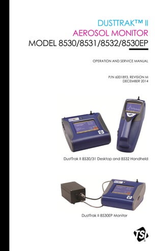
1. DUSTTRAK™ II
AEROSOL MONITOR
MODEL 8530/8531/8532/8530EP
OPERATION AND SERVICE MANUAL
P/N 6001893, REVISION M
DECEMBER 2014
DustTrak II 8530/31 Desktop and 8532 Handheld
DustTrak II 8530EP Monitor
4. ii
INJURIES, OR DAMAGES CONCERNING THE GOODS (INCLUDING CLAIMS BASED
ON CONTRACT, NEGLIGENCE, TORT, STRICT LIABILITY OR OTHERWISE) SHALL
BE THE RETURN OF GOODS TO SELLER AND THE REFUND OF THE PURCHASE
PRICE, OR, AT THE OPTION OF SELLER, THE REPAIR OR REPLACEMENT OF THE
GOODS. IN THE CASE OF SOFTWARE, SELLER WILL REPAIR OR REPLACE
DEFECTIVE SOFTWARE OR IF UNABLE TO DO SO, WILL REFUND THE PURCHASE
PRICE OF THE SOFTWARE. IN NO EVENT SHALL SELLER BE LIABLE FOR LOST
PROFITS, BUSINESS INTERRUPTION OR ANY SPECIAL, INDIRECT,
CONSEQUENTIAL OR INCIDENTAL DAMAGES. SELLER SHALL NOT BE
RESPONSIBLE FOR INSTALLATION, DISMANTLING OR REINSTALLATION COSTS
OR CHARGES. No Action, regardless of form, may be brought against Seller more than 12
months after a cause of action has accrued. The goods returned under warranty to Seller's
factory shall be at Buyer's risk of loss, and will be returned, if at all, at Seller's risk of loss.
Buyer and all users are deemed to have accepted this LIMITATION OF WARRANTY AND
LIABILITY, which contains the complete and exclusive limited warranty of Seller. This
LIMITATION OF WARRANTY AND LIABILITY may not be amended, modified or its terms
waived, except by writing signed by an Officer of Seller.
Service Policy
Knowing that inoperative or defective instruments are as detrimental to TSI as they are
to our customers, our service policy is designed to give prompt attention to any
problems. If any malfunction is discovered, please contact your nearest sales office or
representative, or call TSI's Customer Service departmentat (800) 874-2811 (USA) or
(001 651) 490-2811 (International) or visit www.tsi.com.
5. iii
CONTENTS
SAFETY INFORMATION ............................................................................... V
Laser Safety.................................................................................................v
Labels ......................................................................................................... vi
Description of Caution/Warning Symbols................................................... vii
Caution ................................................................................................... vii
Warning .................................................................................................. vii
Caution and Warning Symbols................................................................... vii
Reusing and Recycling............................................................................... vii
CHAPTER 1 UNPACKING AND PARTS IDENTIFICATION.........................1
Unpacking the DustTrak II Aerosol Monitor ..................................................2
Optional Accessories................................................................................7
Parts Identification for the DustTrak II Desktop Aerosol Monitor
Models 8530/8531 ....................................................................................8
Parts Identification for the DustTrak II Desktop Aerosol Monitor
Model 8530EP..........................................................................................9
External Pump Module (8530EP only) .........................................................9
Parts Identification for the DustTrak II Handheld Aerosol Monitor
Model 8532.............................................................................................10
CHAPTER 2 SETTING UP..........................................................................11
Supplying Power to the DustTrak II Aerosol Monitor..................................11
Installing the Batteries in Model 8530/8531/8530EP Desktop ................11
Installing the Batteries in Model 8532 Handheld.....................................11
Connecting the External Pump to DustTrak Model 8530EP ...................12
Using the AC Adapter to Run Instrument................................................14
Battery Charging.....................................................................................14
Inlet Cap .................................................................................................14
Size-Selective Impactors ........................................................................15
Dorr-Oliver Cyclone ................................................................................16
Instrument Setup........................................................................................16
Connecting to the Computer...................................................................16
Installing TrakPro
TM
Data Analysis Software ..........................................16
Connecting Analog/Alarm Output ...........................................................17
Wiring the Analog Output ...........................................................................18
Wiring the Alarm.........................................................................................18
CHAPTER 3 OPERATION ..........................................................................19
Getting Started...........................................................................................19
For Model DustTrak 8530EP only ..............................................................19
Setup Menu................................................................................................22
Zero Cal..................................................................................................23
Flow Cal..................................................................................................24
User Cal..................................................................................................25
Alarm ......................................................................................................30
Analog ....................................................................................................32
Settings ..................................................................................................33
Run Mode...............................................................................................35
Survey Mode ..........................................................................................36
6. iv
Manual Mode.......................................................................................... 37
Log Mode (1–5)...................................................................................... 38
Taking Mass Concentration Measurements............................................... 39
Screen Regions...................................................................................... 40
Stats....................................................................................................... 41
Graphing ................................................................................................ 41
Viewing Data.............................................................................................. 43
Title Bar ..................................................................................................... 44
CHAPTER 4 MAINTENANCE..................................................................... 45
Maintenance Schedule .............................................................................. 45
Zeroing Instrument..................................................................................... 46
Cleaning the Inlet....................................................................................... 46
Cleaning and Oiling Impactors................................................................... 47
Replacing the Internal Filters ..................................................................... 48
Replacing the Filters in the External Pump Module ................................... 51
Storage Precautions .................................................................................. 52
CHAPTER 5 TROUBLESHOOTING........................................................... 53
APPENDIX A SPECIFICATIONS............................................................... 59
APPENDIX B ZERO MODULE .................................................................. 61
INDEX ........................................................................................................... 63
These Application Notes can also be found on TSI’s web site:
http://www.tsi.com
EXPMN-001 DustTrak II Theory of Operation.pdf
EXPMN-003 DustTrak II Impactor.pdf
7. v
Safety Information
I M P O R T A N T
There are no user serviceable parts inside the instrument. Refer all repair
and maintenance to a qualified factory-authorized technician. All
maintenance and repair information in this manual is included for use by a
qualified factory-authorized technician.
Laser Safety
The Model 8530/8531/8532 DustTrak II monitor is a Class I laser-based
instrument.
During normal operation, you will not be exposed to laser radiation.
Precaution should be taken to avoid exposure to hazardous radiation in
the form of intense, focused, visible light.
Exposure to this light may cause blindness.
Take these precautions:
DO NOT remove any parts from the DustTrak II monitor unless you are
specifically told to do so in this manual
DO NOT remove the housing or covers. There are no serviceable
components inside the housing.
W A R N I N G
The use of controls, adjustments, or procedures other
than those specified in this manual may result in exposure
to hazardous optical radiation.
W A R N I N G
There are no user-serviceable parts inside this
instrument. The instrument should only be opened by TSI
or a TSI approved service technician.
W A R N I N G
If the DustTrak monitor is used in a manner not specified
by the manufacturer, the protection provided by the
equipment may be impaired.
When operated according to the manufacturer’s instruction, this device is a
Class I laser product as defined by U.S. Department of Health and Human
Services standards under the Radiation Control for Health and Safety Act of
1968. A certification and identification label like the one shown below is
affixed to each instrument.
8. vi
Labels
Advisory labels and identification labels are attached to the instrument.
1. Serial Number Label
(bottom)
2. Laser Radiation Label
(internal)
DANGER!
VISIBLE LASER RADIATION WHEN
OPEN. AVOID DIRECT EXPOSURE
TO BEAM
WARNING: NO USER SERVICABLE
PARTS INSIDE. REFER SERVICING
TO QUALIFIED PERSONNEL
3. Battery label
or
4. European symbol for
non-disposable item.
Item must be recycled.
9. vii
Description of Caution/Warning Symbols
Appropriate caution/warning statements are used throughout the manual and
on the instrument that require you to take cautionary measures when working
with the instrument.
Caution
C a u t i o n
Failure to follow the procedures prescribed in this
manual might result in irreparable equipment damage.
Important information about the operation and
maintenance of this instrument is included in this
manual.
Warning
W A R N I N G
Warning means that unsafe use of the instrument could
result in serious injury to you or cause damage to the
instrument. Follow the procedures prescribed.
Caution and Warning Symbols
The following symbols may accompany cautions and warnings to indicate the
nature and consequences of hazards:
Warns that the instrument contains a laser and that
important information about its safe operation and
maintenance is included in the manual.
Warns that the instrument is susceptible to electro-static
discharge (ESD) and ESD protection should be followed
to avoid damage.
Indicates the connector is connected to earth ground and
cabinet ground.
Reusing and Recycling
As part of TSI Incorporated’s effort to have a minimal
negative impact on the communities in which its products
are manufactured and used:
Do not dispose of used batteries in the trash.
Follow local environmental requirements for
battery recycling.
If instrument becomes obsolete, return to TSI for
disassembly and recycling.
11. 1
Chapter 1
Unpacking and Parts Identification
Carefully unpack the Model 8530/8531/8532 DustTrak™ II Aerosol Monitor
from the shipping container. Use the tables and illustrations below to make
certain that there are no missing components. Contact TSI immediately if
anything is missing or damaged.
Note
If you purchased a DustTrak II Model 8530-NA (no accessories)
Aerosol Monitor, it only comes with the following items:
DustTrak II Model 8530 Aerosol Monitor
Operations manual
TrakPro™ Data Analysis Software CD
One-year calibration certificate
Service paperwork
2-year warranty
All accessories for the DustTrak II Model 8530 Aerosol Monitor
are sold separately. Contact TSI at (800) 874-2811 for
information on accessories and how to purchase them through a
TSI sales representative.
(continued on next page)
12. Chapter 12
Unpacking the DustTrak II Aerosol Monitor
Compare all the components you received with those listed in the table below.
If any parts are missing, contact TSI.
Item Qty
Part
Number Description
or
1 8530
8531
8532
Desktop II
Desktop II HC
Handheld II
1 801670
801669
Desktop II
Carrying Case
Handheld II
Carrying Case
1 1090014 Data Analysis
Software CD-
ROM
1 800663 Zero Filter
13. Unpacking and Parts Identification 3
Item Qty
Part
Number Description
or
1 801680
801681
6600 mAH
Lithium Ion
Rechargeable
Battery
(Desktop)
Rechargeable
lithium ion
battery
(Handheld)
1 1303740 USB cable
1 801652 Analog/alarm
output cable
(Desktop models
only)
1 6001893 Operation and
Service Manual
1 N/A Calibration
Certificate
14. Chapter 14
Item Qty
Part
Number Description
1 801688 Conductive
Tubing
1 801668 Filter removal
tool (Spanner
Driver)
4
2
1
801673 Spare Internal
Filter Elements
Desktop Model
Only
37-mm filter
includes:
Filter body top
Filter body
bottom
Mesh screen
Comes with
37-mm cartridge
opening tool
8 801666 Spare Internal
Filters
Handheld Model
Only
15. Unpacking and Parts Identification 5
Item Qty
Part
Number Description
1 801667 Impactor Kit
PM2.5 assembled
Top
Bottom
Impaction
Plate
PM1.0 Top
PM4.0 Top
PM10 Top
Extra Impaction
Plate
1 801691 Dorr-Oliver
Cyclone
1 801692
801694
Power Supply –
Desktop
Power Supply –
Handheld
2 N/A Stylus
When shipped,
one stylus will be
in the accessory
bag, the second
stylus attached
to instrument.
1 3012094 Screwdriver,
dual ended.
(For Handheld
Models only)
16. Chapter 16
Item Qty
Part
Number Description
1 801674 Impactor Oil
2 801698 Inlet cap
When shipped,
one inlet will be
in the accessory
bag, the second
inlet attached to
instrument.
1 801675 External Pump
Kit for 8530EP
only
1 801797 External Pump
Power Cable (to
DustTrak
monitor) for
8530EP only
1 801798 External Pump
Flow Tube (to
DustTrak
monitor) for
8530EP only
1 Exhaust Adapter,
DustTrak monitor
for 8530EP only
17. Unpacking and Parts Identification 7
Optional Accessories
The following photos and table list optional accessories. If you ordered
optional accessories, make certain they have been received and are in
working order.
Accessories Qty
Part
Number Description
1 801675 External Pump
Kit
2 801795 DustTrak II/DRX
External Pump
Service Kit for
8530EP only.
Contains two
filters for
External Pump
1 801685 Battery Charger,
2-Bay, Battery
801680 for
Desktop DustTrak
monitor
1 801686 Battery Charger,
Battery 801681
for Handheld
DustTrak monitor
18. Chapter 18
Parts Identification for the DustTrak II Desktop
Aerosol Monitor Models 8530/8531
Touchscreen
On/Off
Inlet
Stylus
Power
Analog/Alarm
Output
USB Host
USB Device
Ethernet
Filter Access
Zero Module
Connector Battery Access
Figure 1-1: Features on Desktop Model 8530/8531
19. Unpacking and Parts Identification 9
Parts Identification for the DustTrak II Desktop
Aerosol Monitor Model 8530EP
Exhaust Adapter External Pump
External Pump
Power Connection
External Pump
Flow Tubing
External Pump Module (8530EP only)
Pump Suction End
Pump Exhaust End
Pump Power Connection
User Replaceable HEPA Filters
Pump
Figure 1-2: Features on Desktop Model 8530EP
20. Chapter 110
Parts Identification for the DustTrak II Handheld
Aerosol Monitor Model 8532
On/Off
Inlet
Stylus
Touchscreen
Port Cover
Power
USB Device
USB Host
Filter Access
Battery Access
(Screw Lockdown)
Figure 1-3: Features on Handheld Model
21. 11
Chapter 2
Setting Up
Supplying Power to the DustTrak II Aerosol Monitor
The DustTrak II Aerosol Monitor must be powered by either batteries or using
the external AC adapter.
W A R N I N G
The instrument has been design to be used with batteries
supplied by TSI. Do not use a substitute.
Disposing of old batteries must be recycled in accordance
with the local environmental regulations.
W A R N I N G
Do not use non-rechargeable batteries in this instrument.
Fire, explosions, or other hazards may result.
Installing the Batteries in Model 8530/8531/8530EP Desktop
Remove the battery cover and slide one or two batteries into the battery slots.
A single battery can be put into either slot. Orient the batteries with the label
side facing up (see Figure 2-1).
Figure 2-1: Batteries into Desktop Unit
Installing the Batteries in Model 8532 Handheld
Remove the battery cover by loosening captured screw on the bottom of the
unit. Orient battery with brass connectors facing forward. Insert battery into
cavity and slide forward to engage into pins. Replace the battery cover and
secure by tightening screw (see Figure 2-2).
22. Chapter 212
Figure 2-2: Batteries into Handheld Unit
Connecting the External Pump to DustTrak Model 8530EP
The Model 8530EP is a Desktop DustTrak monitor with an external pump.
This DustTrak has no internal pump and will not work with any other external
pump other than the one provided by TSI (p/n 801675). The Model 8530EP is
intended for applications where the DustTrak is operated continuously over
extended periods (several days to months) under wide temperature
fluctuations (0 to 50°C). The external pump is designed to be more robust for
24/7 operation of the DustTrak monitor and is warranted to operate
continuously for one full year or 8760 hours. The Model 8530EP is ideal for
fugitive dust monitoring.
The pump and the DustTrak monitor come separately and require assembly.
Follow the steps below to connect the pump with the Model 8530EP DustTrak
monitor.
W A R N I N G
Turn the DustTrak monitor OFF before connecting the
external pump. Turn the DustTrak monitor ON only after
connecting the External Module.
1. Connect the pump end of the quick connect to the pump module (see
Figure 2-3).
Figure 2-3: Connect Pump End of Quick Connect to Pump Module
23. Setting Up 13
2. Likewise, plug one end of the power connector to the pump module as
shown above. Turn the power connector until it clicks and locks in place.
This prevents the connector from disconnecting due to vibration or
movement.
3. Connect the exhaust adapter to the exhaust of the DustTrak monitor (see
Figure 2-4).
Figure 2-4: Connect Exhaust Adapter to Exhaust of DustTrak Monitor
4. Connect the other end of the flow tubing to the exhaust adapter of the
DustTrak monitor.
5. Connect the other end of the power connector to the DustTrak monitor
(see Figure 2-5).
Figure 2-5: Connect Power Connector to DustTrak Monitor
W A R N I N G
The Pump module design does not allow for installation
outdoors without any protection from the elements. Always
operate it within an enclosure.
The DustTrak external pump module does not require an A/C adapter. It is
always powered off the DustTrak monitor.
24. Chapter 214
Notes
1. The power connector and the flow quick connect “click” when
securely connected. The power connector must be rotated
clockwise past the locking pin.
2. Do not hot-plug the External Pump Module when the
DustTrak monitor is turned ON. Always connect the External
Pump module first and then turn the DustTrak monitor ON.
3. TSI recommends that the DustTrak monitor with the external
pump be operated in the Model 8535 Environmental
Enclosure.
4. TSI recommends that the pump module be operated when
mounted on its feet and avoid operating at other orientations
as much as possible.
5. Pump module and the DustTrak monitor should be at the
same electrical potential.
6. The additional port on the external pump module is where the
pump exhausts the flow. For applications where the DustTrak
monitor is sampling from a chamber or a duct at pressures
significantly different from the ambient, TSI recommends
plumbing the exhaust of the external pump back in to the
chamber/duct.
Using the AC Adapter to Run Instrument
The AC adapter allows you to power the DustTrak monitor from an AC wall
outlet. When using the AC adapter, the batteries (if installed) are bypassed.
Battery Charging
This instrument will charge the Lithium Ion battery packs. Insert the batteries
into the battery compartment, plug the instrument into AC power, and turn the
instrument on. Batteries will charge only when the instrument is on and in
stand-by mode. Batteries will not charge if the instrument is turned off or is
actively taken measurements. Charging will stop when the batteries are fully
charged.
W A R N I N G
When Charging Battery the ambient temp must not
exceed 42°C.
Inlet Cap
When using the DustTrak monitor to sample environmental air, the inlet cap
should be put over the instrument. This cap will keep large objects from
dropping into and plugging the inlet. The cap will also keep direct light from
shinning into the chamber and skewing the results.
The inlet cap can simply be pressed onto the instruments inlet.
25. Setting Up 15
Figure 2-6: Putting on Inlet Cap
Size-Selective Impactors
Size-selective impactors can be attached to the inlet of the DustTrak II
instruments. Size-selective impactors can be used to pre-condition the size
range of the particles entering the instrument. PM1, PM2.5, PM4 (Respirable)
and PM10 impactors are available. The instrument must run at the factory
default setting of 3.0 L/min for the impactors to achieve the correct cut
points.
The size-selective impactor is composed of three parts; the cap, impaction
plate and bottom. Selection of the cap will determine cut size of the impactor.
Each cap is labeled with the particle cut size (1 µm, 2.5 µm, 4.0 µm or
10 µm). The same impaction plate and bottom are used on all impactor sizes.
Impaction Plate
Cap (1 µm,
2.5 µm, 4 µm
or 10 µm)
Bottom
Figure 2-7: Size-Selective Impactor
The impactor assembly is attached to the instrument in place of the inlet cap.
The inlet cap does not need to be used if an impactor is being used. See
Chapter 4, "Maintenance," for instructions on how to add oil to the
impaction plate.
26. Chapter 216
Dorr-Oliver Cyclone
A Dorr-Oliver cyclone is shipped with the instrument. The Dorr-Oliver cyclone
removes particles over 4.0 µm in size. The Dorr-Oliver cyclone is attached to
the instrument by sliding the cyclone clip over the protruding catch. The tube
from the Dorr-Oliver cyclone needs to be routed to the inlet of the instrument.
Figure 2-8: Installing Door-Oliver Cyclone
Do not use Inlet attachments (impactors or inlet cap) when using the Dorr-
Oliver Cyclone. The instrument flow rate must be changed to 1.7 L/min
when using the Dorr-Oliver Cyclone in order to achieve a 4 µm
(respirable) cut-point. See the Flow Cal instructions in the Operations
chapter for instructions on how to change the instruments flow rate.
Instrument Setup
The DustTrak II monitor can be connected to a computer to download data
and upload sampling programs.
Connecting to the Computer
Connect the USB host port of a Microsoft Windows®-based computer to the
USB device port on the side of the DustTrak monitor.
Installing TrakProTM
Data Analysis Software
TrakPro software can preprogram the DustTrak monitor, download data, view
and create raw data and statistical reports, create graphs, and combine
graphs with data from other TSI instruments that use TrakPro software. The
following sections describe how to install the software and set up the
computer.
Note
To use TrakPro software with the DustTrak Aerosol Monitor, the
PC must be running Microsoft Windows
®
and the computer must
have an available Universal Serial Bus (USB) port.
®
Windows is a registered trademark of Microsoft Corporation.
27. Setting Up 17
1. Insert the TrakPro Data Analysis Software CD into the CD-ROM drive.
The install screen starts automatically.
Note
If the software does not start automatically after a few minutes,
manually run the program listed on the label of the CD using the
Run command on the Windows Start Menu.
2. Follow the directions to install TrakPro software.
TrakPro software contains a comprehensive installation guide. TSI
recommends printing out this guide prior to starting the TrakPro software
installation on your computer, so it may be consulted during the installation.
The TrakPro Software manual is located in the “Help” file in TrakPro
software. There is no separately printed TrakPro Data Analysis software
manual.
Connecting Analog/Alarm Output
The Analog/Alarm Output Cable plugs into the alarm connection on the side
of the instrument. This feature is on the desktop models (8530/8531) only.
The cable contains a 4-pin, mini-DIN connector. The pin-outs for the
connector and the wiring for the cable are shown below.
Alarm Positive (+)
Alarm Ground (–)
Analog Output (+)
Analog Ground (–)
4-pin miniDIN connector
Cable Wiring Diagram
Brown Wire Analog Ground
Orange Wire Analog Out
Red Wire Alarm (+)
White Wire Alarm (-)
Black Wire Shield
Figure 2-9: Cable Wiring Diagram
®
Microsoft and Windows are registered trademarks of Microsoft Corporation.
28. Chapter 218
Wiring the Analog Output
System specifications:
Output voltage: 0 to 5 VDC. With a maximum output of 15 mA.
Output Current 4 mA to 20 mA with a maximum load impendence of
250 ohms.
Correct polarity must be observed (see pin-outs above).
The output cable supplied by TSI (part no. 801652) is labeled with the pin-out
wiring diagram. Additional equipment may be needed for making connections
to the system that TSI does not supply. It is your responsibility to specify and
supply all additional equipment.
Wiring the Alarm
System specifications:
Maximum voltage: 15 VDC (DO NOT USE AC POWER)
Maximum current: 1 Amp
Correct polarity must be observed (see pin-outs above)
The alarm switch, located inside the DustTrak monitor must be located
on the ground side of the alarm system.
W A R N I N G
The DustTrak monitor Alarm Output function should not be used
to detect hazardous conditions or to provide an alarm for
protecting human life, health or safety.
C a u t i o n
The alarm switch must not be wired to AC power! Failure to
install the user alarm properly could damage the DustTrak
instrument and/or void the instrument warranty! Please read and
follow all instructions before wiring or operating the user alarm.
W A R N I N G
When connected to the analog out and alarm out connector,
you must use safety certified equipment and/or power sources.
29. 19
Chapter 3
Operation
Getting Started
The START UP screen is displayed initially when the instrument is turned on,
following the initial TSI logo splash screen.
Use a stylus or fingertip, touch the “buttons” on the screen to activate different
menus.
For Model DustTrak 8530EP only
W A R N I N G
Always setup and operate the DustTrak monitor with External
Pump Module with the External Pump Module connected to the
DustTrak monitor. Failure to do so will result in communication
errors.
30. Chapter 320
Communication errors take place under four different scenarios as follows:
1. When the unit is idle and is not connected to the External Pump Module,
a warning displays on the Main screen.
Note
“No Pump is Connected” is a sticky error. Even after the warning
message, if the External Pump Module is connected to the
DustTrak, the error will not disappear until the screen is
refreshed. Refresh the screen by going into a different menu and
returning to the Main menu.
2. When the unit is not connected to the External Pump Module and an
attempt is made to start a run by selecting “Start”, an error appears on
the Main screen.
31. Operation 21
3. If the pump is not connected while attempting to perform a Zero Cal, an
error appears on the Setup screen.
4. If the pump is not connected while attempting to perform a Flow Cal, an
error appears on the Setup screen.
32. Chapter 322
Setup Menu
Pressing Setup activates the Setup Menu touchscreen buttons along the left
edge of the screen. Setup is not accessible when the instrument is sampling.
The main screen of the Setup screen displays the following information:
Serial Number The instruments serial number.
Model Number The instruments model number.
Firmware Version Instruments current version of firmware.
Calibration Date Date of the last factory calibration.
Pump Run Time Pump running time in hours.
Cum Mass Conc Amount of mass run through instrument over life.
Cum Filter Conc Amount of mass run through instrument since last
filter change.
Filter Time Date of last filter change.
33. Operation 23
Zero Cal
Run Zero Cal the first time the instrument is used and repeat prior to every
use. Zero Cal requires that the zero filter be attached prior to running. Zero
Cal must also be performed if the unit is reading negative concentrations. It is
not possible for the DustTrak to read negative concentrations. Negative
concentrations are a symptom of zero drift.
Never perform a zero cal without attaching a zero filter.
1. Press Zero Cal Button
2. Attach Zero Filter
3. Press the Start button to start Zeroing process.
4. A count-down clock will appear indicating the time remaining. The screen
with indicate “Zero Cal Complete” when done.
Remove filter after zeroing has been completed. The instrument is now zero
calibrated and ready for use.
34. Chapter 324
Flow Cal
Run Flow Cal to change the flow set point. The flow set point is factory set to
3 L/min total flow. 2 L/min of the total flow is measured aerosol flow. 1 L/min
of total flow is split off, filtered, and used for sheath flow. There is an internal
P flowmeter in the DustTrak II instrument that controls flow rate to ±5% if
factory setpoint. TSI recommends checking the flows with an external flow
reference meter, especially when collecting data. The pump will automatically
start when entering the Flow Cal screen.
1. Attach a flow calibrator (reference flow meter) to inlet port. You may use
a bubble buret, mass flow meter, dry piston or rotameter as flow
measurement devices.
2. Move the arrows up or down to achieve desired flow on the reference
flowmeter. Each up or down arrow will change the flow about 1%. Allow
time between button presses to let pump change to the new flow rate.
Select Save once the desired flow rate is achieved. Select Undo to
return to the factory set point.
Note
The flow rate can be adjusted from approximately 1.5 to
4.0 L/min. For Model 8533/8534, the FlowCal feature allows you
to re-adjust the flow rate to 3.0 L/min. While the flow rate for
Model 8533/8534 is fixed at 3.0 L/min, the flow rate for Model
8530/8532 can be changed. This allows for the use of other size
selective inlets like cyclones or impactors with Model 8530/8532.
No size-selective inlets should be installed on the inlet of
Model 8533/8534 during its normal operation.
35. Operation 25
User Cal
User Cal allows you to store and use 10 different calibration factors. In
addition, there are two factory defaults, one is the “Ambient Cal” and the other
is the “Factory Cal”. The “Ambient Cal” is appropriate for outdoor ambient
dust or fugitive dust monitoring. The “Factory Cal” is the calibration to ISO
12103-1, A1 Arizona test dust for which a calibration certificate is provided
with the instrument. The “Factory Cal” is appropriate for most workplace
aerosol monitoring. The currently active user calibration is highlighted with an
asterisk “*”.
Four variables can be set for each user calibration.
36. Chapter 326
Name User can rename calibration to a description name.
Photometric Changes the factory calibration of particle signal,
based on Arizona Road Dust, to actual aerosol being
measured. See below for sets to set this calibration.
Size Corr Changes the factory calibration of the particle
distribution, based on Arizona Road Dust, to actual
aerosol being measured. See below for sets to set
this calibration.
User Cal [on,off] Selecting On will activate current user calibration and
deactivate the previously selected user calibration.
Taking a Gravimetric Sample Using the DustTrak Monitor
When sampling with the DustTrak monitor, you can simultaneously take a
gravimetric sample either for custom calibration of the DustTrak monitor or for
collecting the sample on to the gravimetric filter downstream of the DustTrak
monitor without a need for additional gravimetric sampling pump and filter
assembly. To accomplish this, follow the instructions given below:
1. Setup the DustTrak monitor to sample how long you want the sample run
time to be. The following example shows a sample for 8 hours.
2. Under RunMode menu, put the instrument in Manual Log (Manual
Logging is reviewed later in this section), which will enable you to start
and stop the pump at any time you choose.
3. Set the logging interval. One minute (i.e., “01:00”) is a good choice.
4. Make sure you have a preweighed 37-mm gravimetric filter cassette
loaded into the DustTrak monitor. See Chapter 4, “Replacing the Internal
Filters” on how to access the filter (see figure 4-8) and replace it.
Note
Use only the conductive plastic filter cassette holder (SKC
Part# 225-308).
5. Under the Setup Menu, make sure the DustTrak monitor is set to the
desired flow rate. For DustTrak II Models 8530 and 8531, the flows can
be varied from 1.7 to 4 L/min for use with various inlet conditioners. For
DustTrak DRX Model 8533, the flow cannot be changed. The flows for
DustTrak II monitor can be changed by changing the default flow
calibration setpoint from 1.0 to any value between 0.5 to 1.5 in the span
adjustment. An external flowmeter is needed to measure the total flow.
Flow can be changed by clicking on the UP or DOWN arrow keys shown
below:
37. Operation 27
6. Conduct a preflow calibration on the DustTrak monitor using the same
kind of sample media you will sample with. Now, attach the sample
media you intend to sample with and start sampling aerosol for the
desired time. After the desired run time, stop the sampling. Remove the
filter from the DustTrak monitor and follow your laboratory’s criteria for
filter post weight. Conduct a post-flow calibration with the same sample
media done with the pre-flow calibration and determine if these flow
calibrations are within ±5% of each other. If they are, use the following to
calculate the actual flow rate for the DustTrak monitor. The laboratory will
need the following information to calculate mass concentration in mg/m
3
:
Total sample time in minutes.
Flow rate—flow rate of the DustTrak monitor used for gravimetric
analysis is only
2
/3 the total flow since
1
/3 of the flow is used as
sheath flow.
Total liters of air sampled = total sample time x flow rate.
7. Using this information the laboratory can determine the concentration
using the following formula:
𝐶𝑜𝑛𝑐𝑒𝑛𝑡𝑟𝑎𝑡𝑖𝑜𝑛,
𝑚𝑔
𝑚3
=
𝐹𝑖𝑙𝑡𝑒𝑟 𝑃𝑜𝑠𝑡 𝑊𝑒𝑖𝑔ℎ𝑡 𝑚𝑔 −
𝐹𝑖𝑙𝑡𝑒𝑟 𝑃𝑟𝑒 𝑊𝑒𝑖𝑔ℎ𝑡 𝑚𝑔
2
3
×
𝐷𝑢𝑠𝑡𝑇𝑟𝑎𝑘™ 𝑀𝑜𝑛𝑖𝑡𝑜𝑟
𝐹𝑙𝑜𝑤 𝑅𝑎𝑡𝑒 (𝐿/𝑚𝑖𝑛)
1000
× 𝑇𝑜𝑡𝑎𝑙 𝑆𝑎𝑚𝑝𝑙𝑒 𝑇𝑖𝑚𝑒 (𝑚𝑖𝑛)
Note
The flow rate used for gravimetric analysis is only
2
/3 the total
flow since
1
/3 of the flow is used as sheath flow.
8. For instructions on how to calibrate the DustTrak monitor using this data,
see section below on “Determining the Calibration Factor for a Specific
Aerosol”.
38. Chapter 328
Photometric Calibration Factor
In most situations, the DustTrak monitor with its built-in data logging capability
can provide very good information on how the concentration of an aerosol
changes for different processes over time. Factory calibration to the
respirable fraction of standard ISO 12103-1, A1 test dust is fairly
representative of a wide variety of workplace aerosols. Because optical mass
measurements are dependent upon particle size and material properties,
there may be times in which a custom calibration would improve your
accuracy for a specific aerosol.
Determining a aerosol specific photometric calibration requires that you
determine a true mass concentration (e.g., gravimetric analysis) for the
aerosol you want to measure. The true mass concentration is used to
calculate the custom calibration factor for that aerosol. Once you have a
custom calibration factor, you can reuse it each time you make
measurements in the same aerosol environment.
Determining the Calibration Factor for a Specific Aerosol
The DustTrak II monitor is factory calibrated to the respirable fraction of
standard ISO 12103-1, A1 test dust. The DustTrak monitor can be easily
calibrated to any arbitrary aerosol by adjusting the custom calibration factor.
The DustTrak monitor’s custom calibration factor is assigned the value of
1.00 for the factory calibration to standard ISO test dust. This procedure
describes how to determine the calibration factor for a specific aerosol. Using
the value of 1.00 will always revert back to the factory calibration.
To determine a new calibration factor you need some way of accurately
measuring the concentration of aerosol, hereafter referred to as the reference
instrument. A gravimetric analysis is often the best choice, though it is limited
to nonvolatile aerosols. The internal 37 mm filter cartridge, in the desktop
units, can be used to collect the reference gravimetric reference sample.
To make an accurate calibration you must simultaneously measure the
aerosol concentration with the DustTrak monitor and your reference
instrument.
1. Zero the DustTrak II monitor.
2. Put the instrument in Manual Log (Manual Logging is reviewed later in
this section).
3. Set the logging interval. One minute (i.e., “01:00”) is often a good choice.
4. Co-locate the DustTrak II monitor and the reference sampler together so
that they are measuring from the same area. The 37-mm filter cartridge
in the desktop unit can be used to collect the particles to be weighed for
the gravimetric reference.
5. Start sampling aerosol with both instruments at the same time.
39. Operation 29
Note
Greater accuracy will be obtained with longer samples. The time
you permit for sampling often depends on the reference
instrument and characteristics of the measured aerosol. It may
take some time to collect sufficient aerosol onto a filter cassette
for accurate gravimetric analysis. Refer to instructions of your
reference instrument for sampling times.
6. Stop sampling with both instruments at the same time.
7. Record the DustTrak monitor average concentration by viewing the
sample average in the Data screen. (Data Screen is reviewed later in this
chapter.)
8. Determine the mass concentration in mg/m
3
from your reference
instrument. For gravimetric sampling this means weighing the gravimetric
sample.
Note
If you used the internal gravimetric filter in the DustTrak Model
8530 or 8531, the flow rate used to compute the concentration
should be 2 L/min, not 3 L/min since only 2 L/min of aerosol flow
reaches the filter.
9. Compute the new calibration constant, NewCal, using the following
formula:
CurrentCal
ionConcentratDustTrak
ionConcentratReference
NewCal
10. Select Photometric from the User Cal drop down selection and enter the
NewCal factor using the onscreen controls.
40. Chapter 330
Alarm
Alarm allows you to set an alarm level that will be triggered if the instrument’s
reading goes above the setpoint. However, the alarm functioning is
determined by the logging interval. The alarm will turn ON only if the average
concentration over the logging interval exceeds the set point. If the logging
interval is too long and the concentration exceeds the set point and stays at
that level, the alarm will not turn ON until after the logging interval has
passed. Likewise, the alarm will not stop until after the concentration has
dropped below 5% of the threshold and after the logging interval has passed.
Note
The Alarm is dependent on the logging interval. For the DustTrak
to alarm as soon as the Alarm Setpoint is exceeded, the logging
interval must be set as low as possible (i.e., 1 second or
2 seconds). If a long test duration does not permit setting such a
short logging interval, use the STEL alarm instead. The STEL is
always based on 1 second concentrations and is independent of
the logging interval. For more details on the STEL alarm, see
section below on STEL.
In Survey mode, the alarm is dependent on the time constant.
Alarm1 Setpoint [mg/m
3
] The alarm1 setpoint is the mass
concentration level upon which the alarm1 is
triggered.
Alarm will trigger if the mass concentration,
taken at the logging interval, rises above the
setpoint.
Note: Alarm 2 must be lower than Alarm 1
when both alarms are enabled.
41. Operation 31
Alarm1 Relay [On, Off] When the relay alarm is turned on, unit will
close relay switch when Alarm1 level is
surpassed.
Relay selection is available on the 8530 and
8531 desktop models only.
Alarm1 STEL [On, Off] When the STEL alarm is turned on, STEL
data will be collected when Alarm1 level is
surpassed.
STEL selection is available on the 8530 and
8531 desktop models only.
See STEL Note below.
Alarm2 Setpoint [mg/m
3
] The alarm2 setpoint is the mass
concentration level upon which the alarm2
triggers.
Alarm triggers if the mass concentration,
taken at the logging interval, rises above the
setpoint.
Note: Alarm 2 must be lower than Alarm 1
when both alarms are enabled.
Alarm2 Enable [On, Off] Enables Alarm2 to be logged and will
activate the Audible or Visible alarms if they
are enabled.
Alarm Audible [On, Off] When the audible alarm is turned on, the
instrument will activate internal beeper when
Alarm1 or Alarm2 level is surpassed.
Alarm1 Visible [On, Off] When the visible alarm is turned on, unit will
show the alarm icon (Alarm1 , Alarm 2
) in title bar when Alarm1 or Alarm2
level is surpassed.
42. Chapter 332
STEL Alarm
STEL stands for Short Term Exposure Limit. When a STEL alarm is selected,
the instrument will inspect the data on a second by second basis,
independent from the selected logging interval. If the mass exceeds the STEL
limit, then a STEL even triggers and the following actions will be taken.
STEL indicator The STEL indicator
will show Red on the main screen.
Data Data will be taken of the STEL alarm channel at
a 1 minute logging interval for 15 minutes.
This data will be stored in a separate file named
STEL_XXX, where XXX will be matched to the
logged data file.
The instrument will also continue to log the mass
concentration data at the logging interval
selected.
STEL Alarm repeat If the instrument remains over the STEL limit
after the 15 minute interval, or if the instrument
exceeds the STEL limit later during the sample
period, additional STEL files will be generated.
Analog
43. Operation 33
Analog setup screen sets the parameters that will drive the analog out port.
Applies to the 8530/8531 Desktop models only.
Analog out [On, Off] Turns analog out port on.
Size Fraction Selects the size channel that will drive the
analog out.
Output Setting [V, mA] Select between 0 to 5 V and 4 to 20 mA.
Lower Limit [mg/m
3
] Mass concentration reading of the selected
channel that will correspond to 0 V or 4 mA.
Upper Limit [mg/m
3
] Mass concentration reading of the selected
channel that will correspond to 5 V or 20 mA.
Settings
Settings screen sets basic unit parameters.
Date Time
Sets current date, current time and date/time format.
Time can be set in 12 or 24 hour format. Date can be
set in yyyy/dd/mm, yyyy/mm/dd or yyyy/dd/mm.
44. Chapter 334
Background
Switches between blue and white backgrounds.
Touch Cal
Calibrates the touch cal screen.
IP
USB PORT IP Address:
USB IP is the address assigned to the instrument by
the NDIS driver. It is shown but cannot be changed.
Ethernet Port IP parameters:
(Model 8530, 8531 Desktop only.)
IP method can be set to static or dynamic.
For static IP, IP address, default gateway, and subnet
mask can be set.
For Dynamic, The IP assigned by the network is
shown. This cannot be changed.
See Note below.
IP Note
After changing the instrument to Dynamic or Static,
reboot the instrument.
In Dynamic Mode, the unit will show the IP to which is
assigned (after being rebooted).
46. Chapter 336
The RunMode tab brings up sampling mode options.
Sampling mode options include Survey Mode, Manual Log, and
Log Mode 1-5.
Survey Survey Mode runs a real time, continuous active sample,
but does not log data.
Manual Manual Log sets the instrument to log data for a
specified run time.
Log Modes Log Mode starts and stops the instrument at specified
times, run for a specified test length, and perform
multiple tests of the same length with a specified time
period between tests.
Survey Mode
Time Constant Time Constant can be set from 1 to 60
seconds. This will control the update rate of
the main screen. It is the rolling average of
data displayed on the main screen and is not
linked to logged data in either Manual or
Program Log modes.
Auto Start on Power Up When set to “Yes”, unit will start a
measurement upon being powered on, if the
unit was set to “Survey” when it was turned
off.
When set to “No”, the unit will be in idle when
it is powered on.
47. Operation 37
Manual Mode
Log Interval The log interval can be set from 1 second to 60
minutes. It is the amount of time between logged data
points.
Test Length Test length can be set from 1 minute to the limit of the
data storage.
Time Constant Time Constant can be set from 1 to 60 seconds. This
will control the update rate of the main screen. It is the
rolling average of data displayed on the main screen
and is not linked to logged data in either Manual or
Program Log modes.
In Manual mode, data will be stored to a file named “Manual_XYZ” where
XYZ is an incrementing integer.
48. Chapter 338
Log Mode (1–5)
Log Name Log Name, brings up a virtual keypad to name the
Logged Data file.
Start Date Start Date, select the date the test will start.
Start Time Start Time, select the time the test will start.
Log Interval The log interval can be set from 1 second to 60
minutes. It is the amount of time between logged
data points.
Auto Zero Interval Interval between re-zeroing the instrument using
the Auto-Zero accessory. Models 8530 and 8531
desktop only.
Test Length From 1 minute to the limit of the data storage.
Number of Tests Number of tests, 1 to 999.
Time between Tests Time between tests, 1 minute to 30 days.
Time Constant Time Constant can be set from 1 to 60 seconds.
This will control the update rate of the main
screen. It is the rolling average of data displayed
on the main screen and is not linked to logged
data in either Manual or Program Log modes.
Use Start Date Use Start Date, option to use programmed start
date or by pass programmed start date.
Use Start Time Use Start Time, option to use programmed start
time or bypass programmed start time.
In Log mode, data will be stored to a file named “LogName_XYZ” where
LogName is the user entered log name and XYZ is an incrementing integer.
49. Operation 39
Taking Mass Concentration Measurements
Measurements are started and controlled from the main screen.
Prior to starting a measurement the instrument should be zeroed from the
Setup screen and the run mode should be configured and selected from the
RunMode screen.
When the instrument is on, but not taking any mass measurements the start
button will be green and instruments pump will not be running. To start taking
a measurement, press the green start button.
For the Model 8530EP DustTrak monitor with external pump, make sure the
external pump is connected to the DustTrak monitor as described in
Chapter 2. If the pump is not connected and the green start button is pressed,
the DustTrak monitor will identify that the pump is not connected and a
warning will be displayed as shown below:
50. Chapter 340
Connect the External Pump Module to the DustTrak monitor and then try
again. TSI recommends powering down the DustTrak monitor before
connecting the External Pump Module to the DustTrak monitor. Connect the
power cable and the flow tubing between the DustTrak monitor and the
External pump module, as applicable.
While taking a measurement the screen will display the current measured
mass concentration. The various regions of the screen are shown below.
Screen Regions
Mass Reading Shows the instruments mass measurements.
Run Mode Region Shows the run mode selected from the
RunMode screen.
File Name Region Displays the file name to which the data is
currently being saved.
Test Progress Region Shows the time-based progress of the test.
Error Indicator Region Shows the current stats of the instrument
STEL: Shows if STEL is in progress (desktop
instruments only)
Flow: Status of the flow control
Laser: Status of the Laser
Filter: Status of the Filter
See Chapter 5, "Troubleshooting," to resolve
any of these error conditions.
Run Mode
File Name
Test Progress
Mass Reading
Error Indicators
51. Operation 41
Stats
The Stats button shows the statistics of the mass measurement. When the
Stats button is pressed, the main mass reading will reduce in font size, and
the measurement statistics will show on the right side of the screen.
Graphing
During sampling, pressing the Graph button displays current readings in
graphical form.
During Survey Mode, five (5) minutes of running real-time data is
displayed graphically.
During Logging Mode, the entire log test time is displayed on the graph.
Time Display
(live area)Scale Display
(live area)
Data Region
(live area)
52. Chapter 342
Time Display Pressing the Time x-axis label on the graph screen
switches between Time (s), Time (abs), and Time (rel).
Time (s): Elapsed time from first logged point (log
interval) to the last logged point (test length).
Time (rel): Relative time from zero to last logged point
(test length – log interval).
Time (abs): Absolute time from first logged point (test
start + log interval) to last logged point (test stop).
Scale Display Pressing in the Scale Display area will bring up a dialog
that will allow changing between auto scaling and user
scaling of the Y-axis.
Data Region Pressing the data region will bring up a dialog to show
TWA or Average lines.
TWA: Will show a secondary line on the graph showing
the time weighted average of the data. This line will not
show if test time is less than 15 minutes.
Average: Show a secondary line on the graph of the
running average of the data.
In Graphing Mode, pressing Main returns the instrument to the Main Screen
display.
53. Operation 43
Viewing Data
The Data button opens a list of data files for viewing.
Select File Press the arrows on the right side of the screen to
scroll up or down to the data file to be viewed.
Data Statistics Statistics on the selected file
o File Name
o Sample Average
o Sample TWA
o Sample Maximum Reading
o Sample Minimum Reading
o Number of Data Points in the File
Save All Button Downloads data to a USB thumb drive. The USB
thumb drive must be attached to the USB host port.
Data is saved as a .csv file that can be viewed in
Microsoft
®
Excel
®
spreadsheet software.
Delete Button Deletes the currently highlighted file.
Delete All Button Deletes all the files stored on the instrument.
Graph Button Data can also be viewed in graphical form by
pressing the Graph button while the data file is
highlighted.
54. Chapter 344
Title Bar
The Title Bar shows common instrument information.
Current Screen Title of the current screen that is being displayed.
Instrument Lock Icon shows if the instrument touchscreen is in an
unlocked or locked condition.
Unlocked:
Locked:
To lock the touchscreen controls, touch the “lock”
icon, immediately followed by three (3) quick touches
on the current screen (Main) word along the top tool
bar.
Repeat the process to unlock the screen.
Battery Status Show the current % life of the battery and show if the
battery is currently being charged:
Charging: (unfilled portion of the icon is filled
yellow as well as animated to indicate that the
charging is in progress)
Not Charging: (unfilled portion of the icon
transparent)
Date and Time Indicates the instruments current date and time.
Alarm If the instrument is in an alarm status, an alarm icon
will appear in the title bar.
Current Screen Date , TimeBattery StatusInstrument Lock
55. 45
Chapter 4
Maintenance
The DustTrak II aerosol monitor can be maintained in the field using the
instructions below. Additionally, TSI recommends that you return your
DustTrak II monitor to the factory for annual calibration. For a reasonable fee,
we will quickly clean and calibrate the unit and return it to you in “as new”
working condition, along with a Certificate of Calibration. This “annual
checkup” helps ensure that the DustTrak II monitor is always in good
operating condition.
W A R N I N G
There are no user-serviceable parts inside this instrument.
The instrument should only be opened by TSI or a TSI
approved service technician.
Maintenance Schedule
The DustTrak II Aerosol Monitor requires maintenance on a regular basis.
Table 4–1 lists the factory recommended maintenance schedule.
Some maintenance items are required each time the DustTrak monitor is
used or on an annual basis. Other items are scheduled according to how
much aerosol is drawn through the instrument. For example, TSI
recommends cleaning the inlet sample tube after 350 hours of sampling a
1 mg/m
3
concentration of aerosol. This recommendation should be pro-rated
according to how the instrument is used. 350 hours at 1 mg/m
3
is the same
amount of aerosol as 700 hours at 0.5 mg/m
3
or 175 hours at 2 mg/m
3
, etc.
Table 4–1. Recommended Maintenance Schedule
Item Frequency
Perform zero check Before each use.
Clean inlet 350 hr. at 1 mg/m
3
*
Clean 2.5 µm calibration impactor Before every use.
Replace internal filters 350 hr. at 1 mg/m
3
* or
when indicated by the main
screen filter error indicator.
Return to factory for cleaning and calibration
(For 8530EP, TSI recommends that both the
DustTrak and the External Pump Module be
returned to TSI)
Annually
Replace the internal HEPA filters in the
External Pump module
Annually
*Pro-rated, see discussion above.
56. Chapter 446
The DustTrak monitor keeps track of the accumulated amount of aerosol
drawn through it since its last cleaning. When the internal filter replacement is
due, the filter error indicator will turn from green to red.
TSI recommends you perform a zero check prior to each use for the DustTrak
monitor and certainly before running any extended tests, and after the
instrument experiences a significant environmental change. Examples of
significant environmental changes would be ambient temperature changes
that exceed 15F (8°C) or moving from locations with high aerosol
concentrations to low concentrations.
Zeroing Instrument
1. Attach the zero filter to the inlet of the instrument.
Figure 4-1: Attach Zero Filter to Inlet
2. Follow zero calibration instructions detailed in the operations section of
this manual.
Cleaning the Inlet
The inlet should be cleaned based on the schedule in Table 4–1.
1. Turn the DustTrak monitor off.
2. Unscrew the inlet nozzle from the instrument (Figure 4-2).
Figure 4-2: Unscrew Inlet Nozzle
57. Maintenance 47
3. Clean the inlet port. Use a cotton swab to clean the outside of the inlet
port. You may dampen the swabs with water or a light solvent (e.g.,
isopropanol). Clean the inside of the sample tube by using a small brush,
along with a light solvent. Dry the tube by blowing it out with compressed
air, or let it air-dry thoroughly.
Note
Be careful not to blow particles into the DustTrak monitor
inlet port.
Figure 4-3: Do NOT Blow into Instrument
4. Screw (hand-tighten) inlet back into instrument.
Cleaning and Oiling Impactors
The calibration impactor should be cleaned prior to every use, using it to
perform a Standard Calibration (size correction) on the instrument, as
described in the Operations section.
1. Unscrew Impactor. Check O-ring on the impactor base.
2. Clean outside and inside of Impactor and the impactor plate using a
clean brush and a light solvent. Dry impactor parts by blowing it out with
compressed air, or let it air-dry thoroughly.
3. Apply 2 drops of oil (included) to the impactor plate. Do not over-fill
impaction plate.
Apply
2 Drops of Oil
Figure 4-4: Apply 2 Drops of Oil to Impactor Plate
58. Chapter 448
4. Screw (hand-tighten) impactor back together.
Replacing the Internal Filters
Replace the internal filters based on the schedule in Table 4–1 or when the
filter indicator on the main screen changes to red.
1. Turn the instrument off.
2. Remove old filters from the instrument.
Handheld Model
a. Use the enclosed filter removal tool (PN 801668) tool to unscrew the
two filter caps located on the bottom of the instrument.
b. Pull the old filters out of the two filter wells. If filter wells are visibly
dirty, blow out with compressed air.
Figure 4-5: Pull Filters Out of Two Filter Wells (Handheld Model)
c. Put two (2) new filters (P/N 801666) into the filter wells and screw
filter caps back into place.
Note
Replacement filters were shipped with the new instrument. Order
additional filters from TSI under PN 801666.
Desktop Model
a. Open filter access door on the back of the instrument.
b. Use the enclosed filter removal tool (PN 801668) to unscrew
filter cap.
59. Maintenance 49
c. Pull out single cylindrical filter from filter well. If filter well is visibly
dirty, blow out with compressed air.
Figure 4-6: Pull out Single Cylindrical Filter from Filter Well
(Desktop Model)
d. Put new filer (P/N 801673) back into filter well and screw filter cap
back into place.
e. Open blue retention clip by pinching ends inward and pushing down.
Figure 4-7: Open Blue Retention Clip
60. Chapter 450
f. Remove 37-mm filter cassette by pulling downward and outward.
Figure 4-8: Remove 37-mm Filter Cassette
g. Open filter cassette using enclosed tool PN 7001303.
Figure 4-9: Open Filter using Enclosed Tool
h. Remove screen mesh from filter cassette and blow out using
compressed air. Blow in reverse direction to remove captured
particulate.
i. Replace mesh in filter cassette and press halves together. Make
sure filter has been fully closed. The filter tool PN 7001303 can be
used to ensure the filter is fully closed.
Figure 4-10: Replace Mesh in Filter Holder
j. Place filter cassette back into position and close blue retaining clip.
Make sure retaining clip snaps back into place.
61. Maintenance 51
Notes
Replacement filters (HEPA and 3-mm Filter Cassette with mesh
filter) were shipped with the new instrument. Order additional
filters from TSI under PN 801673.
TSI does not supply any filter media for the filter cassette. Any
commercially available 37-mm filter media may be used with the
DustTrak II or DRX desktop instruments to collect gravimetric
reference samples.
3. It is important to reset the instruments filter counter after replacing
filters. Resetting the counter will clear the filter error condition
shown on the main screen. Reset the counters by the following:
a. Turn on the instrument.
b. Press the Setup button to go into the setup screen.
c. Touch the Cum Filter Conc: (live key) to reset the aerosol mass.
Touch
d. Replace user serviceable filters? Dialog will appear. Press OK.
e. Reset filter concentration? Dialog will appear. Press Yes to reset the
cumulative filter concentration to zero.
f. The Setup screen will not show zero for the Cum Filter
Concentration and the current date for the Filter Time.
Replacing the Filters in the External Pump Module
The external pump module provided with Model 8530EP is designed to run
continuously for about a year (8760 hours). There are two HEPA filters that
protect the pump from contamination—one on the suction side of the pump
and the other on the discharge side of the pump. The discharge side of the
pump collects particles shedding from the vanes of the pump and will turn
black over time. The HEPA filters will have to be replaced once a year.
62. Chapter 452
To access the filters open the top cover of the pump module. The two HEPA
filters are identified in the figure below. The two filters can be replaced by
disconnecting the soft tubing between the filters, pump, and the casing
connectors.
User Replaceable HEPA Filters
C a u t i o n
When replacing the HEPA filters, make sure they are
oriented in the correction direction as shown in the picture
above.
Storage Precautions
When storing the DustTrak monitor for more than 30 days, you should charge
and remove the batteries. This prevents damage due to battery leakage.
This instrument must be stored in a location where the temperature remains
between –20 and 60°C (–4 and 140°F).
63. 53
Chapter 5
Troubleshooting
The table below lists the symptoms, possible causes, and recommended
solutions for common problems encountered with the DustTrak II monitor.
Symptom Possible Cause Corrective Action
Erratic zero
reading.
Leak
Dirty inlet port and/or
sample tube
Internal filter(s) not
installed properly
(leaking)
Check connections for leaks
Replace zero filter
Clean inlet port. Clean or
replace tubing
Inspect internal filter wells to
make certain the filters and o-
rings are seated properly.
Replace internal filters if
necessary
DustTrak
reading
negative
concentrations
Zero Drift
Zero Cal was performed
without the Zero Filter
in-line
Perform Zero Cal
Perform Zero Cal again and
make sure the Zero Filter is
attached to the DustTrak inlet
Error
completing
Zero Cal
Too much light scatter
in the optics chamber
due to dust deposits
Clean the inlet nozzle. Attach
the zero filter and sample for
about 2 minutes. During
sampling, pulse the flow going
into the DustTrak monitor by
intermittently plugging the zero
filter. Any dust in the optics
chamber will break loose during
flow pulsations and will be
cleared out by the pump
Perform Zero Cal again. If the
Zero Cal still cannot be
performed, factory service may
be required
64. Chapter 554
Symptom Possible Cause Corrective Action
Run Mode
Error: The
start time has
passed
Run Mode
Error: The
selected log
mode will
exceed the
allowed
number of
samples
The selected Run Mode
program has “Use Start
Date” selected, but the
start date is prior to the
current date
The selected Run Mode
program is programmed
to save more samples
then is room in memory
Correct or change the run
mode program
Reduce the number of samples
by reducing the test length or
increasing the logging interval
Instrument
runs slow
Large amount of data in
memory
Large data files or many small
data files will cause instrument
to slow, due to need to read
and display large amounts of
data
No display Unit not switched on
Low or dead batteries
Switch unit on
Recharge the batteries or plug
in the AC adapter
No touch -
screen
response
Instrument currently
busy
Instrument Touchscreen
is locked
The instrument will take time to
open large data files and save
configuration information.
During this time, the instrument
will not respond to additional
touchscreen touches
If the lock in the title bar is red,
unlock the instrument following
the instructions in the Chapter
3, Operation: Title Bar section
of this manual
Analog output
does not work
Cable/connector not
correctly installed
Output wired with
reverse polarity
Make sure cable connector is
fully seated
Make sure analog out (+) and
analog ground (-) are wired
correctly to data-logger
65. Maintenance 55
Symptom Possible Cause Corrective Action
Analog output
is not in
proportion to
display
Analog output range in
DustTrak monitor may
be set incorrectly
Data logger scaling
factor may be set
incorrectly
Check analog output setting in
the Setup->Analog screen.
Make sure the channel of
interest is selected. Make sure
that the correct output (0 to 5V,
4 to 20 mA) is selected
Review the scaling factor set in
the Setup-Analog screen
Alarm output
does not work
Alarm does not
turn on
correctly
Alarm function not
turned on
Alarm setting incorrect
Alarm output wired with
reverse polarity
Turn the alarm function on in
the Settings->Alarm screen
Check the alarm settings in the
Settings->Alarm screen
Make sure the logging interval
and time constant are set as
short as possible (30 seconds
or lower)
Alarm wires are polarized.
Voltage input must be wired to
alarm input (+)
Instrument
does not store
new data
Memory is full
Instrument is in Survey
mode
Delete or transfer historic data
The instrument does not store
data in survey mode. Can to
manual or program log mode
66. Chapter 556
Symptom Possible Cause Corrective Action
Flow Error is
indicated on
front screen
If sampling from a duct,
instrument may have
problems overcoming
pressure differences
Flow obstruction
Internal pump failing,
indicated by inability to
adjust flow rate to full
range
Filter Cassette clogged
or has mass loading
External pump module
(for Model 8530EP only)
is not connected to the
DustTrak monitor
Attach both the input and the
exhaust port into the duct
Remove obstruction if still
present. Press any key to
bypass
Factory service may be
required
Replace the filter cassette. See
the maintenance section of the
manual
Make sure both the External
Pump cable and the flow tubing
connector are connected to the
DustTrak monitor and the
External pump module. Lock
the External Pump Cable in
place by rotating the connector
clockwise until you hear it snap
in place
Make sure the tubing between
the DustTrak monitor and the
External pump module is not
kinked and is free of any sharp
bends
Make sure the exhaust adapter
is connected to the exhaust of
the DustTrak monitor
Make sure the External Pump
module filters are not clogged.
If found dirty, replace the two
HEPA filters
Laser Error
indicated on
front screen
Laser background is too
high
Laser is failing
Remove and clean inlet nozzle.
Pay close attention to the tip of
the nozzle that is inserted into
the instrument to ensure it is
clear of any contamination
Factory service may be
required
67. Maintenance 57
Symptom Possible Cause Corrective Action
Filter Error
indicated on
front screen
Filters need to be
replaced
Replaced the filters per
instructions in the maintenance
section of this manual. Make
sure to reset the filter mass and
date once the filters have been
changed
Note: This is only a warning.
The unit will continue to
operate normally until
the increase in pressure
drop across the filter is
so high that the pump
can no longer maintain
the set flow rate.
System Error
has Occurred!
The processor did not
receive the input it
expected. This can also
happen if the optics
chamber is saturated
with light, or the
External Pump Cable is
accidentally
disconnected during the
middle of sampling
Reboot the instrument. If the
error does not go away, factory
service is required
69. 59
Appendix A
Specifications
Specifications are subject to change without notice.
Sensor Type 90° light scattering
Range 8530 Desktop 0.001 to 400 mg/m
3
8531 Desktop HC 0.001 to 400 mg/m
3
8532 Handheld 0.001 to 150 mg/m
3
Resolution ±0.1% of reading of 0.001 mg/m
3
, whichever is
greater
Zero Stability ±0.002 mg/m
3
24 hours at 10 sec time constant
Particle Size Range Approximately 0.1 to 10 µm
Flow Rate 3.0 L/min set at factory
1.4 to 3.0 L/min adjustable
Flow Accuracy ±5% factory setpoint
Internal flow controlled
Temperature Coefficient +0.001 mg/m
3
per °C
Operational Temp 0 to 50°C
Storage Temp -20 to 60°C
Operational Humidity 0-95% RH, non-condensing
Time Constant Adjustable 1 to 60 seconds
Data Logging 45 days at 1 minute samples
Log Interval 1 second to 1 hour
Physical Size (HWD) Handheld: 4.9 x 4.75 x 12.45 in.
Desktop: 5.3 x 8.5 x 8.8 in.
External Pump: 4.0 x 7.5 x 3.5 in.
Weight Handheld: 2.9 lb, 3.3 lb with battery
Desktop: 3.45 lb, 4.45 lb – 1 battery,
5.45 lb – 2 batteries
External Pump: 3.0 lb
Communications 8530/31: USB (Host and Device) and Ethernet.
Stored data accessible using thumb
drive
8532: USB (Host and Device). Stored dada
accessible using thumb drive.
70. Appendix A60
Power—DC Handheld 12 VDC at 2A
Desktop 24 VDC at 2.5A
Battery 8530/31:Up to 2 Removable Li-Ion
External and Internal charging
Life, 1 battery: >6.5 hours (9 hours
typical for a new battery) for both internal
and external pump Desktop DustTrak
monitors
Life, 2 battery: >13 hours
8532: 1 Removable Li-Ion
External and Internal charging
Life: 6 hours typical
Analog out 8530/31:
User selectable output 0 to 5 V or 4 to 20 mA
User selectable scaling
Alarm Out 8530/31:
Relay or sound buzzer
Relay
No latching MOSFET
User selectable set point
5% deadband
Connector 4-pin, Mini-DIN connectors
8532:
Sound buzzer
Screen 8530/31: 5.7” color touchscreen
8532: 3.5” color touchscreen
Gravimetric Sampling 8530/31: Removable 37-mm Cartridge
EMI/RF Immunity: Complies with Emissions Directive Standard:
EN50081-1:1992
Complies with Immunity Directive Standard:
EN50082-1:1992*
*ESD Shock may require instrument reboot
71. 61
Appendix B
Zero Module
The Zero Module (PN 801690) allows for automatic re-zeroing of the
DustTrak Instrument during long sampling runs. The Zero Module works only
with the 8530 and 8531 desktop models.
Attach the AutoZero module to the main instrument in two steps.
1. Place the Zero module over the instrument’s inlet and press down. The
Zero module has an O-ring seal that will engage with the instrument’s
inlet.
Figure B-1: Place Zero Module Over Inlet and Press Down
2. Attach the cable from the Zero module to the Zero module connector
located on the back of the instrument.
Figure B-2: Zero Module Connector
72. Appendix B62
The Zero Module can only be used in a program log mode. The Zero module
function is controlled through these two program mode options:
Auto Zero Interval Interval between re-zeroing the instrument using
the Auto-Zero accessory.
Use Auto Zero Select Yes to use the Zero Module. Select No to
not use the Zero Module.
Important points on Zero Module operation:
The Zero module will take one (1) minute to take a zero reading. The first
45 seconds of that period is used to clear the chamber of particles.
Readings from last 15 second of the period, when the chamber is cleared
of particles, will be averaged to determine the Zero offset.
The log interval, when the Zero module is activated, must be two (2)
minutes or greater. Data will not be recorded to the log file when the Zero
module is activated.
73. 63
Index
4
4-pin miniDIN connector, 17
A
AC adapter, 14
accessories
8530-NA, 1
optional, 7
advisory labels, vi
aerosol monitor
maintenance, 45
specifications, 59
troubleshooting, 53
alarm, 30, 44
audible, 31
logging interval, 30
survey mode, 30
wiring, 18
alarm functioning, 30
alarm1
relay, 31
STEL, 31
visible, 31
alarm1 setpoint, 30
alarm2 enable, 31
alarm2 setpoint, 31
analog, 33
lower limit, 33
out, 33
output setting, 33
size fraction, 33
upper limit, 33
analog cable, 3
analog output
wiring, 18
analog/alarm output
connecting, 17
audible, 31
auto start on power up, 36
auto zero interval, 62
B
background, 34
battery
charging, 14
disposal, 11
battery charger, 7
battery installation, 11
desktop unit, 11
handheld unit, 12
battery label, vi
battery status
charging, 44
not charging, 44
C
calibration certificate, 3
calibration date, 22
calibration factor
for specific aerosol, 28
calibration impactor
cleaning and oiling, 47
charging battery, 14
Class I, v
cleaning
inlet conditioner, 46
communication errors, 20
conductive tubing, 4
connect exhaust adapter to exhaust
of DustTrak (8530EP), 13
connect power connector to
DustTrak (8530EP), 13
connect pump end of quick connect
to pump module (8530EP), 12
connecting
analog/alarm output, 17
connecting computer, 16
current screen, 44
D
data, 43
delete, 43
delete all, 43
save all button, 43
select file, 43
statistics, 43
delete, 43
delete all, 43
determining calibration factor for
specific aerosol, 28
Dorr-Oliver cyclone, 5, 16
DustTrak 8530EP, 19
DustTrak 8533EP, 19
74. Index64
E
error indicator region, 40
error messages, 53
Ethernet port IP parameters, 34
external pump kit, 6, 7
external pump module, 9, 19, 20, 21
connecting, 40
F
file name region, 40
filter cassette, 50, 51
troubleshooting, 56
filter error, 57
filter opening tool, 4
filter removal tool, 4
filter time, 22
filter tool, 50
firmware version, 22
flow cal, 24
flow error, 56
G–H
graph, 41
button, 43
data region, 42
scale display, 42
time display, 42
gravimetric sample, 26
I–J–K
impactor oil, 6
inlet cap, 6, 14
inlet conditioner
cleaning, 46
installing batteries, 11
instrument lock, 44
instrument setup, 16
internal filter, 4
replacing, 48
internal filter element, 4
internal gravimetric filter, 29
L
laser error, 56
laser radiation label, vi
log interval, 37, 38
log mode, 36, 38
auto zero interval, 38
log interval, 38
log name, 38
number of tests, 38
log mode (continued)
start date, 38
start time, 38
test length, 38
time between tests, 38
time constant, 38
use start date, 38
use start time, 38
log modes, 36
log name, 38
M
maintenance, 45
schedule, 45
manual log, 36
manual mode, 37
log interval, 37
test length, 37
time constant, 37
mass concentration measurements,
39
mass reading, 40
model number, 22
N
name, 26
newcal, 29
number of tests, 38
O
optional accessories, 7
P–Q
packing list, 2
parts identification, 8, 9, 10
photometric, 26, 29
photometric calibration factor, 28
power supply, 5
pump run time, 22
R
relay, 31
replacing filters in the external pump
module (8530EP), 51
replacing internal filter, 48
reusing and recycling, vii
run mode region, 40
runmode, 36
S
safety information, v
save all button, 43
75. Index 65
screen regions, 40
screwdriver, 5
select file, 43
serial number, 22
serial number label, vi
service policy, ii
setting up, 11
instrument, 16
settings, 33
background, 34
date time, 33
display, 35
IP, 34
touch cal, 34
setup menu, 22
calibration date, 22
cum filter conc, 22
cum mass conc, 22
filter time, 22
firmware version, 22
model number, 22
pump run time, 22
serial number, 22
size corr, 26
size fraction, 33
size-selective impactors, 15
software
installation, 16
spanner driver, 4
specifications, 59
start date, 38
start time, 38
start up, 19
START UP screen, 19
stats, 41
STEL, 31, 32
alarm repeat, 32
data, 32
indicator, 32
storage precautions, 52
stylus, 5
supplying power, 11
survey mode, 36
auto start on power up, 36
time constant, 36
system error, 57
T
test length, 37
test progress region, 40
time between tests, 38
time constant, 36, 37, 38
title bar, 44
alarm, 44
battery status, 44
current screen, 44
date and time, 44
instrument lock, 44
touch cal, 34
TrakPro™ software
installation, 16
troubleshooting, 53
U
unpacking, 1
USB cable, 3
USB port
connector, 16
USB port IP address, 34
use auto zero, 62
use start date, 38
use start time, 38
user cal, 25, 26
name, 26
photometric, 26
size corr, 26
user replaceable HEPA filters
(8530EP), 52
V
visible, 31
W–X–Y
warning, v
warranty, i
wiring alarm, 18
wiring analog output, 18
Z
zero cal, 23
error, 53
zero filter, 2, 46
zero module, 61
zeroing instrument, 46