The Hart Scientific 9132 Portable IR Calibrator may be used as a portable instrument or bench
top temperature calibrator for calibrating point IR thermometers. The 9132 is small enough to
use in the field, and accurate enough to use in the lab. Calibrations may be done over a range of
50°C to 500°C (122°F to 932°F). Temperature display and setability resolution of the 9132 is
0.1 degrees.
Hướng dẫn sử dụng Fluke 289
https://fluke.com.vn/fluke/dong-ho-van-nang-fluke/dong-ho-van-nang-fluke-289/
https://fluke.com.vn/fluke/dong-ho-van-nang-fluke/
This note considers whether a contract term can exclude all liability for latent defects and limit liability to defect repair or replacement. The clause is based on clause 36.9 from MF/1, the Model Form of conditions for electrical, electronic and mechanical plant from IMechE/IET.
The relevant cases are British Fermentation Products v Compair Reavell [1999] 2 All ER (Comm) 389 and in BHP Petroleum v British Steel [2000]2 All ER (Comm) 133.
The note was prepared by Sarah fox, 500 Words Ltd. She has reviewed, adapted, advised and trained on the MF/1 form of contract.
www.500words.co.uk
This presentation analyses, from an English law perspective only, some of the key defects exclusions and how they respond to claims by Employers, Contractors and Sub-Contractors. It also briefly discusses how the English courts determine the stage at which a defect in property develops into damage.
Foxwell GT80 PLUS Next Generation Diagnostic Platform Get Free Foxwell NT1001 TPMS Trigger Tool
http://www.buyobdtoolshop.com/wholesale/foxwell-gt80-plus-next-generation-diagnostic-platform-12510.html
A bespoke approach to offshore energy exploration and production projects is vital.
Given the harsh environments, in deep waters with difficult climate conditions, in which offshore E&P projects are increasingly located, coupled with the employment of new and complex technologies, we are seeing ever increasing risks and costs for contractors. The changing regulatory environment, designed to address previous disasters, adds further cost burdens.
In this situation, it may be thought that standard contracts are a great way to save on costs, but it is essential that they be chosen correctly and amended appropriately. Recent judgments on contracts have been sobering, with parties often finding the contract leaves them liable for things they did not expect, and highlight the desirability for bespoke contractual agreements.
As well as poorly drafted contracts, another major factor causing problems with offshore E&P projects is insufficient risk allocation. This can, and often does, lead to a failure to deliver on time, cost overruns, and contractual disputes. These usually occur when risks are not identified, or the contract doesn’t clearly allocate identified risks to a particular party. It is vitally important that risks be identitifed and allocated at the outset.
Key issues to address properly include the scope of work, renumeration and performance criteria, compliance with regulatory requirements, and termination rights of the parties.
Typical mistakes include failure to identify, isolate, and allocate risk, unclear contract terms, poor choice of standard form wordings, or poorly amended standard forms. Failure to engage specialist advisors, which leads to a lack of due diligence in important areas such as tax, regulatory requirements, liability and indemnity issues, is another common error affecting offshore E&P projects.
In the presentation below, Clyde & Co Partner Sandra Sinclair-Hughes explains the importance of a bespoke approach to offshore projects, and how vital it is to ensure a strong, robust contract has been drafted, and a proper risk assessment and allocation has been carried out.
Foxwell Battery Tester BT705 User ManualTim Miller
This is the user manual of Foxwell Battery Tester BT705.
>> READ MORE: https://www.obdadvisor.com/best-battery-tester-review/
Here is a detailed review of the tester based on my own experience, including:
- Compatibility
- Features and Functions
- Pros and Cons
Check it out to get the REVIEW and some NOTES about using the tool.
When Do Liquidated Damages Become an Irrecoverable Penalty?Sarah Fox
An overview of the recent case Makdessi v Cavendish [2013].
In this case the court reviewed agreed damages ie sums set out in a construction contract payable on breach of that contract. Such damages, known as liquidated damages or LADs are often payable for delay on construction projects.
This note summarises the judgment of the Court of Appeal.
For help writing simpler contracts or understanding complex ones, including how the court might view your limitations and exclusions of liability, email: sarah@500words.co.uk or visit www.500words.co.uk
Foxwell i70 Diagnostic System User Manual OBDII365OBD365
Foxwell i70 Pro delivers faster and smarter diagnosis for workshops and technicians.
http://www.obdii365.com/wholesale/foxwell-i70-pro-premier-diagnostic-tool.html
With IP67 rated waterproof, dustproof and shockproof design, i70Pro can resist the impact and the damage of even the toughest workshop environment and road tests. Through hardware and software upgrades, technical staff can now approach problems with greater speed and accuracy, and produce comprehensive, professional reports.
Manufacturing and distributing electronic devices for dogs like E-collar, GPS E-collar, No Bark Collar, E-Fence, and Ball Trainer for training, tracking and containment that works for a wide range of training types from pet obedience to hunting and police/military K9, suitable for both mild and stubborn mannered dogs. https://www.dogtra.com
Fluke 568 Infrared Thermometer User ManualTim Miller
This is the user manual of the Fluke 568 Infrared Thermometer.
>> READ MORE: https://www.obdadvisor.com/best-infrared-thermometer/
Here is a detailed review of the thermometer based on my own experience, including:
- Compatibility
- Features and Functions
- Pros and Cons
Check it out to get the REVIEW and some NOTES about using the tool.
Hướng dẫn sử dụng Fluke 87-v
https://fluke.com.vn/fluke/dong-ho-van-nang-fluke/dong-ho-van-nang-fluke-87v/
https://fluke.com.vn/fluke/dong-ho-van-nang-fluke/
Each Fluke product is warranted to be free from defects in material and workmanship under normal use and service. The warranty period is three years and
begins on the date of shipment. Parts, product repairs, and services are warranted for 90 days. This warranty extends only to the original buyer or end-user
customer of a Fluke authorized reseller, and does not apply to fuses, disposable batteries, or to any product which, in Fluke’s opinion, has been misused, altered,
neglected, contaminated, or damaged by accident or abnormal conditions of operation or handling. Fluke warrants that software will operate substantially in
accordance with its functional specifications for 90 days and that it has been properly recorded on non-defective media. Fluke does not warrant that software will
be error free or operate without interruption.
Fluke 88V 1000V Automotive Multimeter User ManualTim Miller
This is the user manual of the Fluke 88V 1000V automotive multimeter.
>> READ MORE: https://www.obdadvisor.com/best-automotive-multimeter/
Here is a detailed review of the multimeter based on my own experience, including:
- Compatibility
- Features and Functions
- Pros and Cons
Check it out to get the REVIEW and some NOTES about using the tool.
How to use Foxwell CRD700 diagital pressure tester.Obdexpress.co.uk
Here's Foxwell CRD700 diagital pressure tester costomer manual.Top 9 Reasons to Get CRD700:1. Checks high-pressure pump of common rail systems.2. Dynamic test: measures actual pressure in common rail circuit with engine running.3. Maximum pressure test: checks high-pressure pump and compares with manufacturer's values.CRD700 stores maximum pressure value.4. Environmental pressure adjustment
.5. Wireless data transmitter sends test results to computer for review and printing.6. Automatic engine start from tester.7. Support Multilingual: English,French,Spanish,Netherlands,German,Hungarian,Portuguese,Italian.8. It is constructed to resist impact and damage in the tough workshop environment. A rubberized sleeve protects your investment. The secure fit, extra corner padding and screen protector ensure your scan tool will be around for a long time.
It's from the OBD2 TOOL website:www.foxwellshop.com.hope to help you.
http://haguewaterofmd.com/water-treatments/the-watermax-system/ | The state-of-the-art Hague WaterMax® comprehensive water conditioning system has a variety of unique features! The WaterMax® system uses a multi-compartment media tank, which allows us to put different kinds of media—that stuff that takes out the contaminants in Technology your water—in a single tank.
This is the user manual of Foxwell NT650.
>> READ MORE: https://www.obdadvisor.com/foxwell-nt650-review/
Here is a detailed review of the scan tool based on my own experience, including:
- Display
- Software
- Features and functions
- Compatibility
- Pros and cons
Check it out to get the REVIEW and some NOTES about using this scanner.
Similar to Fluke 9132 Portable IR Calibrator User’s Guide (20)
In the field of industrial measurement and control, radar level meters are widely favored for their advantages of high accuracy and non-contact measurement. However, as a key component of this system – antenna, its performance directly affects the measurement effect of the whole level meter. Today, we will explore the knowledge of radar level meter antenna in depth, in order to better understand its working principle and application.
In the process of modern urban wastewater treatment, the fecal liquid receiving tank undertakes the task of collecting feces and organic waste in domestic sewage, which is an indispensable link in the wastewater treatment chain, and the special environmental conditions of the fecal liquid receiving tank bring challenges to the liquid level measurement.
In this paper, we will discuss the characteristics of fecal liquid receiving tank and analyze the application effect of radar level meter in liquid level monitoring through practical cases.
In the bakery industry, the management of ingredients is crucial. Accurately monitoring the stock level of bakery ingredients in small silos is of great significance to ensure production continuity and reduce waste.
In this paper, we will discuss the level characteristics of small silos for bakery ingredients, and combine them with an actual measurement case to illustrate the application effect of radar level meters.
Industrial measurement and control technology, radar level meter has become an indispensable tool for many industries with its advantages of high accuracy, high reliability and easy maintenance.
However, there are many brands of radar level meters on the market with different functions, how to make a wise choice among the complicated products? This article will provide you with a detailed brand selection guide to help you find the most suitable radar level meter for your needs.
In ship operation, ensuring accurate monitoring of fuel level in fuel tanks is extremely critical for safe navigation and energy efficiency management. Accurate measurement of fuel tank oil level can guarantee the stable oil supply of ship power system, and at the same time avoid oil spill accident and protect the marine environment.
Therefore, the choice of measurement technology for fuel tank oil level on ships is particularly important, and guided wave radar level meter is highly respected in this field for its high precision and high reliability.
In the process of industrial production, especially in the fields of petrochemical industry and mining industry, the sulfur pit is used as a facility for storing liquid sulfur, and the accurate measurement of its liquid level is of vital significance for guaranteeing production safety and environmental protection.
The characteristics of liquid sulfur in the sulfur pit and the environmental conditions put forward special requirements for the liquid level measurement technology, and the radar level meter, with its high accuracy and high reliability, shows a unique advantage in this field.
As an important base for energy conversion and supply, the operational efficiency and safety of power plants are of paramount importance. In the daily operation of power plants, level monitoring is a key link to ensure smooth production processes and prevent accidents.
As an advanced level measurement device, radar level meter is widely used in power plants because of its high accuracy, high reliability and adaptability. In this paper, we will discuss how to select and apply radar level meter in power plants.
In the petrochemical industry, the Amine Absorption Tower plays a vital role. It removes harmful carbon dioxide and other acid gases from industrial emissions by chemical absorption. The high viscosity and corrosive nature of the amine liquid makes monitoring and controlling the level of the amine liquid absorption tower particularly complex.
Therefore, the selection of a level measurement technology that is both accurate and reliable is essential to ensure the efficient operation of amine absorption towers. In this context, guided wave radar level meter is favored for its excellent performance.
In the field of industrial measurement, radar level meters are favored because of their high accuracy, reliability and wide range of applications. However, there are a wide variety of radar level meters on the market, and how to judge their quality has become a problem that users must face. Next, we will discuss the evaluation criteria of radar level meters from multiple dimensions.
First of all, accuracy is the primary indicator for measuring the performance of radar level meters. A high-quality radar level meter should have high-precision measurement capabilities and a very small error range. Therefore, when choosing, you should carefully check the product’s technical specifications to understand its accuracy parameters. Secondly, stability is also the key to judging the quality of radar level meters. In harsh industrial environments, external factors such as temperature, pressure, humidity, etc. may affect the stability of the equipment. High-quality radar level meters can maintain stable operation under a wide range of environmental conditions, such as operating normally in the temperature range of -40°C to +250°C, and are not easily affected by high pressure or steam. Furthermore, adaptability is a criterion that cannot be ignored when evaluating radar level meters. Excellent radar level meters can adapt to different media, including solids, liquids, slurries, etc.
In modern industrial and environmental protection projects, leachate wells are key facilities for treating wastewater produced in landfills. Accurate measurement of their liquid levels is of great significance for ensuring environmental safety and improving treatment efficiency.
Just as doctors use stethoscopes to accurately capture the rhythm of a heartbeat, engineers rely on radar level gauges to gain insight into changes in fluid levels in leachate wells. This article will conduct an in-depth analysis of the liquid level characteristics of leachate wells, and demonstrate the application value of radar level meters in this field through an actual measurement case.
Level measurement in cullet silos is a challenging task in industrial production. Due to the characteristics of cullet, such as irregular shape, fragility and reflectivity, it is not easy to accurately measure its material level in actual measurements.
This article will introduce the material level characteristics of cullet silos in detail, and analyze the application of radar level meters in cullet silo material level measurement based on actual cases.
The characteristics of the material level of the cullet silo mainly include the following aspects: Irregular material shape: The cullet shows an irregular shape, which causes the density and volume of the material accumulation to change greatly, making it difficult to measure the material level.
Materials with strong reflectivity: Broken glass has strong reflectivity and strong absorption and scattering effects on radar waves, which may cause severe attenuation of measurement signals and affect measurement accuracy. Poor material fluidity: Broken glass is easily stuck between pieces, resulting in poor fluidity and affecting the normal flow and emptying of materials.
Harsh measurement environment: Crushed glass silos are usually located in harsh environments such as high temperature, high humidity, and dust, which place high requirements on the durability and stability of measurement equipment.
As a non-contact measuring instrument, radar level gauge is widely used in liquid level measurement of various liquid storage tanks. However, during the actual installation process, some common misunderstandings may affect its measurement accuracy and stability. This article will discuss the installation misunderstandings of radar level gauges to help users better understand and avoid these problems.
The main building of a hydropower station is the core area of the hydropower station, where the measurement and control of liquid level are crucial to the stable operation of the hydropower station.
There are many instruments on the market that can be used to measure the liquid level in the main building of a hydropower station.
Radar level meter is one of them. It has been widely used in the liquid level measurement of the main building of a hydropower station.
Today we will introduce the application of radar level gauges in liquid level measurement in the main building of hydropower stations through two actual measurement cases.
In the ethanol production process, raw material silos are important facilities for storing raw materials for ethanol production, and accurate measurement of their material levels is of great significance to ensure production efficiency and product quality. As a high-precision measuring instrument, radar level meter is widely used in material level measurement in raw material silos of ethanol production.
This article will introduce the characteristics of ethanol production silos, and use a practical case to illustrate the application of radar level meters in the material level measurement of ethanol production raw material silos.
As a non-contact measuring instrument, radar level gauge has the characteristics of high measurement accuracy, good stability, and small impact on the measured medium. It is widely used in the measurement of various liquid levels.
However, in practical applications, radar level gauge distortion sometimes occurs, which brings great trouble to the measurement work. This article will introduce the causes and treatment methods of radar level gauge distortion.
It is common in industry to measure various non-electrical physical quantities, such as temperature, pressure, speed, angle, etc., which need to be converted into analog electrical signals before they can be transmitted to a control room or display device hundreds of meters away.
This device that converts physical quantities into electrical signals is called a transmitter. The most widely used in industry is to use 4~20mA current to transmit analog quantities.
As a non-contact measuring instrument, radar level gauge has been widely used in industrial applications. However, in actual use, radar level gauges may be affected by various interference factors, resulting in inaccurate measurement results.
In order to ensure the measurement accuracy and stability of the radar level gauge, eliminating interference has become a problem that must be faced.
As a renewable energy source, the liquid level measurement of biogas digesters has been put to the test. As we all know, in the industrial field, the application of radar level gauges is becoming more and more common.
So, can the radar level meter be used to measure small biogas pools? This article will discuss the principle, measurement range, error analysis and other aspects of the radar level meter.
In the ever-evolving landscape of industrial instrumentation, Coriolis mass flow meters have emerged as pivotal devices, revolutionizing the measurement and control of fluid flows across various sectors. As global industries strive for enhanced accuracy, efficiency, and sustainability, the demand for advanced flow measurement technologies has surged. Coriolis mass flow meters, with their ability to provide precise and real-time measurements of mass flow, density, and temperature, have become indispensable tools in optimizing processes and ensuring compliance with rigorous industry standards.
This article delves into the dynamic and rapidly evolving global market trends surrounding Coriolis mass flow meter technology. From oil and gas to pharmaceuticals, food and beverage to chemicals, the application of Coriolis meters spans diverse sectors, underscoring their versatility. With ongoing technological advancements pushing the boundaries of precision and reliability, stakeholders in these industries are progressively incorporating Coriolis mass flow meters into their operations. This integration fosters innovation and propels the next phase of industrial evolution.
Radar level meter, as an advanced measuring equipment, has been widely used in many industries due to its high accuracy and high stability. Especially in the key field of offshore oil and gas exploration, the role of radar level gauges is even more indispensable. This article will discuss the application value of radar level meters in the offshore oil and gas exploration industry.
More from Dalian Zero Instrument Technology Co., Ltd China (20)
Tata Group Dials Taiwan for Its Chipmaking Ambition in Gujarat’s DholeraAvirahi City Dholera
The Tata Group, a titan of Indian industry, is making waves with its advanced talks with Taiwanese chipmakers Powerchip Semiconductor Manufacturing Corporation (PSMC) and UMC Group. The goal? Establishing a cutting-edge semiconductor fabrication unit (fab) in Dholera, Gujarat. This isn’t just any project; it’s a potential game changer for India’s chipmaking aspirations and a boon for investors seeking promising residential projects in dholera sir.
Visit : https://www.avirahi.com/blog/tata-group-dials-taiwan-for-its-chipmaking-ambition-in-gujarats-dholera/
Unveiling the Secrets How Does Generative AI Work.pdfSam H
At its core, generative artificial intelligence relies on the concept of generative models, which serve as engines that churn out entirely new data resembling their training data. It is like a sculptor who has studied so many forms found in nature and then uses this knowledge to create sculptures from his imagination that have never been seen before anywhere else. If taken to cyberspace, gans work almost the same way.
LA HUG - Video Testimonials with Chynna Morgan - June 2024Lital Barkan
Have you ever heard that user-generated content or video testimonials can take your brand to the next level? We will explore how you can effectively use video testimonials to leverage and boost your sales, content strategy, and increase your CRM data.🤯
We will dig deeper into:
1. How to capture video testimonials that convert from your audience 🎥
2. How to leverage your testimonials to boost your sales 💲
3. How you can capture more CRM data to understand your audience better through video testimonials. 📊
RMD24 | Retail media: hoe zet je dit in als je geen AH of Unilever bent? Heid...BBPMedia1
Grote partijen zijn al een tijdje onderweg met retail media. Ondertussen worden in dit domein ook de kansen zichtbaar voor andere spelers in de markt. Maar met die kansen ontstaan ook vragen: Zelf retail media worden of erop adverteren? In welke fase van de funnel past het en hoe integreer je het in een mediaplan? Wat is nu precies het verschil met marketplaces en Programmatic ads? In dit half uur beslechten we de dilemma's en krijg je antwoorden op wanneer het voor jou tijd is om de volgende stap te zetten.
"𝑩𝑬𝑮𝑼𝑵 𝑾𝑰𝑻𝑯 𝑻𝑱 𝑰𝑺 𝑯𝑨𝑳𝑭 𝑫𝑶𝑵𝑬"
𝐓𝐉 𝐂𝐨𝐦𝐬 (𝐓𝐉 𝐂𝐨𝐦𝐦𝐮𝐧𝐢𝐜𝐚𝐭𝐢𝐨𝐧𝐬) is a professional event agency that includes experts in the event-organizing market in Vietnam, Korea, and ASEAN countries. We provide unlimited types of events from Music concerts, Fan meetings, and Culture festivals to Corporate events, Internal company events, Golf tournaments, MICE events, and Exhibitions.
𝐓𝐉 𝐂𝐨𝐦𝐬 provides unlimited package services including such as Event organizing, Event planning, Event production, Manpower, PR marketing, Design 2D/3D, VIP protocols, Interpreter agency, etc.
Sports events - Golf competitions/billiards competitions/company sports events: dynamic and challenging
⭐ 𝐅𝐞𝐚𝐭𝐮𝐫𝐞𝐝 𝐩𝐫𝐨𝐣𝐞𝐜𝐭𝐬:
➢ 2024 BAEKHYUN [Lonsdaleite] IN HO CHI MINH
➢ SUPER JUNIOR-L.S.S. THE SHOW : Th3ee Guys in HO CHI MINH
➢FreenBecky 1st Fan Meeting in Vietnam
➢CHILDREN ART EXHIBITION 2024: BEYOND BARRIERS
➢ WOW K-Music Festival 2023
➢ Winner [CROSS] Tour in HCM
➢ Super Show 9 in HCM with Super Junior
➢ HCMC - Gyeongsangbuk-do Culture and Tourism Festival
➢ Korean Vietnam Partnership - Fair with LG
➢ Korean President visits Samsung Electronics R&D Center
➢ Vietnam Food Expo with Lotte Wellfood
"𝐄𝐯𝐞𝐫𝐲 𝐞𝐯𝐞𝐧𝐭 𝐢𝐬 𝐚 𝐬𝐭𝐨𝐫𝐲, 𝐚 𝐬𝐩𝐞𝐜𝐢𝐚𝐥 𝐣𝐨𝐮𝐫𝐧𝐞𝐲. 𝐖𝐞 𝐚𝐥𝐰𝐚𝐲𝐬 𝐛𝐞𝐥𝐢𝐞𝐯𝐞 𝐭𝐡𝐚𝐭 𝐬𝐡𝐨𝐫𝐭𝐥𝐲 𝐲𝐨𝐮 𝐰𝐢𝐥𝐥 𝐛𝐞 𝐚 𝐩𝐚𝐫𝐭 𝐨𝐟 𝐨𝐮𝐫 𝐬𝐭𝐨𝐫𝐢𝐞𝐬."
Improving profitability for small businessBen Wann
In this comprehensive presentation, we will explore strategies and practical tips for enhancing profitability in small businesses. Tailored to meet the unique challenges faced by small enterprises, this session covers various aspects that directly impact the bottom line. Attendees will learn how to optimize operational efficiency, manage expenses, and increase revenue through innovative marketing and customer engagement techniques.
Digital Transformation and IT Strategy Toolkit and TemplatesAurelien Domont, MBA
This Digital Transformation and IT Strategy Toolkit was created by ex-McKinsey, Deloitte and BCG Management Consultants, after more than 5,000 hours of work. It is considered the world's best & most comprehensive Digital Transformation and IT Strategy Toolkit. It includes all the Frameworks, Best Practices & Templates required to successfully undertake the Digital Transformation of your organization and define a robust IT Strategy.
Editable Toolkit to help you reuse our content: 700 Powerpoint slides | 35 Excel sheets | 84 minutes of Video training
This PowerPoint presentation is only a small preview of our Toolkits. For more details, visit www.domontconsulting.com
Memorandum Of Association Constitution of Company.pptseri bangash
www.seribangash.com
A Memorandum of Association (MOA) is a legal document that outlines the fundamental principles and objectives upon which a company operates. It serves as the company's charter or constitution and defines the scope of its activities. Here's a detailed note on the MOA:
Contents of Memorandum of Association:
Name Clause: This clause states the name of the company, which should end with words like "Limited" or "Ltd." for a public limited company and "Private Limited" or "Pvt. Ltd." for a private limited company.
https://seribangash.com/article-of-association-is-legal-doc-of-company/
Registered Office Clause: It specifies the location where the company's registered office is situated. This office is where all official communications and notices are sent.
Objective Clause: This clause delineates the main objectives for which the company is formed. It's important to define these objectives clearly, as the company cannot undertake activities beyond those mentioned in this clause.
www.seribangash.com
Liability Clause: It outlines the extent of liability of the company's members. In the case of companies limited by shares, the liability of members is limited to the amount unpaid on their shares. For companies limited by guarantee, members' liability is limited to the amount they undertake to contribute if the company is wound up.
https://seribangash.com/promotors-is-person-conceived-formation-company/
Capital Clause: This clause specifies the authorized capital of the company, i.e., the maximum amount of share capital the company is authorized to issue. It also mentions the division of this capital into shares and their respective nominal value.
Association Clause: It simply states that the subscribers wish to form a company and agree to become members of it, in accordance with the terms of the MOA.
Importance of Memorandum of Association:
Legal Requirement: The MOA is a legal requirement for the formation of a company. It must be filed with the Registrar of Companies during the incorporation process.
Constitutional Document: It serves as the company's constitutional document, defining its scope, powers, and limitations.
Protection of Members: It protects the interests of the company's members by clearly defining the objectives and limiting their liability.
External Communication: It provides clarity to external parties, such as investors, creditors, and regulatory authorities, regarding the company's objectives and powers.
https://seribangash.com/difference-public-and-private-company-law/
Binding Authority: The company and its members are bound by the provisions of the MOA. Any action taken beyond its scope may be considered ultra vires (beyond the powers) of the company and therefore void.
Amendment of MOA:
While the MOA lays down the company's fundamental principles, it is not entirely immutable. It can be amended, but only under specific circumstances and in compliance with legal procedures. Amendments typically require shareholder
Business Valuation Principles for EntrepreneursBen Wann
This insightful presentation is designed to equip entrepreneurs with the essential knowledge and tools needed to accurately value their businesses. Understanding business valuation is crucial for making informed decisions, whether you're seeking investment, planning to sell, or simply want to gauge your company's worth.
Discover the innovative and creative projects that highlight my journey throu...dylandmeas
Discover the innovative and creative projects that highlight my journey through Full Sail University. Below, you’ll find a collection of my work showcasing my skills and expertise in digital marketing, event planning, and media production.
RMD24 | Debunking the non-endemic revenue myth Marvin Vacquier Droop | First ...BBPMedia1
Marvin neemt je in deze presentatie mee in de voordelen van non-endemic advertising op retail media netwerken. Hij brengt ook de uitdagingen in beeld die de markt op dit moment heeft op het gebied van retail media voor niet-leveranciers.
Retail media wordt gezien als het nieuwe advertising-medium en ook mediabureaus richten massaal retail media-afdelingen op. Merken die niet in de betreffende winkel liggen staan ook nog niet in de rij om op de retail media netwerken te adverteren. Marvin belicht de uitdagingen die er zijn om echt aansluiting te vinden op die markt van non-endemic advertising.
The world of search engine optimization (SEO) is buzzing with discussions after Google confirmed that around 2,500 leaked internal documents related to its Search feature are indeed authentic. The revelation has sparked significant concerns within the SEO community. The leaked documents were initially reported by SEO experts Rand Fishkin and Mike King, igniting widespread analysis and discourse. For More Info:- https://news.arihantwebtech.com/search-disrupted-googles-leaked-documents-rock-the-seo-world/
5. 10.2.2 Low Voltage Directive (Safety)..................................................................... 36
6.
7. 1 Before You Start
1 Before You Start
1.1 Introduction
The Hart Scientific 9132 Portable IR Calibrator may be used as a portable instrument or bench
top temperature calibrator for calibrating point IR thermometers. The 9132 is small enough to
use in the field, and accurate enough to use in the lab. Calibrations may be done over a range of
50°C to 500°C (122°F to 932°F). Temperature display and setability resolution of the 9132 is
0.1 degrees.
The instrument features:
Rapid heating and cooling
Hand strap
RS-232 interface capability
Built in programmable features include:
Temperature scan rate control
Eight set-point memory
Adjustable readout in °C or °F
The temperature is accurately controlled by Hart’s digital controller. The controller uses a preci-
sion platinum RTD as a sensor and controls the well temperature with a solid state relay (triac)
driven heater.
For improved uncertainties, a 0.125” external reference thermometer may be used in the cali-
bration probe hole at the top of the instrument. When using an external reference thermometer,
the unit accuracy, stability, and ambient temperature effects on the surface can be minimized.
The LED front panel continuously shows the current temperature. The temperature may be
easily set with the control buttons to any desired temperature within the specified range. The
instrument’s multiple fault protection devices insure user and instrument safety and protection.
The 9132 calibrator was designed for portability, low cost, and ease of operation. Through
proper use the instrument will provide continued accurate calibration of temperature sensors
and devices. The user should be familiar with the safety guidelines and operating procedures of
the calibrator as described in this user guide.
1.2 Symbols Used
Table 1 lists the International Electrical Symbols. Some or all of these symbols may be used on
the instrument or in this manual.
●
●
●
●
●
●
8. 9132 Portable IR Calibrator
User’s Guide
Table 1 Symbols
Symbol Description
AC (Alternating Current)
AC-DC
Battery
Complies with European Union directives
DC
Double Insulated
Electric Shock
Fuse
PE Ground
Hot Surface (Burn Hazard)
Read the User’s Guide (Important Information)
Off
On
9. 1 Before You Start
Symbol Description
Canadian Standards Association
OVERVOLTAGE (Installation) CATEGORY II, Pollution Degree 2 per IEC1010-1 refers to
the level of Impulse Withstand Voltage protection provided. Equipment of OVERVOLTAGE
CATEGORY II is energy-consuming equipment to be supplied from the fixed installation.
Examples include household, office, and laboratory appliances.
C-TIC Australian EMC mark
The European Waste Electrical and Electronic Equipment (WEEE) Directive (2002/96/
EC) mark.
1.3 Safety Information
Use this instrument only as specified in this manual. Otherwise, the protection provided by the
instrument may be impaired.
The following definitions apply to the terms “Warning” and “Caution”.
“WARNING” identifies conditions and actions that may pose hazards to the user.
“CAUTION” identifies conditions and actions that may damage the instrument being
used.
1.3.1 WARNINGS
To avoid personal injury, follow these guidelines.
BURN HAZARD – DO NOT touch the IR target surface of the unit.The temperature
of the IR target surface is the same as the actual temperature shown on the display. If
the unit is set at 500°C and the display reads 500°C, the target surface is 500°C.The top
sheet metal of the instrument may exhibit extreme temperatures for areas close to the IR
target surface. DO NOT turn off the unit at temperatures higher than 100°C. This could
create a hazardous situation. Select a set-point less than 100°C and allow the unit to cool
before turning it off.
DO NOT operate this unit without a properly grounded, properly polarized power cord.
DO NOT connect this unit to a non-grounded, non-polarized outlet.
HIGH VOLTAGE is used in the operation of this equipment. SEVERE INJURY OR
DEATH may result if personnel fail to observe safety precautions. Before working inside
the equipment, turn the power off and disconnect the power cord.
Always replace the fuse with one of the same rating, voltage, and type.
This instrument is intended for indoor use only.
Overhead clearance is required. DO NOT place this instrument under a cabinet or other
structure.
●
●
●
●
●
●
●
●
●
10. 9132 Portable IR Calibrator
User’s Guide
DO NOT use this unit for any application other than calibration work.
DO NOT use this unit in environments other than those listed in the user’s guide.
DO NOT operate near flammable materials.
Use of this instrument at HIGH TEMPERATURES for extended periods of time
requires caution.
Completely unattended high temperature operation is not recommended for safety
reasons.
Before initial use, after transport, and anytime the dry-well has not been energized for
more than 10 days, the calibrator must be energized for a dry-out period of 1 to 2 hours
before it can be assumed to meet all of the safety requirements of the IEC1010-1.
The instrument can generate extreme temperatures. Precautions must be taken to prevent
personal injury or damage to objects.
Use only a grounded AC mains supply of the appropriate voltage to power the
instrument. Refer to Section 3.1, Specifications for power details.
The instrument is equipped with operator accessible system fuses. If a fuse blows, it may
be due to a power surge or failure of a component. Replace the fuse once. If the fuse
blows a second time, it is likely caused by failure of a component part. If this occurs,
contact an Authorized Hart Scientific Service Center (see Section ). Always replace the
fuse with one of the same rating, voltage, and type. Never replace the fuse with one of a
higher current rating.
Follow all safety guidelines listed in the user’s manual.
Calibration Equipment should only be used by Trained Personnel.
1.3.2 CAUTIONS
DO NOT plug the unit into 230V if the heater switches and fuse holder read 115V. This
action will cause the fuses to blow and may damage the instrument.
Components and heater lifetime can be shortened by continuous high temperature
operation.
DO NOT use fluids to clean the target surface.
DO NOT change the values of the calibration constants from the factory set values. The
correct setting of these parameters is important to the safety and proper operation of the
calibrator.
DO use a ground fault interrupt device.
Operate the instrument in room temperatures between 5 and 50°C. (41–122° F). Allow
sufficient air circulation by leaving at least 6 inches of space between the instrument and
nearby objects.
The instrument is a precision instrument. Although is has been designed for optimum
durability and trouble free operation, it must be handled with care. Always carry the unit
in an upright position. The convenient fold-up handle allows one hand carrying. The
instrument should not be operated in excessively wet, oily, dusty, or dirty environments.
Do not operate near flammable materials.
Before initial use, after transport, and anytime the dry-well has not been energized
for a “dry-out” period of 1-2 hours before it can be assumed to meet all of the safety
requirements of the IEC 1010-1.
●
●
●
●
●
●
●
●
●
●
●
●
●
●
●
●
●
●
●
11. 1 Before You Start
If a main supply power fluctuation occurs, immediately turn off the instrument. Wait
until the power has stabilized before re-energizing the instrument.
1.4 Authorized Service Centers
Please contact one of the following authorized Service Centers to coordinate service on your
Hart product:
Fluke Corporation, Hart Scientific Division
799 E. Utah Valley Drive
American Fork, UT 84003-9775
USA
Phone: +1.801.763.1600
Telefax: +1.801.763.1010
E-mail: support@hartscientific.com
Fluke Nederland B.V.
Customer Support Services
Science Park Eindhoven 5108
5692 EC Son
NETHERLANDS
Phone: +31-402-675300
Telefax: +31-402-675321
E-mail: ServiceDesk@fluke.nl
Fluke Int’l Corporation
Service Center - Instrimpex
Room 2301 Sciteck Tower
22 Jianguomenwai Dajie
Chao Yang District
Beijing 100004, PRC
CHINA
Phone: +86-10-6-512-3436
Telefax: +86-10-6-512-3437
E-mail: xingye.han@fluke.com.cn
Fluke South East Asia Pte Ltd.
Fluke ASEAN Regional Office
Service Center
60 Alexandra Terrace #03-16
The Comtech (Lobby D)
118502
SINGAPORE
●
12. 9132 Portable IR Calibrator
User’s Guide
Phone: +65 6799-5588
Telefax: +65 6799-5588
E-mail: antng@singa.fluke.com
When contacting these Service Centers for support, please have the following information
available:
Model Number
Serial Number
Voltage
Complete description of the problem
●
●
●
●
13. 2 Specifications and Environmental Conditions
2 Specifications and Environmental Conditions
2.1 Specifications
Table 2 Specifications
Range 50°C to 500°C (122°F to 932°F)
Accuracy ±0.5°C at 100°C (±0.9°F at 212°F)
±0.65°C at 300°C (±1.2°F at 572°F)
±0.8°C at 500°C (±1.4°F at 932°F)
Stability ±0.1°C at 100°C (±0.18 at 212°F)
±0.15°C at 300°C (±0.27 at 572°F)
±0.3°C at 500°C (±0.54 at 932°F)
Target Size 2.25” (57 mm)
Resolution 0.1°C or °F
Display LED, °C or °F, switchable
Heating Times 30 minutes to max (50 0176C to 500°C)
Cooling Times 30 minutes (500°C to 100°C)
Stabilization Time 10 minutes
Target Emissivity 0.95 (±0.02 from 8 to 14µM)
Aperture Diameter 2.25” (57mm)
Computer Interface RS-232 interface included with Model 9930 Interface-it control software
Power 115 VAC (±10%), 3 A or 230 VAC (±10%), 1.5 A, 50/60 Hz, switchable,
340 W
Size 4” H x 6” W x 7” D (102 x 152 x 178 mm)
Weight 4 lb. (1.8 kg)
Temperature differences between the IR surface and the reference probe are calculated as
shown in the graph in Figure 1.
9132
Gradient between probe and IR surface
-0.6
-0.5
-0.4
-0.3
-0.2
-0.1
0
50 100 150 200 250 300 350 400 450 500
Reference Probe C
delta
T
C
Figure 1 Temperature Gradient Between Probe and IR Target Surface
14. 9132 Portable IR Calibrator
User’s Guide
NOTE: As the calibrator temperature increases, the difference between the temperature
sensed by the reference thermometer and the temperature of the face of the target
increases.
2.2 Environmental Conditions
Although the instrument has been designed for optimum durability and trouble-free operation,
it must be handled with care. The instrument should not be operated in an excessively dusty or
dirty environment. Maintenance and cleaning recommendations can be found in the Mainte-
nance section of this manual.
The instrument operates safely under the following conditions:
temperature range: 5-35°C (41-95°F)
ambient relative humidity: 15-50%
pressure: 75kPa – 106kPa
mains voltage within ±10% of nominal
vibrations in the calibration environment should be minimized
altitudes less than 2,000 meters
●
●
●
●
●
●
15. 3 Quick Start
3 Quick Start
3.1 Unpacking
Unpack the calibrator carefully and inspect it for any damage that may have occurred during
shipment. If there is shipping damage, notify the carrier immediately.
Verify that the following components are present:
9132 Calibrator
Power Cord
User’s Guide
Serial Cable
9930 Software
3.2 Set Up
Place the calibrator on a flat surface with at least 6 inches of free space around the instrument.
The prop may be swung down to raise the front of the instrument from a horizontal position.
Plug the power cord into a grounded mains outlet. Observe that the nominal voltage corre-
sponds to that indicated on the back of the calibrator.
Turn on the power to the calibrator by toggling the power switch on. The fan should begin
quietly blowing air through the instrument and the controller display should illuminate after 3
seconds. After a brief self-test the controller should begin normal operation. If the unit fails to
operate please check the power connection.
The heater will start operating to bring the temperature of the calibrator to the set-point tem-
perature and the display will begin to show the actual target temperature.
3.3 Power
Plug the dry-well power cord into a mains outlet of the proper voltage, frequency, and current
capability. Refer to Specifications for power details. Turn the dry-well on using the rear panel
“POWER” switch. The dry-well will turn on and begin to heat to the previously programmed
temperature set-point. The front panel LED display will indicate the actual dry-well tempera-
ture.
3.4 Setting the Temperature
Section 8.2 explains in detail how to set the temperature set-point on the calibrator using the
front panel keys. The procedure is summarized here.
Press “SET” twice to access the set-point value.
Press “UP” or “DOWN” to change the set-point value.
Press “SET” to program in the new set-point.
Press “EXIT” to return to the temperature display.
●
●
●
●
●
1.
2.
3.
4.
16. 9132 Portable IR Calibrator
User’s Guide
10
When the set-point temperature is changed the controller switches the well heater on or off
to raise or lower the temperature. The displayed well temperature gradually changes until it
reaches the set-point temperature. The well may require 5 to 10 minutes to reach the set-point
depending on the span. Another 5 to 10 minutes is required to stabilize within ±0.1°C of the
set-point. Ultimate stability may take 15 to 20 minutes more of stabilization time.
17. 11
4 Parts and Controls
The user should become familiar with the calibrator and its parts.
4.1 Back Panel
The back panel (Figure 2) consists of the power cord inlet, power switch, heater voltage switch,
serial port, and fan.
115V
115V
115 VAC 50/60 Hz 340 W
230 VAC 50/60 Hz 340 W
HEATER
VOLTAGE
SWITCH RS-232
115 V - 4 A F 250 V
230 V - 2 A F 250 V
Figure 2 Back Panel
Power Inlet – At the rear of the calibrator is the removable power cord inlet that plugs into an
IEC grounded socket.
Power Switch – The power switch is located on the power entry module (PEM). The PEM also
houses the fuses and the dual voltage selector. The PEM and Heater Voltage Switch (see below)
allow the unit to be field switchable for 115 VAC (±10%) or 230 VAC (±10%) operation.
Heater Voltage Switch – To be used only when changing the input voltage. (See Section 7.2
for instructions on changing the input voltage.)
CAUTION: Do not plug the unit into 230 V if the heater switches and fuse holder read
115 V. This action will cause the fuses to blow and may damage the instrument.
Serial Port – A DB-9 male connector is present for interfacing the calibrator to a computer or
terminal with serial RS-232 communications.
18. 9132 Portable IR Calibrator
User’s Guide
12
Fan – The fan inside the calibrator has two speeds and runs continuously when the unit is being
operated to provide cooling for the instrument. The fan runs slow for heating and maintaining
operation and runs fast for rapid cooling. Slots are provided for airflow. The area around the
calibrator must be kept clear to allow adequate ventilation. The airflow is directed out the front
and can be extremely hot.
4.2 Front Panel
The front panel (Figure 3) consists of the controller display, controller keypad, and target as-
sembly.
SET UP
DOWN EXIT
9132 INFRARED
CALIBRATOR
Figure 3 Front Panel
Controller Display – The digital display displays set and actual temperatures and various
calibrator functions, settings, and constants. The display shows temperatures in units according
to the selected scale °C or °F.
Controller Keypad – The four button keypad allows easy setting of the set-point temperature.
The control buttons (SET, DOWN, UP, and EXIT) are used to set the calibrator temperature set-
point, access and set other operating parameters, and access and set calibration parameters.
Setting the control temperature is done directly in degrees of the current scale. The control
temperature can be set to one-tenth of a degree Celsius or Fahrenheit.
The functions of the buttons are as follows:
SET – Used to display the next parameter in the menu and to store parameters to the displayed
value.
DOWN – Used to decrement the displayed value of parameters.
19. 13
4 Parts and Controls
UP – Used to increment the displayed value.
EXIT – Used to exit a function and to skip to the next function. Any changes made to the dis-
played value are ignored.
Target Assembly – The target assembly is 57 mm (2.25 in) in diameter and has an emisivity of
0.95.
20.
21. 15
5 General Operation
5 General Operation
5.1 Changing Display Units
The Model 9132 can display temperature in Celsius or Fahrenheit. The temperature units are
shipped from the factory set to Celsius. There are two ways to change to Fahrenheit or back to
Celsius as described below.
Press the “SET” and “UP” simultaneously. The units are changed.
Or
Press the “SET” key three times from the temperature display to show Un = C
Press the “UP” or “DOWN” key to change units.
5.2 Switching to 230 V Operation
The 9132 is switchable from 115 V ac to 230 V ac 50/60 Hz. Switching the voltage can change
the calibration. Therefore, we recommend that the instrument be calibrated after the voltage is
switched. To change from 115 V ac to 230 V ac follow the steps below.
Unplug the instrument.
With a small straight slot screwdriver remove the fuse holder located on the rear panel.
Replace the two 4 amps fuses with 2 amp 250 V fuses.
Replace the fuse holder with the “230V” in the display window.
Using the same straight slot screwdriver, move the heater switch to display “230V”. See
the back panel drawing in Figure 2 on page 11.
NOTE: If the heater switch and the fuse holder do not both read 230 V when complete,
the unit will either not heat or only heat at a fraction of its capacity. If not done properly,
the unit could become damaged and void the calibration and warranty. Use 4 amp fuses
for 115 V and 2 amp fuses for 230 V only.
CAUTION: Do not plug the unit into 230 V if the heater switches and fuse holder read
115 V. This action will cause the fuses to blow and may damage the instrument.
1.
1.
2.
1.
2.
3.
4.
5.
22.
23. 17
6 Controller Operation
This chapter discusses in detail how to operate the instrument temperature controller using the
front control panel. Using the front panel key-switches and LED display the user may monitor
the well temperature, set the temperature set-point in degrees C or F, monitor the heater output
power, adjust the controller proportional band, and program the calibration parameters, operat-
ing parameters, and serial interface configuration. Operation of the functions and parameters
are shown in the flowchart in Figure on page . This chart may be copied for reference.
In the following discussion a button with the word SET, UP, EXIT or DOWN inside indicates
the panel button while the LED type text indicates the display reading. Explanation of the but-
ton or display reading are to the right of each button or display value.
6.1 Well Temperature
The digital LED display on the front panel allows direct viewing of the actual well tempera-
ture. This temperature value is what is normally shown on the display. The units, C or F, of the
temperature value are displayed at the right. For example,
100.0 C Well temperature in degrees Celsius
The temperature display function may be accessed from any other function by pressing the
“EXIT” button.
6.2 Temperature Set-point
The temperature set-point can be set to any value within the range and with resolution as given
in the specifications. Be careful not to exceed the safe upper temperature limit of any device
inserted into the well.
Setting the temperature involves selecting one of the eight set-points in memory and then ad-
justing the set-point value.
6.2.1 Programmable Set-points
The controller stores 8 set-point temperatures in memory. The set-points can be quickly recalled
to conveniently set the calibrator to a previously programmed temperature set-point.
To set the temperature one must first select the set-point memory. This function is accessed
from the temperature display function by pressing “SET”. The number of the set-point memory
currently being used is shown at the left on the display followed by the current set-point value.
100.0 C Well temperature in degrees Celsius
S Access set-point memory
1. 100. Set-point memory 1, 100°C currently used.
To change to another set-point memory press “UP” or “DOWN”.
4. 300. New set-point memory 4, 300°C
25. 19
6 Controller Operation
Press “SET” to accept the new selection and access the set-point value.
S Accept selected set-point memory.
6.2.2 Set-point Value
The set-point value may be adjusted after selecting the set-point memory and pressing “SET”.
4. 200. Set-point 4 value in °C
If the set-point value need not be changed then press “EXIT” to resume displaying the well
temperature. To change the set-point value, press “SET” and then press “UP” or “DOWN”.
220.0 New set-point value
When the desired set-point value is reached press “SET” to accept the new value and access the
temperature scale units selection. If “EXIT” is pressed instead then any changes made to the
set-point will be ignored.
S Accept new set-point value
6.3 Temperature Scale Units
The temperature scale units of the controller maybe set by the user to degrees Celsius (°C) or
Fahrenheit (°F). The units are used in displaying the well temperature, set-point, and propor-
tional band.
Press “SET” after adjusting the set-point value to change display units.
Un=C Scale units currently selected
Press “UP” or “DOWN” to change the units.
Un=F New units selected
6.4 Scan
The scan rate can be set and enabled so that when the set-point is changed the dry-well heats or
cools at a specified rate (degrees per minute) until it reaches the new set-point. With the scan
disabled the dry-well heats or cools at the maximum possible rate.
6.4.1 Scan Control
The scan is controlled with the scan on/off function that appears in the main menu after the
temperature scale units.
Sc=OFF Scan function off
Press “UP” or “DOWN” to toggle the scan on or off.
Sc=On Scan function on
26. 9132 Portable IR Calibrator
User’s Guide
20
Press “SET” to accept the present setting and continue.
S Accept scan setting
6.4.2 Scan Rate
The next function in the main menu is the scan rate. The scan rate can be set from .1 to 99.9°C/
min. The maximum scan rate however is actually limited by the natural heating or cooling rate
of the instrument. This is often less than 100°C/min, especially when cooling.
The scan rate function appears in the main menu after the scan control function. The scan rate
units are in degrees C per minute.
Sr=10.0 Scan rate in °C/min
Press “UP” or “DOWN” to change the scan rate.
Sr=2.0 New scan rate
Press “SET” to accept the new scan rate and continue.
S Accept scan rate
6.5 Set-point Resistance
To display the Set-point Resistance, press the “SET” and “DOWN” keys simultaneously when
the temperature is displayed. When the “SET” and “DOWN” keys are released the temperature
is again displayed. This value is used to calibrate the unit and is not adjustable.
6.6 Temperature Scale Units
To toggle between °C and °F, press the “SET” and “UP” keys simultaneously when the tem-
perature is displayed.
6.7 Secondary Menu
Functions, which are used less often, are accessed within the secondary menu. The secondary
menu is accessed by pressing “SET” and “EXIT” simultaneously and then releasing. The first
function in the secondary menu is the heater power display.
6.8 Heater Power
The temperature controller controls the temperature of the well by pulsing the heater on and
off. The total power being applied to the heater is determined by the duty cycle or the ratio of
heater on time to the pulse cycle time. By knowing the amount of heating the user can tell if
the calibrator is heating up to the set-point, cooling down, or controlling at a constant tempera-
ture. Monitoring the percent heater power lets the user know how stable the well temperature
is. With good control stability the percent heating power should not fluctuate more than ±1%
within one minute.
27. 21
6 Controller Operation
The heater power display is accessed in the secondary menu. Press “SET” and “EXIT” simulta-
neously and release. The heater power is displayed as a percentage of full power.
100.0 C Well temperature
S+E Access heater power in secondary menu
SEC Flashes “SEC” for secondary menu and then displays the heater power
12.0P Heater power in percent
To exit out of the secondary menu press and hold the “EXIT” button. To continue on to the
proportional band setting function press “SET”.
6.9 Proportional Band
In a proportional controller such as this the heater output power is proportional to the well tem-
perature over a limited range of temperatures around the set-point. This range of temperature is
called the proportional band. At the bottom of the proportional band the heater output is 100%.
At the top of the proportional band the heater output is 0. Thus as the temperature rises the
heater power is reduced, which consequently tends to lower the temperature back down. In this
way the temperature is maintained at a fairly constant temperature.
The temperature stability of the well and response time depend on the width of the proportional
band. If the band is too wide the well temperature deviates excessively from the set-point due to
varying external conditions. This is because the power output changes very little with tempera-
ture and the controller cannot respond very well to changing conditions or noise in the system.
If the proportional band is too narrow the temperature may swing back and forth because the
controller overreacts to temperature variations. For best control stability the proportional band
must be set for the optimum width.
The proportional band width is set at the factory to about 25.0°C. The user may alter the
proportional band width if he desires to optimize the control characteristics for a particular ap-
plication. However, we recommend the proportional band be changed only by knowledgeable
personnel.
The proportional band width is easily adjusted from the front panel. The width may be set to
discrete values in degrees C or F depending on the selected units. The proportional band adjust-
ment can be accessed within the secondary menu. Press “SET” and “EXIT” to enter the second-
ary menu and show the heater power. Then press “SET” to access the proportional band.
S+E Access heater power in secondary menu
SEC Flashes SEC for secondary menu and then displays the heater power
12.0P Heater power in percent
S Access proportional band
PROP Flashes PROP for secondary menu and then displays the proportional band
setting
28. 9132 Portable IR Calibrator
User’s Guide
22
4.1 Proportional band setting
To change the proportional band press “UP” or “DOWN”.
10.0 New proportional band setting
To accept the new setting press “SET”. Press “EXIT” to continue without storing the new value.
S Accept the new proportional band setting
6.10 Controller Configuration
The controller has a number of configuration and operating options and calibration parameters,
which are programmable via the front panel. These are accessed from the secondary menu after
the proportional band function by pressing “SET”. Pressing “SET” again enters the first of three
sets by configuration parameters – calibration parameters, operating parameters and serial inter-
face parameters. The menus are selected using the “UP” and “DOWN” keys and then pressing
“SET”.
6.11 Operating Parameters
The operating parameters menu is indicated by,
par Operating parameters menu
The operating parameters menu contains the High Limit parameter. The High Limit parameter
adjusts the upper set-point temperature. The factory default and maximum are set to 126 °C.
For safety, a user can adjust the High Limit parameter down so the maximum temperature set-
point is restricted.
Press “SET” to enable adjustment of the High Limit parameter.
HL Flashes HL and then displays the setting
H=126 Current HL setting
Adjust the HL parameter using “UP” or “DOWN”.
H=90 New High Limit setting
Press “SET” to accept the new High Limit parameter.
6.12 Serial Interface Parameters
The serial RS-232 interface parameters menu is indicated by,
SErIAL Serial RS-232 interface parameters menu
Press “UP” to enter the menu. The serial interface parameters menu contains parameters, which
determine the operation of the serial interface. The parameters in the menu are – baud rate,
sample period, duplex mode, and linefeed.
29. 23
6 Controller Operation
6.12.1 Baud Rate
The baud rate is the first parameter in the menu. The baud rate setting determines the serial
communications transmission rate.
bAUd Flashes bAUd and then displays the setting
2400 b Current baud rate
The baud rate of the serial communications may be programmed to 300, 600, 1200, 2400, 4800,
or 9600 baud. Use “UP” or “DOWN” to change the baud rate value.
4800 b New baud rate
Press “SET” to set the baud rate to the new value or “EXIT” to abort the operation and skip to
the next parameter in the menu.
6.12.2 Sample Period
The sample period is the next parameter in the serial interface parameter menu. The sample
period is the time period in seconds between temperature measurements transmitted from the
serial interface. If the sample rate is set to 5, the instrument transmits the current measurement
over the serial interface approximately every five seconds. The automatic sampling is disabled
with a sample period of 0.
SPEr Flashes SPEr and then displays the setting
SP= 1 Current sample period (seconds)
Adjust the value with “UP” or “DOWN” and then use “SET” to set the sample rate to the dis-
played value. Press “EXIT” to continue without changes.
SP= 60 New sample period
6.12.3 Duplex Mode
The next parameter is the duplex mode. The duplex mode may be set to full duplex or half du-
plex. With full duplex any commands are executed but not echoed. The duplex mode parameter
is indicated by,
dUPL Flashes dUPL and then displays the setting
d=FULL Current duplex mode setting
Adjust the setting using “UP” or “DOWN” and pressing “SET”.
d=HALF New duplex mode setting
6.12.4 Linefeed
The final parameter in the serial interface menu is the linefeed mode. This parameter enables
(on) or disables (off) transmission of a linefeed character (LF, ASCII 10) after transmission of
any carriage-return. The linefeed parameter is indicated by,
30. LF Flashes LF and then displays the setting
LF= On Current linefeed setting
Adjust the setting using “UP” or “DOWN” and pressing “SET”.
LF=OFF New linefeed setting
6.13 Calibration Parameters
The operator of the instrument controller has access to a number of the calibration constants
namely R0, ALPHA, and DELTA. These values are set at the factory and must not be altered.
The correct values are important to the accuracy and proper and safe operation of the instru-
ment. Access to these parameters is available to the user so that in the event that the controller
memory fails the user may restore these values to the factory settings. The user should have a
list of these constants and their settings with the instrument manual.
CAUTION: DO NOT change the values of the instrument calibration constants from the
factory set values. The correct setting of these parameters is important to the safety and
proper operation of the instrument.
The calibration parameters menu is indicated by,
CAL Calibration parameters menu
Press “SET” five times to enter the menu. The calibration parameters menu contains the param-
eters, R0, ALPHA, and DELTA, which characterize the resistance-temperature relationship of
the platinum control sensor. These parameters may be adjusted to improve the accuracy of the
calibrator.
The name of the parameter flashes on the display and then the value is displayed. The value of
the parameter may be changed using the “UP” and “DOWN” buttons. After the desired value is
reached press “SET” to set the parameter to the new value. Pressing “EXIT” causes the param-
eter to be skipped ignoring any changes that may have been made.
6.13.1 R0
This probe parameter refers to the resistance of the control probe at 0°C. The value of this
parameter is set at the factory for best instrument accuracy.
6.13.2 ALPHA
This probe parameter refers to the average sensitivity of the probe between 0 and 100°C. The
value of this parameter is set at the factory for best instrument accuracy.
6.13.3 DELTA
This probe parameter characterizes the curvature of the resistance-temperature relationship of
the sensor. The value of this parameter is set at the factory for best instrument accuracy.
31. 25
7 Digital Communications
The calibrator is capable of communicating with and being controlled by other equipment
through the digital serial interface.
With a digital interface the instrument may be connected to a computer or other equipment.
This allows the user to set the set-point temperature, monitor the temperature, and access any of
the other controller functions, all using remote communications equipment. Communications
commands are summarized in Table on page .
7.1 Serial Communications
The calibrator is installed with an RS-232 serial interface that allows serial digital communica-
tions over fairly long distances. With the serial interface the user may access any of the func-
tions, parameters and settings discussed in Section 8 with the exception of the baud rate setting.
7.2 Wiring
The serial communications cable attaches
to the calibrator through the D-9 connec-
tor at the back of the instrument. Figure 5
shows the pin-out of this connector and sug-
gested cable wiring. The serial cable should
be shielded. If the unit is used in a heavy
industrial setting the shielded cable must be
limited to one meter.
7.2.1 Setup
Before operation the serial interface must
first be set up by programming the baud rate
and other configuration parameters. These
parameters are programmed within the serial
interface menu. The serial interface param-
eters menu is outlined in Figure on page .
To enter the serial parameter programming
mode press “SET” and “EXIT” simultane-
ously to enter the secondary menu. Press
“SET” repeatedly until the display reads
PAr. Press “UP” until the serial interface
menu is indicated with SERIAL. Finally press
“SET” to enter the serial parameter menu. In
the serial interface parameters menu are the
baud rate, the sample rate, the duplex mode,
and the linefeed parameter.
Figure 5 RS-232 Cable Wiring
32. 9132 Portable IR Calibrator
User’s Guide
26
7.2.1.1 Baud Rate
The baud rate is the first parameter in the menu. The display prompts with the baud rate pa-
rameter by showing “bAUd”. Press “SET” to choose to set the baud rate. The current baud rate
value is displayed. The baud rate may be programmed to 300, 600, 1200, 2400, 4800, or 9600
baud. The baud rate is pre-programmed to 1200 baud. Use “UP” or “DOWN” to change the
baud rate value. Press “SET” to set the baud rate to the new value or “EXIT” to abort the opera-
tion and skip to the next parameter in the menu.
7.2.1.2 Sample Period
The sample period is the next parameter in the menu and prompted with SPER. The sample
period is the time period in seconds between temperature measurements transmitted from the
serial interface. If the sample rate is set to 5, the instrument transmits the current measurement
over the serial interface approximately every five seconds. The automatic sampling is disabled
with a sample period of 0. Press “SET” to choose to set the sample period. Adjust the period
with “UP” or “DOWN” and then use “SET” to set the sample rate to the displayed value.
7.2.1.3 Duplex Mode
The next parameter is the duplex mode indicated with DUPL. The duplex mode may be set to
half duplex (HALF) or full duplex (FULL). With full duplex any commands received by the
thermometer via the serial interface are immediately echoed or transmitted back to the device of
origin. With half duplex the commands are executed but not echoed. The default setting is full
duplex. The mode may be changed using “UP” or “DOWN” and pressing “SET”.
7.2.1.4 Linefeed
The final parameter in the serial interface menu is the linefeed mode. This parameter enables
(ON) or disables (OFF) transmission of a linefeed character (LF, ASCII10) after transmission
of any carriage-return. The default setting is with linefeed on. The mode may be changed using
“UP” or “DOWN” and pressing “SET”.
7.2.2 Serial Operation
Once the cable has been attached and the interface set up properly the controller immediately
begins transmitting temperature readings at the programmed rate. The serial communications
uses 8 data bits, one stop bit, and no parity. The set-point and other commands may be sent via
the serial interface to set the temperature set-point and view or program the various parameters.
The interface commands are discussed in Section . All commands are ASCII character strings
terminated with a carriage-return character (CR, ASCII 13).
7.3 Interface Commands
The various commands for accessing the calibrator functions via the digital interfaces are listed
in this section (see Table 3). These commands are used with the RS-232 serial interface. The
commands are terminated with a carriage-return character. The interface makes no distinction
between upper and lower case letters, hence either may be used. Commands may be abbrevi-
ated to the minimum number of letters, which determines a unique command. A command may
be used to either set a parameter or display a parameter depending on whether or not a value
33. 27
7 Digital Communications
is sent with the command following a “=”. For example, “s=150.0” sets the set-point to 150.0
degrees.
In the following list of commands, characters or data within brackets, “[” and “]” are optional
for the command. A slash, “/”, denotes alternate characters or data. Numeric data, denoted by
“n”, may be entered in decimal or exponential notation. Characters are shown in lower case al-
though upper case may be used. Spaces may be added within command strings and will simply
be ignored. Backspace (BS, SCII 8) may be used to erase the previous character. A terminating
CR is implied with all commands.
34. 9132 Portable IR Calibrator
User’s Guide
28
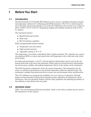
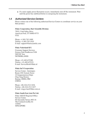
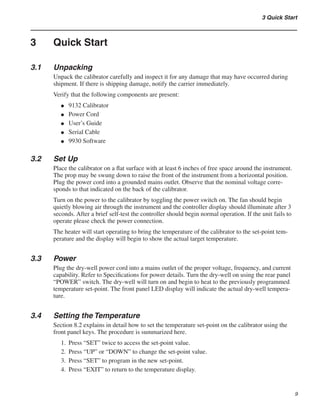
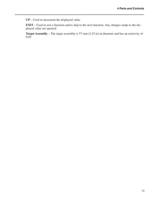
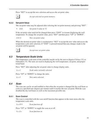
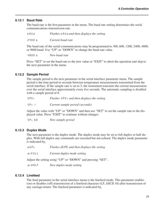
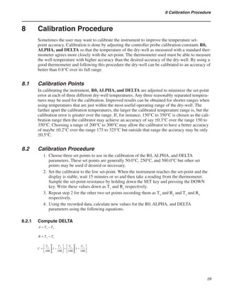
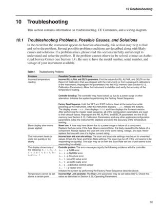
Table 3 Serial Commands
Command Description
Command
Format
Command
Example Returned
Returned
Example
Acceptable
Values
Display Temperature
Read current set-point s[etpoint] s set: 999.9 {C or F} set: 100.00 C
Set current set-point to n s[etpoint]=n s=200.0 Instrument
Range
Read temperature t[emperature] t t: 999.9 {C or F} t: 55.6 C
Read temperature units u[nits] u u: x u: C
Set temperature units: u[nits]=c/f C or F
Set temperature units to Celsius u[nits]=c u=c
Set temperature units to Fahrenheit u[nits]=f u=f
Read scan mode sc[an] sc scan: {ON or OFF} scan:ON
Set scan mode sc[an]=on/off sc=on ON or OFF
Read scan rate sr[ate] sr srat: 99.9 {C or
F}/min
srat:12.4C/min
Set scan rate sr[ate]=n sr=1.1 .1 to 99.9
Secondary Menu
Read proportional band setting pr[opband] pr pb: 999.9 pb: 15.9
Set proportional band to n pr[opband]=n pr=8.83 Depends on
Configuration
Read heater power
(duty cycle)
po[wer] po po: 999.9 po: 1.0
Configuration Menu
Operating Parameters Menu
Read high limit hl hl hl:999 hl:126
Set high limit hl=n hl=90 0–126
Serial Interface Menu
Read serial sample setting sa[mple] sa sa: 9 sa: 1
Set serial sampling setting to n
seconds
sa[mple]=n sa=0 0 to 999
Set serial duplex mode: du[plex]=f[ull]/
h[alf]
FULL or HALF
Set serial duplex mode to full du[plex]=f[ull] du=f
Set serial duplex mode to half du[plex]=h[alf] du=h
Set serial linefeed mode: lf[eed]=on/of[f] ON or OFF
Set serial linefeed mode to on lf[eed]=on lf=on
Set serial linefeed mode to off lf[eed]=of[f] lf=of
Calibration Menu
Read R0 calibration parameter r[0] r r0: 999.999 r0: 100.578
Set R0 calibration parameter to n r[0]=n r=100.324 90 to 110
Read ALPHA calibration parameter al[pha] al al: 9.9999999 al: 0.0038573
Set ALPHA calibration parameter to n al[pha]=n al=0.0038433 .002 to .005
Read DELTA calibration parameter de[lta] de de:9.99999 de: 1.507
35. 29
8 Calibration Procedure
Sometimes the user may want to calibrate the instrument to improve the temperature set-
point accuracy. Calibration is done by adjusting the controller probe calibration constants R0,
ALPHA, and DELTA so that the temperature of the dry-well as measured with a standard ther-
mometer agrees more closely with the set-point. The thermometer used must be able to measure
the well temperature with higher accuracy than the desired accuracy of the dry-well. By using a
good thermometer and following this procedure the dry-well can be calibrated to an accuracy of
better than 0.8°C over its full range.
8.1 Calibration Points
In calibrating the instrument, R0, ALPHA, and DELTA are adjusted to minimize the set-point
error at each of three different dry-well temperatures. Any three reasonably separated tempera-
tures may be used for the calibration. Improved results can be obtained for shorter ranges when
using temperatures that are just within the most useful operating range of the dry-well. The
farther apart the calibration temperatures, the larger the calibrated temperature range is, but the
calibration error is greater over the range. If, for instance, 150°C to 350°C is chosen as the cali-
bration range then the calibrator may achieve an accuracy of say ±0.3°C over the range 150 to
350°C. Choosing a range of 200°C to 300°C may allow the calibrator to have a better accuracy
of maybe ±0.2°C over the range 175 to 325°C but outside that range the accuracy may be only
±0.5°C.
8.2 Calibration Procedure
Choose three set points to use in the calibration of the R0, ALPHA, and DELTA
parameters. These set points are generally 50.0°C, 250°C, and 500.0°C but other set
points may be used if desired or necessary.
Set the calibrator to the low set-point. When the instrument reaches the set-point and the
display is stable, wait 15 minutes or so and then take a reading from the thermometer.
Sample the set-point resistance by holding down the SET key and pressing the DOWN
key. Write these values down as T1
and R1
respectively.
Repeat step 2 for the other two set points recording them as T2
and R2
and T3
and R3
respectively.
Using the recorded data, calculate new values for the R0, ALPHA, and DELTA
parameters using the following equations.
8.2.1 Compute DELTA
1.
2.
3.
4.
36. 9132 Portable IR Calibrator
User’s Guide
30
T1-3
- Measured temperature using a thermometer
R1-3
– Value of the set-point resistance from the display. (Press SET and DOWN at the same
time.)
Where:
T1
and R1
are the measured temperature and resistance at 50.0°C
T2
and R2
are the measured temperature and resistance at 200.0°C
T3
and R3
are the measured temperature and resistance at 350.0°C
8.2.2 Compute R0 and ALPHA
Where:
delta is the new value of DELTA computed above
Program the new values for DELTA (delta), R0 (rzero) ALPHA (alpha) into the instrument
using the following steps.
Press the SET and EXIT keys at the same time and then press SET until R0 is displayed.
Press SET then use the UP or DOWN keys until the correct numerical setting is
displayed. Press SET to accept the new value.
Repeat step 2 for ALPHA and DELTA.
1.
2.
3.
37. 31
8 Calibration Procedure
8.2.3 Accuracy and Repeatability
Check the accuracy of the instrument at various points over the calibration range. If instrument
does not pass specification at all set-points, repeat the Calibration Procedure.
38.
39. 33
9 Maintenance
9 Maintenance
The calibration instrument has been designed with the utmost care. Ease of operation
and simplicity of maintenance have been a central theme in the product development.
Therefore, with proper care the instrument should require very little maintenance. Avoid
operating the instrument in dirty or dusty environments.
If the outside of the instrument becomes soiled, it may be wiped clean with a damp cloth
and mild detergent. Do not use harsh chemicals on the surface, which may damage the
paint.
The calibrator should be handled with care. Avoid knocking or dropping the calibrator.
If the mains supply cord becomes damaged, replace it with a cord with the appropriate
gauge wire for the current of the instrument. If there are any questions, call an
Authorized Hart Scientific Service Center (see Section ) for more information.
Before using any cleaning or decontamination method except those recommended by
Hart, users should check with an Authorized Hart Scientific Service Center (see Section )
to be sure that the proposed method will not damage the equipment.
If the instrument is used in a manner not in accordance with the equipment design, the
operation of the instrument may be impaired or safety hazards may arise.
●
●
●
●
●
●
40.
41. 35
10 Troubleshooting
10 Troubleshooting
This section contains information on troubleshooting, CE Comments, and a wiring diagram.
10.1 Troubleshooting Problems, Possible Causes, and Solutions
In the event that the instrument appears to function abnormally, this section may help to find
and solve the problem. Several possible problem conditions are described along with likely
causes and solutions. If a problem arises, please read this section carefully and attempt to
understand and solve the problem. If the problem cannot otherwise be solved, contact an Autho-
rized Service Center (see Section 1.4). Be sure to have the model number, serial number, and
voltage of your instrument available.
Table 4 Troubleshooting Problems
Problem Possible Causes and Solutions
Incorrect temperature
reading
Incorrect R0, ALPHA, and DELTA parameters. Find the values for R0, ALPHA, and DELTA on the
Report of Calibration that was shipped with the instrument (or from subsequent calibrations
of the instrument). Reprogram the parameters into the 9132 memory (see Section 6.13,
Calibration Parameters). Allow the instrument to stabilize and verify the accuracy of the
temperature reading.
Controller locked up. The controller may have locked up due to a power surge or other
aberration. Initialize the system by performing the Factory Reset Sequence.
Factory Reset Sequence. Hold the SET and EXIT buttons down at the same time while
powering up the instrument. After the instrument displays -init-, release the buttons.
The display shows -init-, then displays 9132, and then displays the firmware version.
After performing the master reset sequence, all of the configuration parameters are reset
to their default values. Reprogram the R0, ALPHA, and DELTA parameters into the 9132
memory (see Section 6.13, Calibration Parameters) and any other applicable configuration
parameters. Allow the instrument to stabilize and verify the accuracy of the temperature
reading.
Blank display after mains
power applied
Blown fuse. A fuse may have blown due to a power surge or failure of a component.
Replace the fuse once. If the fuse blows a second time, it is likely caused by the failure of a
component. Always replace the fuse with one of the same rating, voltage, and type. Never
replace the fuse with one of a higher current rating.
The Instrument heats or
cools too quickly or too
slowly
Incorrect scan and scan rate settings. The scan and scan rate settings may be set to unwanted
values. Check the Scan and Scan Rate settings. The scan may be off (if the unit seems to be
responding too quickly). The scan may be on with the Scan Rate set low (if unit seems to be
responding too slowly).
The display shows any of
the following: err 1, err 2,
err 3, err 4, Err 5, Err
6, or Err 7
Controller problem. The error messages signify the following problems with the controller.
Err 1 - a RAM error
Err 2 - a NVRAM error
Err 3 - a Structure error
Err 4 - an ADC setup error
Err 5 - an ADC ready error
Err 6 – a defective control sensor
Err 7 – a heater error
Initialize the system by performing the Factory Reset Sequence describe above.
Temperature cannot be set
above a certain point
Incorrect High Limit parameter. The High Limit parameter may be set below 500°C. Check this
value as described in Section 6.11, Operating Parameters.
42. 10.2 Comments
11.2.1
10.2.1 EMC Directive
Hart Scientifics’ equipment has been tested to meet the European Electromagnetic Compatibili-
ty Directive (EMC Directive, 89/336/EEC). The Declaration of Conformity for your instrument
lists the specific standards to which the unit was tested.
11.2.2
10.2.2 Low Voltage Directive (Safety)
In order to comply with the European Low Voltage Directive (73/23/EEC), Hart Scientific
equipment has been designed to meet the IEC 1010-1 (EN 61010-1) and the IEC 1010-2-010
(EN 61010-2-010) standards.