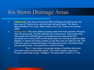
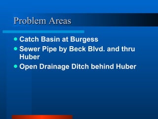
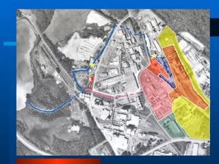
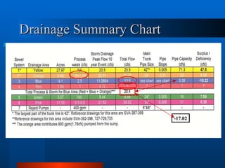
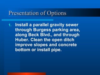
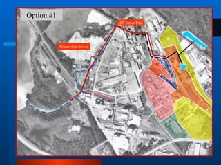
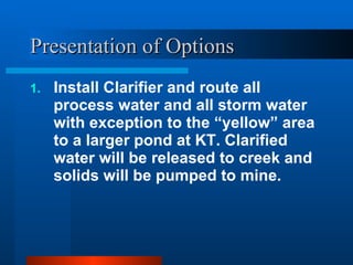
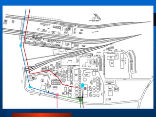
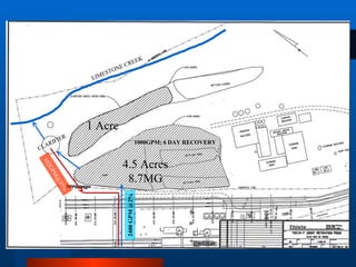
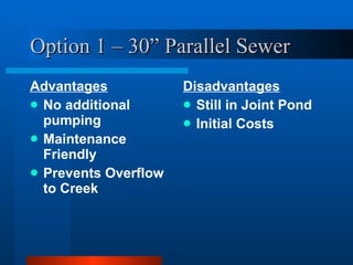
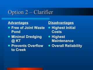
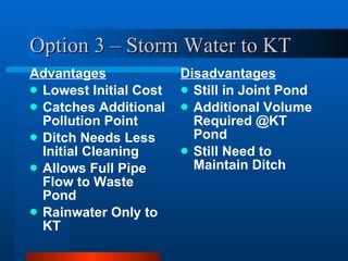
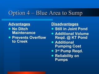
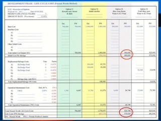
Project Overview Sandersville Plant Drainage Thiele Kaolin Company
Outline of Presentation Present Existing Drainage Basins & Systems Define Existing Problems w/ Systems 4 Possible Solutions to System Problems
Existing Drainage Basins & Systems Six Storm Drainage Basins Seven Systems for Transporting Waste.
Six Storm Drainage Areas Yellow Area.   This area contains the office buildings and parking lots, the lawn east of Thiele’s drive, and the lower rail road tracks. The area is approximately 27.97 acres. Storm water is 23.5 cfs. There is no process water. Orange Area.   This area collects process water from both calciners, #4 spray drier, #5 spray drier, and the calcined slurry make-down. The process flow rate ranges from 400-600 gpm on average and can peak when both scrubbers are running at #4 and #5 spray driers are running at approximately 800gpm. If railcars are being washed out the flow rate can spike as well. The 9.84 acre area is comprised largely of building structures, concreted tracks and graveled tracks. The peak storm runoff is 22.5cfs.  Blue Area.   The 4.1 acre area is comprised largely of building structures, concreted tracks and graveled tracks. This area is largely impervious. Process water flows at app. 1200gpm. The peak storm runoff is 11.1cfs.
Six Storm Drainage Areas Red Area.   The 1.9 acre area is comprised largely of concreted tracks. This area belongs to Burgess but the drainage contributes to the gravity sewer in the blue area. The Peak storm runoff is 4.77 cfs. There is no process water from this area. Green Area.   The 5.07 acre area is comprised of the R&D building and lawn. The peak storm runoff is 8.44 cfs. There is no process water from this area. Pink Area.   The 11.5 acre area is comprised largely of industrial structures, concrete, gravel and low permeability soils. This area is largely impervious. The process water averages at 5.5 cfs.
27.97 Acres Q=23.5 cfs Storm Water 9.84 Acres Q=22.51 cfs Storm Water 800 gpm Process Water 5.07 Acres 8.44 cfs Storm Water 11.55 Acres 21.62 cfs Storm Water 5.5 cfs Process Water 1.89 Acres 4.72 cfs Storm Water 4.1 Acres 11.0864 cfs Storm Water 2.5 cfs Process Water
Seven Systems System #1 .  The gravity system for the yellow drainage area which flows directly to Limestone creek behind Burgess. System #2 .  The pressurized system which is located in the Orange area and pumps to the gravity sewer beginning at Burgess. A retention pond located on KT’s property is part of this system. System #3 .  This system is located in the blue area and is a gravity system which flows thru Burgess and Huber then thru an open ditch to the waste pond. This system has several bottlenecks. Both the blue and red drainage areas contribute to this area. System #4 .  This is the drainage area on Burgess’s property (Red). This transports water to the blue gravity system. System #5 . The storm drainage for the R&D area (green area). System #6 .  The process and storm drainage for the main plant (pink area).  System #7 .The pressurized system that returns waste to the Avant and Hall Mines via two Hazleton 4J pumps.
SYSTEM #3 SYSTEM #1 SYSTEM #2 SYSTEM #4 SYSTEM #5 SYSTEM #6 SYSTEM #7
Reject Pump to Avant Mine
Reject to Hall Mine
Problem Areas Catch Basin at Burgess Sewer Pipe by Beck Blvd. and thru Huber Open Drainage Ditch behind Huber
 
Drainage Summary Chart -17.02
Possible Solutions  Presentation of Options Pros and Cons of Options Economic Analysis of Options Miscellaneous
Presentation of Options Install a parallel gravity sewer through Burgess parking area, along Beck Blvd., and through Huber. Clean the open ditch improve slopes and concrete bottom or install pipe.
Option #1 30” Sewer Pipe Stream-Line Sewer
Ditch Behind Huber
Presentation of Options Install Clarifier and route all process water and all storm water with exception to the “yellow” area to a larger pond at KT. Clarified water will be released to creek and solids will be pumped to mine.
 
4.5 Acres 8.7MG 1 Acre LIMESTONE CREEK CLARIFIER 1000GPM; 6 DAY RECOVERY 2400 GPM @2% 102GPM@35%
Presentation of Options Install a high level overflow at the upper gravity catch basin in Burgess’ parking lot. Reroute  any storm water which exceeds the 18” pipe capacity to the lower existing KT pond. The lower KT pond will need to be dredged to accommodate additional storm water.
 
Presentation of Options Send all of the “blue” area process and storm water to the sump pumps located in the orange area. Pump the total flow across the plant to the upper 42” sewer.
 
Pros and Cons of Options
Option 1 – 30” Parallel Sewer Advantages No additional pumping Maintenance Friendly Prevents Overflow to Creek Disadvantages Still in Joint Pond Initial Costs
Option 2 – Clarifier Advantages Free of Joint Waste Pond Minimal Dredging @ KT Prevents Overflow to Creek Disadvantages Highest Initial Costs Highest Maintenance Overall Reliability
Option 3 – Storm Water to KT Advantages Lowest Initial Cost Catches Additional Pollution Point Ditch Needs Less Initial Cleaning Allows Full Pipe Flow to Waste Pond Rainwater Only to KT Disadvantages Still in Joint Pond Additional Volume Required @KT Pond Still Need to Maintain Ditch
Option 4 – Blue Area to Sump Advantages No Ditch Maintenance Prevents Overflow to Creek Disadvantages Still in Joint Pond Additional Volume Reqd. @ KT Pond Additional Pumping Cost 3 rd  Pump Reqd. Reliability on Pumps
 
Miscellaneous Line to Mines for Dredge 16” ID allows 3500gpm Pump Solids Directly to Mine Est. Cost at $3,000,000

Drainage presentation

  • 1.
    Project Overview SandersvillePlant Drainage Thiele Kaolin Company
  • 2.
    Outline of PresentationPresent Existing Drainage Basins & Systems Define Existing Problems w/ Systems 4 Possible Solutions to System Problems
  • 3.
    Existing Drainage Basins& Systems Six Storm Drainage Basins Seven Systems for Transporting Waste.
  • 4.
    Six Storm DrainageAreas Yellow Area. This area contains the office buildings and parking lots, the lawn east of Thiele’s drive, and the lower rail road tracks. The area is approximately 27.97 acres. Storm water is 23.5 cfs. There is no process water. Orange Area. This area collects process water from both calciners, #4 spray drier, #5 spray drier, and the calcined slurry make-down. The process flow rate ranges from 400-600 gpm on average and can peak when both scrubbers are running at #4 and #5 spray driers are running at approximately 800gpm. If railcars are being washed out the flow rate can spike as well. The 9.84 acre area is comprised largely of building structures, concreted tracks and graveled tracks. The peak storm runoff is 22.5cfs. Blue Area. The 4.1 acre area is comprised largely of building structures, concreted tracks and graveled tracks. This area is largely impervious. Process water flows at app. 1200gpm. The peak storm runoff is 11.1cfs.
  • 5.
    Six Storm DrainageAreas Red Area. The 1.9 acre area is comprised largely of concreted tracks. This area belongs to Burgess but the drainage contributes to the gravity sewer in the blue area. The Peak storm runoff is 4.77 cfs. There is no process water from this area. Green Area. The 5.07 acre area is comprised of the R&D building and lawn. The peak storm runoff is 8.44 cfs. There is no process water from this area. Pink Area. The 11.5 acre area is comprised largely of industrial structures, concrete, gravel and low permeability soils. This area is largely impervious. The process water averages at 5.5 cfs.
  • 6.
    27.97 Acres Q=23.5cfs Storm Water 9.84 Acres Q=22.51 cfs Storm Water 800 gpm Process Water 5.07 Acres 8.44 cfs Storm Water 11.55 Acres 21.62 cfs Storm Water 5.5 cfs Process Water 1.89 Acres 4.72 cfs Storm Water 4.1 Acres 11.0864 cfs Storm Water 2.5 cfs Process Water
  • 7.
    Seven Systems System#1 . The gravity system for the yellow drainage area which flows directly to Limestone creek behind Burgess. System #2 . The pressurized system which is located in the Orange area and pumps to the gravity sewer beginning at Burgess. A retention pond located on KT’s property is part of this system. System #3 . This system is located in the blue area and is a gravity system which flows thru Burgess and Huber then thru an open ditch to the waste pond. This system has several bottlenecks. Both the blue and red drainage areas contribute to this area. System #4 . This is the drainage area on Burgess’s property (Red). This transports water to the blue gravity system. System #5 . The storm drainage for the R&D area (green area). System #6 . The process and storm drainage for the main plant (pink area). System #7 .The pressurized system that returns waste to the Avant and Hall Mines via two Hazleton 4J pumps.
  • 8.
    SYSTEM #3 SYSTEM#1 SYSTEM #2 SYSTEM #4 SYSTEM #5 SYSTEM #6 SYSTEM #7
  • 9.
    Reject Pump toAvant Mine
  • 10.
  • 11.
    Problem Areas CatchBasin at Burgess Sewer Pipe by Beck Blvd. and thru Huber Open Drainage Ditch behind Huber
  • 12.
  • 13.
  • 14.
    Possible Solutions Presentation of Options Pros and Cons of Options Economic Analysis of Options Miscellaneous
  • 15.
    Presentation of OptionsInstall a parallel gravity sewer through Burgess parking area, along Beck Blvd., and through Huber. Clean the open ditch improve slopes and concrete bottom or install pipe.
  • 16.
    Option #1 30”Sewer Pipe Stream-Line Sewer
  • 17.
  • 18.
    Presentation of OptionsInstall Clarifier and route all process water and all storm water with exception to the “yellow” area to a larger pond at KT. Clarified water will be released to creek and solids will be pumped to mine.
  • 19.
  • 20.
    4.5 Acres 8.7MG1 Acre LIMESTONE CREEK CLARIFIER 1000GPM; 6 DAY RECOVERY 2400 GPM @2% 102GPM@35%
  • 21.
    Presentation of OptionsInstall a high level overflow at the upper gravity catch basin in Burgess’ parking lot. Reroute any storm water which exceeds the 18” pipe capacity to the lower existing KT pond. The lower KT pond will need to be dredged to accommodate additional storm water.
  • 22.
  • 23.
    Presentation of OptionsSend all of the “blue” area process and storm water to the sump pumps located in the orange area. Pump the total flow across the plant to the upper 42” sewer.
  • 24.
  • 25.
    Pros and Consof Options
  • 26.
    Option 1 –30” Parallel Sewer Advantages No additional pumping Maintenance Friendly Prevents Overflow to Creek Disadvantages Still in Joint Pond Initial Costs
  • 27.
    Option 2 –Clarifier Advantages Free of Joint Waste Pond Minimal Dredging @ KT Prevents Overflow to Creek Disadvantages Highest Initial Costs Highest Maintenance Overall Reliability
  • 28.
    Option 3 –Storm Water to KT Advantages Lowest Initial Cost Catches Additional Pollution Point Ditch Needs Less Initial Cleaning Allows Full Pipe Flow to Waste Pond Rainwater Only to KT Disadvantages Still in Joint Pond Additional Volume Required @KT Pond Still Need to Maintain Ditch
  • 29.
    Option 4 –Blue Area to Sump Advantages No Ditch Maintenance Prevents Overflow to Creek Disadvantages Still in Joint Pond Additional Volume Reqd. @ KT Pond Additional Pumping Cost 3 rd Pump Reqd. Reliability on Pumps
  • 30.
  • 31.
    Miscellaneous Line toMines for Dredge 16” ID allows 3500gpm Pump Solids Directly to Mine Est. Cost at $3,000,000