Downloaded 14 times
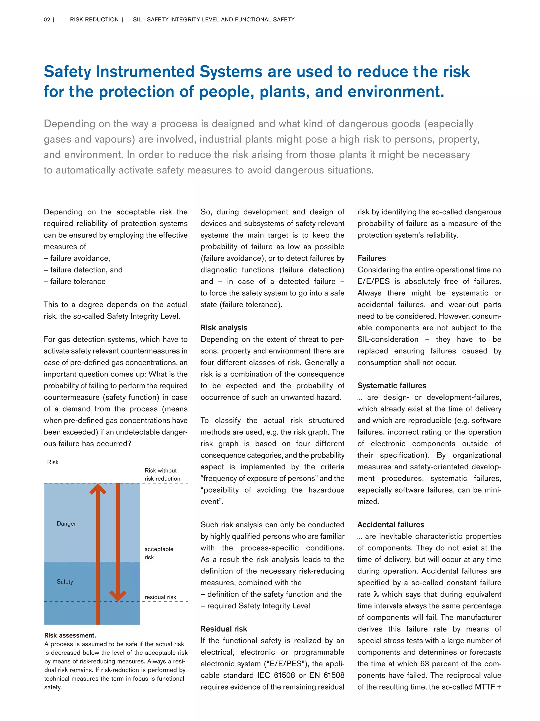
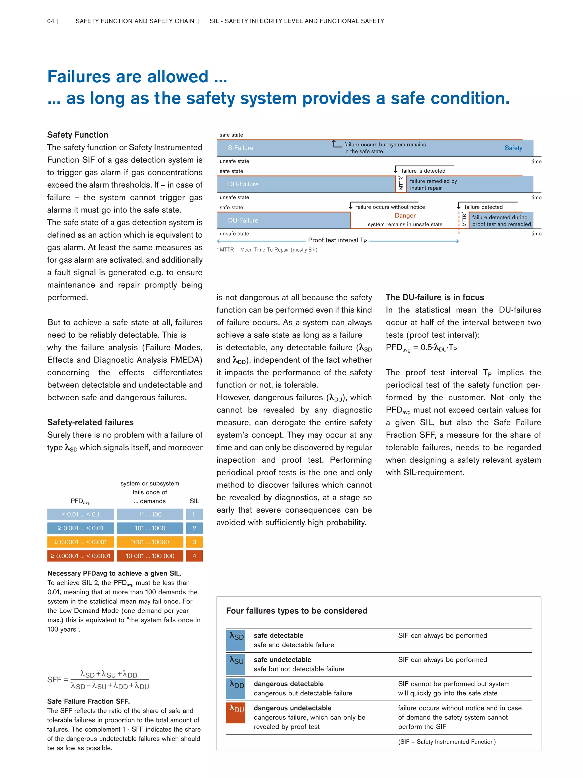

A process is assumed to be safe if the actual risk is decreased below the level of acceptable risk through risk-reducing measures. Safety instrumented systems use functional safety to automatically activate safety measures and avoid dangerous situations. The required reliability of protection systems depends on the safety integrity level (SIL), which is determined through risk analysis of potential consequences, exposure to hazards, and avoiding hazardous events. Gas detection systems must activate safety countermeasures if gas concentrations exceed defined levels. Their safety function is to trigger gas alarms, and upon failure must go to a safe state of equivalent alarm activation. The probability of failure for safety functions is evaluated to ensure protection systems meet the necessary SIL level through factors like proof testing and detectable versus undetectable