Download to read offline
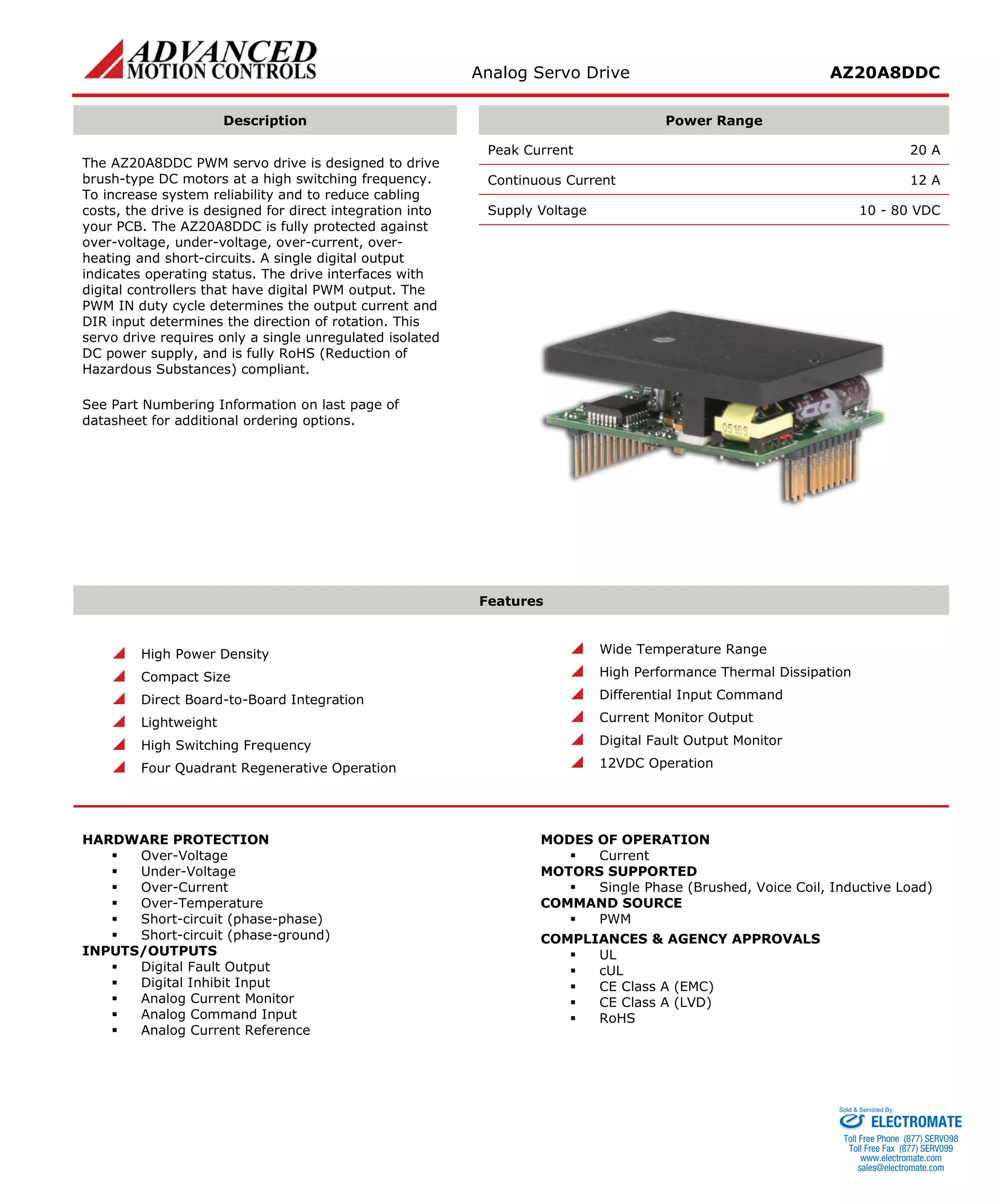
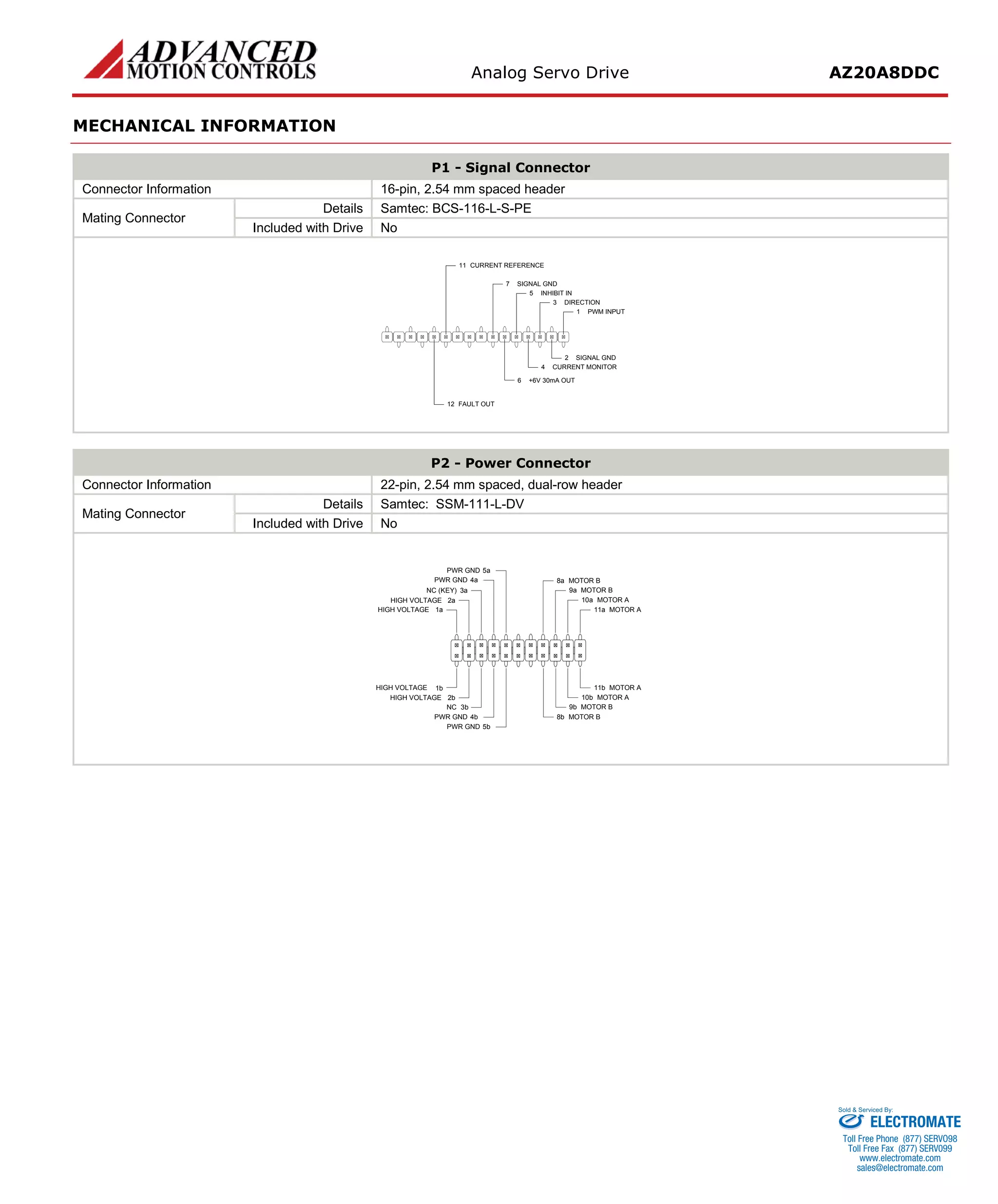

The AZ20A8DDC is a PWM servo drive designed to drive DC motors from 10-80VDC. It can provide up to 20A of peak current and 12A of continuous current. The drive is fully protected against overloads and faults, and integrates directly onto PCBs for compact designs. It requires only a single power supply and PWM command input to control motor direction and current.


![Vibe Coding vs. Spec-Driven Development [Free Meetup]](https://cdn.slidesharecdn.com/ss_thumbnails/vibecodingvsspecdrivendevelopment-251209105622-43f455e7-thumbnail.jpg?width=640&height=640&fit=bounds)


