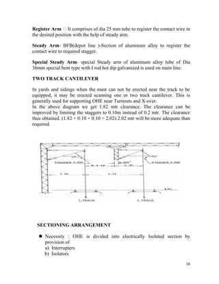
SlideShare a Scribd company logo
1 of 36
TRAINING REPORT
ON
“TRACTION SYSTEM IN DMRC“
DELHI METRO RAIL CORPORATION LTD.
SUBMITTED BY
VIKANKSH NATH
Roll
No.-13BEE-0066
B.Tech 3rd year 2016
Mentor's Name:- Mr. LOKENDRA SINGH
(Training Coordinator Electrical)
1
CERTIFICATE
This is To cerTify ThaT Mr. ViKaNKsh
NaTh(roll No. 13Bee-0066) is a sTUDeNT of B.Tech
elecTrical eNGG. of JaMia Millia islaMia,VocaTioNal
TraiNee has coMpleTeD his sUMMer TraiNiNG UNDer The
GUiDaNce of Mr. loKeNDra siNGh sir froM 06.06.2016 To
08.07.2016 iN DMrc liNe-6 (sariTa Vihar) oN “TracTioN
sysTeM “ sUccessfUlly.
-Mr. LOKENDRA SINGH
(Training Coordinator
Electrical)
___________________
SIGNATURE
_
2
ACKNOWLEDGEMENT
It is indeed a great pleasure for me to get a chance to get an insight into
working of a massive and a prestigious organization like DELHI METRO
RAIL COORPORATION.
I am grateful to for providing me this opportunity.
I express my sincere thanks and regards to MR. LOKENDRA SINGH SIR
for his guidance and support throughout.
Thanks to all technicians, staff and workers of DMRC for their whole
hearted corporation extended to me, without which it would not have been
possible to get all the practical knowledge of work at such a prestigious
organization.
3
Thank you
INDEX
S.NO CONTENT PAGE NO.
1 DMRC COMPANY PROFILE 05-07
2 INTRODUCTION 08
3 Organizational structure of power distribution
system
09
4 ELECTRIC TRACTION SYSTEM 10
5 OVERHEAD EQUIPMENT (OHE) 11-19
6 POWER SUPPLY INSTALLATION (PSI) 20-27
7 SCADA 28-34
8 CONCLUSION 34
4
DMRC
(Delhi Metro Rail Corporation)
COMPANY PROFILE
The following section contains the details of DMRC as an organization.
Why it was created and how it has been maintained.
THE NEED?
Delhi, the national capital with the population of about 12 million is,
perhaps, the only city of its size in the world, which depends almost entirely
on buses on it sole mode of mass transport. Bus services are inadequate and
heavily over-crowded. This situation had led to proliferation of personalized
5
vehicles, so much so that Delhi has more registered vehicle than the total
number of vehicles in Mumbai, Calcutta and Chennai put together. Nearly
70% of these are two wheelers. The result of extreme congestion on the road,
ever slowing speeds, increasing accident rate, fuel wastage and environmental
pollution. Delhi has now become the fourth most cities in the world, with
automobiles contributing more than two thirds of the total atmospheric
pollution. Pollution related health problems are reaching disconcerting levels.
To meet forecast transport demand for the year 2001, the number of
buses will have to be at least doubled and personalized vehicles will grow
three fold. This sure to lead to further worsening of the levels of congesting
and pollution, which had already crossed acceptable limits in many part of the
city.
Immediate steps are, therefore, needed to improve both the quality and
availability of mass transport service. This is possible only if a rail-based mass
transit system, which is non-polluting, is introduced in the city without further
delay.
DELHI METRO PROJECT
The Delhi Metro is a rapid transit system serving Delhi, Gurgaon and
Noida in the National Capital Region of India. The network consists of six
lines with a total length of 190 kilometers. The metro has 142 stations of
which 35 are underground. It has a combination of elevated, at-grade and
underground lines and uses both broad gauge and standard gauge rolling
stock.
Delhi Metro is being built and operated by the Delhi Metro Rail
Corporation Limited (DMRC). As of April 2010, DMRC operates more than
100 trains daily between 6:00 — 23:00 with a frequency of 3 to 4.5 minutes.
The trains have four to six coaches and the power output is supplied by 25-
kilo volt, 50 Hz AC through overhead catenary. The metro has an average
daily ridership of over a million commuters and has carried over a billion
commuters in seven years since its inception
Planning for the metro started in 1984, when the Delhi Development
Authority and the Urban Arts Commission came up with a proposal for
6
developing a multi-modal transport system for the city. The Government of
India and the Government of Delhi jointly set up the Delhi Metro Rail
Corporation (DMRC) in 1995. Construction started in 1998, and the first
section, on the Red Line, opened in 2002, followed by the Yellow Line in
2004, the Blue Line in 2005, its branch line in 2009 and the Green Line in
2010. Subsequently, these lines have been extended and new lines are under
construction in Phase II of the project, including the Delhi Airport Metro
Express and the Violet Line which are scheduled to be completed by
September 2010.
ECONOMIC BENEFITS
The Delhi MRTS is essentially a "social" sector project, whose benefits
will pervade wide sections of economy. The modified first phase will generate
substantial benefits to the economy by the way of:
• Time saving for commuters
• Reliable and safe journey
• Reduction in atmospheric pollution
• Reduction in accident
• Reduced fuel consumption
• Reduced vehicle operating costs
• Increase in the average speed of road vehicles
• Improvement in the quality of life
• More attractive city for economic investment and growth
Economic IRR of the project works out to 21.4%, even though the financial
IRR is less than 3%.
7
INTRODUCTION
Delhi, the capital city of India, has a population of about 15 million,
which is expected to reach 20 million by the year 2025. Every day, about 10
million passenger trips are performed in Delhi by motorized modes. In view
of this passenger density, the Delhi Metro Project was sanctioned by the
Government of India in the year 1966. Implementation of Delhi Metro Project
is planned in 4 phases, for a total network of 245 km, most of which (228 km)
is elevated with a small underground section of 27 km.
The Phase I of the Project comprises of three lines (line I/II/III) of 65
km section (14 km underground and 51 km elevated rail corridor). All these
three lines have been commissioned. Line — I is totally elevated and line — II
is underground (11km), where as line-III is partly underground, with the major
portion being elevated. Lines I & III are provided with 25 kV ac. Line-II was
originally designed with 1500 V dc and was subsequently changed to 25 kV
ac. This line was delivered in two distinct phases. The cut-and-cover portion
covering the Vishwa Vidyalya to Kashmere Gate area was open to revenue
operation on 20th December 2004. The remaining section between Kashmere
Gate to Central Secretariat was constructed by a shield-driven Tunnel Boring
Machine and cut & covers method, was put into revenue use on 2nd July
2005. All these 3-lines are further being extended in Phase II of the Project.
Delhi Metro is designed as a heavy metro system to cater to 60,000
PHPDT (Peak Hour Passenger per Direction Trip), up gradable to 80,000
PHPDT. The Detailed Study indicated that while all 3 Traction System (750
V dc. 1500 V dc & 25 kV ac) are technically feasible, but 1500 v dc or 25 kV
ac is more desirable for such a high level of traffic from the reliability point of
view. Normally, 25 kV ac requires a minimum tunnel dia of 5.8 m. Tunnel
dia of 5.4 m with 1500 v dc was considered from many dimensions viz.
8
Rolling Stock, electrical clearances etc. It was estimated to be economical.
However, from reliability and other considerations of benefits of commonality
of traction & Rolling Stock, 25 kV ac traction systems is well suited for the
expansion of the system from 60,000 to 80,000 PHPDT as the elevated
sections are provided with 25 kV ac traction.
Organizational structure of power distribution
system:
NDPL or BSES provides a supply of 132 kV or 66 kV to the Receiving
Sub Station (RSS). From this, it is step down into 25 kV and 33kV by using
traction transformers and auxiliary transformers respectively. 33 kV supply is
given to the ASS and 25 kV to FP (Feeding Post). ASS supplies power to
auxiliary equipments like Escalators, lifts, cooling towers, etc. FP supplies this
25 kV power to OHE (Over Head Equipments) and other traction
equipments.220KV,132KV or 66kV supply is received from DISCOMS at
RSS.This supply is stepped down to 33kV for auxiliary supply at stations.
Two cables run along the via-duct and at each station to form ring main
system.
In ASSs, the supply is further stepped down to 415V and fed to MDB
RSS
(BSES/NDPL)
AMS
ASS FP
AUXILIARY
EQUIPMENT
OHE & other
TRACTION equipments
9
(Main distribution board) of ESR.
ELECTRIC TRACTION SYSTEM
Electric traction is an environmental friendly, pollution-free and energy
efficient mode of transport and offers an excellent alternative to fossil fuels as
a source of energy. Electric traction reduced nation’s dependence on largely
imported diesel oil as it is capable of using indigenously available alternative
sources of primary energies, like coal of any grade, hydro power, surplus
petroleum gas, nuclear power etc. In view of the hike in oil prices, it is a
challenge to contain cost and make judicious use of energy in hauling trains
The electric traction system is the system by which traction motor is moved
with loads. Now a day’s ac 25kv 50hz.1-ph system is universally adopted
for traction movement. Power comes from OHE equipment via pantograph
dj(circuit breaker) to the transformer then to the rectifier where it is
converted to dc to feed the traction motor finally the track provides the
return path of the current. Thus traction system works.
Electric traction system used in DMRC has three parts:
 PSI
It deals with the High Voltage Equipments for distribution of
energy to meet Auxiliary & Traction requirement.
 OHE
It deals with the Over Head Equipments located overhead above the
track to supply power for train operation.
 SCADA
It controls all high & low voltage equipments remotely from OCC.
10

OVERHEAD EQUIPMENT(OHE)
The overhead equipment above the tracts contain the following:
11
CATENARY WIRE:
It is made of copper cadmium alloy 19 strands of 2.10 mm dia,
representing a total cross section of about 65mm*mm
CONTACT WIRE:
A grooved hard drawn pure copper contact wire,cast anf flattened type of
150mm*mm cross section.
DROPPER:
Contact wire is supported from the catenary wire by means of dropper of
tin bronze cross section of 12 mm*mm ending with eyes shall be crimped
and reinforced automatic clamps on catenary and contact wire.
HEIGHT OF CONTACT WIRE:
The normal height of contact wire for regulated OHE = 5.00 m,5.15m for
unregulated OHE and 5.20m for depots and inspection pits.
STAGGER
The contact wire is staggered so that as the pantograph glides along, the
contact wire sweeps across the current collecting strips of the pantograph
12
up to a distance of 200 mm on either side of the centre line on straight runs
and 240 mm on one side on curves. This ensures a uniform wear of the
current collecting strips of the pantographs.
OVERLAPS
The OHE conductors are terminated at intervals of about1140m with an
overlap generally as shown, the conductor height being so adjusted that the
pantograph glides from one conductor to the other smoothly.
There are two types of overlap spans as under:-
(a) Un insulated overlap spans where the distance of separation between
two contact wires is 200 mm and the two conductors are permanently
connected together electrically by jumpers.
(b)Insulated overlaps, where the two OHE systems are kept apart at a
distance of 500mm. normally the electrical discontinuity at insulated
overlaps is bridged by interrupter or booster transformer or Isolator
Switches.
JUMPER
Jumpers are an arrangement of conductors with multi strand copper wire
used for electrical continuity which provides electrical connection between
two conductors or equipment. In section 26 Sq mm 75 Sq mm and 164 Sq
mm flexible copper wire are used as jumper wire.
MAST
A single vertical post embedded in the foundation or otherwise rigidly
fixed in vertical position to support the overhead equipment with cantilever
assembly. Mast may be rolled section or fabricated. The uprights of portals
and TTCs are also called Mast.
13
(a) TYPES OF MAST
Nine types of Masts are basically used. They are designated as’’
• 150x150 BFB (Broad Flanged Beam) – 6–x6– BFB
• 200x200 BFB- 8––X8––
• 200x150 RSJ (Rolled Steel Joist) - 8–x6– RSJ
• B-100
• B-125
• B-150
• B-175
• B-200
• B-225
• B-250
(b) SELECTION OF MAST
Standard Applications for the Masts are in–
1) Single OHE
2) Anti Creep
3) Overlaps
4) OHE Terminations
(c) ARRANGEMENT OF MAST
If the structures are away form Track centre, they can be placed opposite in
the same chain age.
PORTAL
On multiple track sections, where adequate track centers are not available and
tracks can not be slewed, portals are used. Each portal consists of two
fabricated uprights and one fabricated boom consisting of one central piece
and two end pieces.
CANTILEVER SYSTEM AND ITS PARTS
14
51
51
Cantilever assembly Rail Corridor
It is an insulated swiveling type structural member, comprising of different
sizes of steel tubes, to support and to keep the overhead catenary system in
position so as to facilitate current collection by the pantograph at all speed
without infringing the structural members. It consists of the following
structural members:-
Stay arm ’ It comprises of seamless GI hollow tube dia 38 mm /thickness
4mm size and an adjuster at the end to keep the bracket tube in position. It is
insulated from mast by stay arm insulator.
Bracket tube ’ It comprises of seamless GI hollow tube dia 49mm/4.5mm
thickness or seamless GI hollow tube dia 38 mm (standard) bracket tube and
insulated by bracket insulator. OHE is supported from this member by
catenary suspension bracket and catenary suspension clamp.
15
Register Arm ’ It comprises of dia 25 mm tube to register the contact wire in
the desired position with the help of steady arm.
Steady Arm- BFB(depot line )-Section of aluminum alloy to register the
contact wire to required stagger.
Special Steady Arm- special Steady arm of aluminum alloy tube of Dia
36mm special bent type with I rod hot dip galvanized is used on main line.
TWO TRACK CANTILEVER
In yards and sidings when the mast can not be erected near the track to be
equipped, it may be erected scanning one or two track cantilever. This is
generally used for supporting OHE near Turnouts and X-over.
In the above diagram we get 1.82 mtr clearance. The clearance can be
improved by limiting the staggers to 0.10m instead of 0.2 mtr. The clearance
thus obtained. (1.82 + 0.10 + 0.10 = 2.02) 2.02 mtr will be more adequate than
required.
SECTIONING ARRANGEMENT
 Necessity : OHE is divided into electrically Isolated section by
provision of
a) Interrupters
b) Isolators
16
 Purpose : Sectioning is provided to permit Isolation of OHE in smaller
sections for maintenance purposes or to Isolate damaged OHE in case
of breakdown/accident and to permit diversion of trains from up line to
down line or vice versa
 At the same time, more sectioning into many smaller sections will lead
to manual inadvertent errors/operational Inconvenience.
 Hence there should be balance keeping the above in mind.
 With 25kv single phase traction power is tapped from the different
phases of the HV grid.
 A neutral section is provided at the midway between two adjacent
traction substations. This electrically isolates from different phases of
supply that mechanically the OHE is made to run through for smooth
passage of pantograph from one section to other section.
17
 A small length of 27 meter Neutral section remains in power off
condition. The Metro Train has to run by its own momentum only.
 Hence the Neutral section areas are far off from signals.
 Mostly on plain area avoiding gradient of tracks.
 Indication Boards are fixed on the OHE masts in advance for the drivers
to know the approach of Neutral section.
 Instead of every time to operate from Substation Control room, OHE is
fed through the FEEDING POST (FP) which is created in between
Substation and OHE with Interrupters, Double Pole Isolators etc.
 Interrupters are high power switches but does not isolate on its own at
faulty condition. Interrupters controlled either manually or remotely.
 This FP is classified as a switching station in a substation for day to day
operation.
MAINTENANCE SCHEDULE OF OHE.
In order to achieve high reliability and ZERO DEFECT OHE, and to
ensure effective checks on the maintenance work a minimum schedule of
inspections to be carried out each month by the officers and Senior
Subordinate.
The POH of OHE should be planned on a programmed basis so that
every part of the installation receives detailed attention, repair and overhaul at
an interval of 4 year.
MAINTENANCE SCHEDULE
The following schedules of maintenance for the OHE are required to be
followed to ensure good current collection as well as safety of installations
and personnel:
18
1. Foot Patrolling
2. Current Collection Tests
1. FOOT PATROLLING
Foot patrolling can only be done during non-traffic hours. The
patrolman will take permission to enter in the section from the station
controller with clear indication whether he will proceed to next station or will
come back after finishing his work.
The maintainers on patrol duty should particularly look for the following:
a.) Chipped or damaged insulators.
b.) Excessive sagging or hogging of contact wire.
c.) Free movement of auto tensioning device and position of counter weight
with reference to upper and lower limits of movement marked on the mast.
d.) Presence of protective screens, cautions and warning boards and anti-
climbing devices.
e.) Bird nests and pieces of stray wire likely to cause short circuits and
branches of trees likely to infringe the OHE.
f.) Defects in return conductor connecting booster transformers and its
connection with OPC. Oil leakage if any from BT.
g.) Any obstructions including tree branches in the way of free movement of
pantograph and trains.
h.) Any other abnormal/unusual situation.
2. CURRENT COLLECTION TEST
This test is carried out periodically to detect points in OHE at which contact
between the contact wires & pantograph is unsatisfactory, which results in
sparking.
19
a.) This test is carried out during night.
b.) Current collection observation are taken by fixing night vision camera in
the rear cab of electric train and record the behavior of the pantograph while
running in night hours only.
c.) An electrical supervisor or maintainer traveling in the cab can observe
sparking taking place through monitor of the camera kept inside the sallon.
d.) The sparking locations are noted down.
e.) These locations to be attended as soon as possible and eliminate the cause
of sparking.
POWER SUPPLY INSTALLATION (PSI)
Power supply received at High Voltage (220KV/66KV) transformed into 25
KV, for traction feed and 33 KV for the Auxiliary feed by means of power
transformers. Then 25 KV power supply distributed through adequate
20
protecting and sectioning arrangements to Over head centenary system which
feeds the Electrical Multiple Units.
Duplicate 33kV three core cable feeders are laid down along the rail route to
feed power to the auxiliary substations at Rail Corridor stations enroot.
DISTRIBUTION OF POWER SUPPLY
220KV, 132KV or 66kV supply is received from DISCOMS at RSS
Receiving Substation).RSS has two transformers TRACTION
TRANSFORMER (25 KV, 2 INCOMER) and AUXILLARY
TRANSFORMER (33KV, 3 INCOMER which is steeped down to 415 V)
This supply is stepped down to 33kV for auxiliary supply at stations.
Two cables run along the via-duct and at each station to form ring main
system. In ASSs, the supply is further stepped down to 415V and fed to MDB
(Main Distribution Board) of ESR.
RSS (RECEIVING SUBSTATION)
Main Equipments of RSS
a. Circuit Breaker
b. Instrument Transformer (CT/CVT)
c. Surge Arrester
d. Isolator
e. Associated Earth Switches
f. Bus Support Insulators
g. Transformers (B.T/T.T)
h. Control & Protection system
i. Power Line Carrier Communication system
j. Relays (Induction Type)
RSS
21
TRACTION (2 NCOMER) AND AUXILLARY (3 INCOMERS)
TRANSFORMER
22
POWER TRANSFORMER i.e. AUXILLARY TRANSFORMER (3
INCOMER)
BATTERY BANK
23
A Single Line Diagram of RSS (Receiving Sub Station)
The power supply arrangement is divided into two broad parts:-
24
1. TSS (Traction Substation)
2. AMS (Auxiliary Main Substation)
1. TSS (Traction substation)
Traction power supply to cater the Overhead electrification for train
movement. Here Traction transformer is used for convert incoming 220,
132 and 66 kv to 25 kv for traction purpose.
2.AMS (Auxiliary main Substation)
25
Auxiliary power supply to cater the electricity requirements of the metro
station. Here auxiliary transformer is used for convert incoming 220, 132
and 66 kv to 33 kv for traction purpose.
It have four switching point in main line
Feeding Post (FP) – It is a supply post where the incoming 25 kV feeder
lines from the substation are terminated, and connected to the overhead
equipment through interrupters.
Sectioning and Paralleling Post (SP) – It is a supply control post situated
mid-way between two feeding posts at the neutral section and provided with
bridging and paralleling interrupters.
26
Sub-sectioning and paralleling post (SSP) – It is a supply control post
where a sectioning and paralleling interrupter is provided.
DOWN LINE
UP LINE
27
Sub-sectioning Post (SS) - (For single line section) it is a supply control post
where a sectioning interrupter is provided.
DOWN LINE
UP LINE
28
SCADA
This section contains information about SCADA and its related features.
What is SCADA?
SCADA stands for Supervisory Control and Data Acquisition. As the name
indicates, it is not a full control system, but rather focuses on the supervisory
level. As such, it is a purely software package that is positioned on top of
hardware to which it is interfaced, in general via Programmable Logic
Controllers (PLCs), or other commercial hardware modules.
WHY IS SCADA
WIDELY ACCEPTED?
The major attraction of SCADA to a municipality is the ability to significantly
reduce operating labor costs, while at the same time actually improve plant or
regional system performance and reliability. Information gathering within a
plant no longer requires personnel to spend time wandering all over the site,
and correspondingly the frequency of field site inspections required in a
regional system can be minimized
SCADA (SUPERVISORY CONTROL AND DATA ACQUISITION
SYSTEM)
Supervision:
 SCADA lets the operator supervise the process interactively with
schematic pictures which illustrate the real process and direct the
operator to make correct decisions.
Control:
 The operator performs control operations-open, close, lower,
higher, etc- by activating function keys, dialogs and windows.
29
Data acquisition:
 Process information is stored on a process database and a report
database. The real-time process database stores incoming and
outgoing process data signals. Process communication from and
to the base system passes through the process database.
 The report database stores historical data and mathematically or
statistically handled values. It also executes SCIL programs
based on time or events.
Substation Automation system
Substation Automation means that the substation has equipment, which
enables communication with the primary equipment and use of process data
for supervision, control and communication.
The functions may include:
 viewing status of breakers and disconnectors
 controlling the breakers and disconnectors
 dynamic coloring of the busbars
 viewing and setting of protection parameters
 viewing condition of auxiliary equipment e.g. batteries
 collection of metering data
 Transferring data to network control center (S).
In addition, a substation automation application may include user
authorization, event handling and alarm handling.
Application Areas
SCADA is system for local and remote control applications suitable for
electrical and non-electrical distribution areas.
The SCADA-based electrical application areas are:
• Power transmission and distribution
30
The SCADA-based non- electrical application areas are:
 Water purification and distribution
 Waste water treatment,Oil and gas distribution etc.
The SCADA System performs 03 main tasks:The SCADA System performs 03 main tasks:
•• Remote Monitoring (RM).Remote Monitoring (RM).
The status of various equipment such as circuit breaker, isolator etc. of allThe status of various equipment such as circuit breaker, isolator etc. of all
sub-stations can be monitored will be shown to the operator in the mimicsub-stations can be monitored will be shown to the operator in the mimic
diagram of the Operator station.diagram of the Operator station.
•• Remote Control (RC).Remote Control (RC).
TPC can open or close the CB, Interrupters, isolators and tap changers ThisTPC can open or close the CB, Interrupters, isolators and tap changers This
function is needed while giving power block, supply change-over or isolationfunction is needed while giving power block, supply change-over or isolation
of faulty equipment and sections and may return them back to service on theof faulty equipment and sections and may return them back to service on the
establishment of normalcy.establishment of normalcy.
•• Tele MeasuringTele Measuring
Various analog measurements like voltage, Current, Energy consumption, DVarious analog measurements like voltage, Current, Energy consumption, D
etc. can be monitored by the SCADA software.etc. can be monitored by the SCADA software.
Hardware
As discussed above the Hardware unit consists of the RTUs and the
communication links.
REMOTE TERMINAL UNITREMOTE TERMINAL UNIT
1. DIGITAL INPUT CARD (For Monitoring of status)
2. DIGITAL OUT-PUT CARD (For Command execution)
3. ANALOG INPUT CARD (For Measurement of analog values)
4. CPU CARD
5. POWER SUPPLY CARD
31
DIGITAL INPUT CARDDIGITAL INPUT CARD
•• This card is used to collect the status of the sub-stationThis card is used to collect the status of the sub-station
equipments e.g. close/open status, SF6 gas status,equipments e.g. close/open status, SF6 gas status,
Local/Remote status, Protection relay status etc.Local/Remote status, Protection relay status etc.
•• The binary input board 23BE21 is used for the isolatedThe binary input board 23BE21 is used for the isolated
input of up to 16 binary process signals.input of up to 16 binary process signals.
•• Scanning and processing of the inputs are executed withScanning and processing of the inputs are executed with
the high time resolution of 1 ms.the high time resolution of 1 ms.
• Works at a supply voltage of 48V DCWorks at a supply voltage of 48V DC
32
DIGITAL INPUT CARD
• Two Types of Indication :
• Single Indication : Single Contact is used
• Double Indication : Double Contact (1NO+1NC is
used)
It is used only for close/open status.
1 0 Close
0 1 Open
0 0 Intermediate
1 1 Faulty
33
DIGITAL OUTPUT MODULE 23BA20DIGITAL OUTPUT MODULE 23BA20
•• This card is used to execute close/open command to the circuitThis card is used to execute close/open command to the circuit
breakers, isolators etc.breakers, isolators etc.
•• Total 16 Nos. Command can be executed from one card.Total 16 Nos. Command can be executed from one card.
•• ST : common malfunction information of the boardST : common malfunction information of the board
PST: command output fault condition display the monitoring system respondsPST: command output fault condition display the monitoring system responds
CO: Command output display during output time.CO: Command output display during output time.
CPU CARD 23ZG21
• Central Control Unit 80486 based working Processor (VAP)
• 8752 based Peripheral Bus Processor (PBP)
• Reading process events from the input boards.
• Writing commands to the output boards.
• Serial communication with central systems
COM A : OCC
COM B : S/BY CONTROL CENTRE
NFK : S/BY CONTROL CENTRE
Tele-commands
• Close/open Command
34
• Tap low/Raise command
• SCADA Permissive command
Concept of SCADA Permissive command: There are two modes of control
locally from the control panel of CB and remotely from OCC i.e. through
SCADA. This command is initiated by the operator on the request of the field
staff to operate the circuit breaker locally. In the absence of SCADA
permissive command, CB cannot be operated locally.
PLC Functionalities in RTU – A Brief Description
The Local Automation Function (LAF) is the powerful tool used in the
SPIDER RTU for the implementation of PLC functionalities. The logics can
be prepared through LAF program so that RTU can take the decisions
independently. The action taken by PLC is faster and reliable
The LAF program is a PLC program and is stored on EE – devices. LAF
programs can be loaded by the PTS utility from a personal computer or a lap
top. The LAF program is read out of the EE-devices at start up and translated
from pseudo-code into runtime code. The LAF runtime program is stored in
RAM devices.
Purpose of a PLC program
• In a master - slave system, PLC which is acting as a slave works as an
independent device
• In case of combinational logic, it is easy to implement in PLC logic
• Action taken by PLC is faster
• It works even the master goes down / communication breaks
35
CONCLUSION
Through this report I got the brief idea about what has been done in the
training to facilitate the evaluation process of TRACTION SYSTEM IN
DMRC. I studied about the traction system in general and it–s various parts
(OHE, PSI and SCADA).
On the whole this report gives the clear picture of my experience in
Traction system during the time period of training in DMRC .
36

More Related Content

What's hot

Electric Loco Shed, Tughlakabad, New Delhi
Electric Loco Shed, Tughlakabad, New DelhiElectric Loco Shed, Tughlakabad, New Delhi
Electric Loco Shed, Tughlakabad, New DelhiPrabjeet Singh
 
PPT ON ELECTRIC LOCO SHED
PPT ON ELECTRIC LOCO SHEDPPT ON ELECTRIC LOCO SHED
PPT ON ELECTRIC LOCO SHEDTarang Mittal
 
Electric traction ankit
Electric traction ankitElectric traction ankit
Electric traction ankitAnkit Verma
 
Summer Internship Report on DMRC Rolling Stock
Summer Internship Report on DMRC Rolling StockSummer Internship Report on DMRC Rolling Stock
Summer Internship Report on DMRC Rolling StockRahul Rai
 
NWR summer training report
NWR summer training reportNWR summer training report
NWR summer training reportKaushu Deshwal
 
PPT ON SUMMER TRAINING FROM UPPCL 132/33 KV SUB STATION
PPT ON SUMMER TRAINING FROM UPPCL 132/33 KV SUB STATIONPPT ON SUMMER TRAINING FROM UPPCL 132/33 KV SUB STATION
PPT ON SUMMER TRAINING FROM UPPCL 132/33 KV SUB STATIONSwatantra SwAt
 
Metro ppt-180628112005
Metro ppt-180628112005Metro ppt-180628112005
Metro ppt-180628112005PRATAP MISHRA
 
33016052 electric-traction-system
33016052 electric-traction-system33016052 electric-traction-system
33016052 electric-traction-systemMasterhead Jack
 
Electric traction in railways
Electric traction in railwaysElectric traction in railways
Electric traction in railwayssuresh shindhe
 
Air conditioning in indian railways PEE
Air conditioning in indian railways PEEAir conditioning in indian railways PEE
Air conditioning in indian railways PEEirkportal
 
DMRC SUMMER INTERNSHIP REPORT
DMRC SUMMER INTERNSHIP REPORT DMRC SUMMER INTERNSHIP REPORT
DMRC SUMMER INTERNSHIP REPORT Deepak Kumar
 
Classification of station
Classification of stationClassification of station
Classification of stationGiri Guru
 
Electric locomotive ppt
Electric locomotive pptElectric locomotive ppt
Electric locomotive pptSubhash kumar
 

What's hot (20)

Electric Loco Shed, Tughlakabad, New Delhi
Electric Loco Shed, Tughlakabad, New DelhiElectric Loco Shed, Tughlakabad, New Delhi
Electric Loco Shed, Tughlakabad, New Delhi
 
PPT ON ELECTRIC LOCO SHED
PPT ON ELECTRIC LOCO SHEDPPT ON ELECTRIC LOCO SHED
PPT ON ELECTRIC LOCO SHED
 
Electric traction ankit
Electric traction ankitElectric traction ankit
Electric traction ankit
 
Ppt on DMRC
Ppt on DMRCPpt on DMRC
Ppt on DMRC
 
Train lighting
Train lightingTrain lighting
Train lighting
 
Railway training ppt
Railway training pptRailway training ppt
Railway training ppt
 
Summer Internship Report on DMRC Rolling Stock
Summer Internship Report on DMRC Rolling StockSummer Internship Report on DMRC Rolling Stock
Summer Internship Report on DMRC Rolling Stock
 
NWR summer training report
NWR summer training reportNWR summer training report
NWR summer training report
 
PPT ON SUMMER TRAINING FROM UPPCL 132/33 KV SUB STATION
PPT ON SUMMER TRAINING FROM UPPCL 132/33 KV SUB STATIONPPT ON SUMMER TRAINING FROM UPPCL 132/33 KV SUB STATION
PPT ON SUMMER TRAINING FROM UPPCL 132/33 KV SUB STATION
 
Metro ppt-180628112005
Metro ppt-180628112005Metro ppt-180628112005
Metro ppt-180628112005
 
33016052 electric-traction-system
33016052 electric-traction-system33016052 electric-traction-system
33016052 electric-traction-system
 
Electric traction in railways
Electric traction in railwaysElectric traction in railways
Electric traction in railways
 
Delhi Metro
Delhi MetroDelhi Metro
Delhi Metro
 
Air conditioning in indian railways PEE
Air conditioning in indian railways PEEAir conditioning in indian railways PEE
Air conditioning in indian railways PEE
 
Presentation1.pptx
Presentation1.pptxPresentation1.pptx
Presentation1.pptx
 
DMRC SUMMER INTERNSHIP REPORT
DMRC SUMMER INTERNSHIP REPORT DMRC SUMMER INTERNSHIP REPORT
DMRC SUMMER INTERNSHIP REPORT
 
Classification of station
Classification of stationClassification of station
Classification of station
 
Electric locomotive ppt
Electric locomotive pptElectric locomotive ppt
Electric locomotive ppt
 
Types of PANTOGRAPH
Types of PANTOGRAPHTypes of PANTOGRAPH
Types of PANTOGRAPH
 
DMRC
DMRCDMRC
DMRC
 

Similar to vikanksh

Chennai metro rail
Chennai metro railChennai metro rail
Chennai metro raillibin paul
 
INDUSTRIAL_TRAINING_REPORT_ON_DELHI_METR.doc
INDUSTRIAL_TRAINING_REPORT_ON_DELHI_METR.docINDUSTRIAL_TRAINING_REPORT_ON_DELHI_METR.doc
INDUSTRIAL_TRAINING_REPORT_ON_DELHI_METR.docAbhishekKumar408309
 
DMRC_COLLEGE_REPORT
DMRC_COLLEGE_REPORTDMRC_COLLEGE_REPORT
DMRC_COLLEGE_REPORTPOOJA SHARMA
 
Project brief updated_aug081
Project brief updated_aug081Project brief updated_aug081
Project brief updated_aug081Anush verma
 
Over head electricity Ohe manual of trd railway.pdf
Over head electricity Ohe manual of trd railway.pdfOver head electricity Ohe manual of trd railway.pdf
Over head electricity Ohe manual of trd railway.pdfbikrambehara
 
INTERNSHIP REPORT (FINAL)
INTERNSHIP REPORT (FINAL)INTERNSHIP REPORT (FINAL)
INTERNSHIP REPORT (FINAL)Sindhuja Balaji
 
RDSO (Indian Railways) Industrial Training Report
RDSO (Indian Railways) Industrial Training ReportRDSO (Indian Railways) Industrial Training Report
RDSO (Indian Railways) Industrial Training ReportNeha Arya
 
Introduction to metro system (1).pptx
Introduction to metro system (1).pptxIntroduction to metro system (1).pptx
Introduction to metro system (1).pptxBalpreetSingh47890
 
electrical locomotive report for final students
electrical locomotive report for final studentselectrical locomotive report for final students
electrical locomotive report for final studentsPiyush Saini
 
Sarita Vihar Depot, Dmrc summer training report
Sarita Vihar Depot, Dmrc summer training reportSarita Vihar Depot, Dmrc summer training report
Sarita Vihar Depot, Dmrc summer training reportGAURAV KUMAR CHAUBEY
 
Maglev - Inter-City Travel in India by 2030
Maglev - Inter-City Travel in India by 2030Maglev - Inter-City Travel in India by 2030
Maglev - Inter-City Travel in India by 2030Prateek Biswas
 
Electric Road System Business Model
Electric Road System Business ModelElectric Road System Business Model
Electric Road System Business Modelijtsrd
 

Similar to vikanksh (20)

final report
final reportfinal report
final report
 
Chennai metro rail
Chennai metro railChennai metro rail
Chennai metro rail
 
Delhi metro
Delhi metroDelhi metro
Delhi metro
 
INDUSTRIAL_TRAINING_REPORT_ON_DELHI_METR.doc
INDUSTRIAL_TRAINING_REPORT_ON_DELHI_METR.docINDUSTRIAL_TRAINING_REPORT_ON_DELHI_METR.doc
INDUSTRIAL_TRAINING_REPORT_ON_DELHI_METR.doc
 
Delhi metro
Delhi metroDelhi metro
Delhi metro
 
Dmrc training report
Dmrc training reportDmrc training report
Dmrc training report
 
Delhi metro
Delhi metroDelhi metro
Delhi metro
 
DMRC_COLLEGE_REPORT
DMRC_COLLEGE_REPORTDMRC_COLLEGE_REPORT
DMRC_COLLEGE_REPORT
 
Project brief updated_aug081
Project brief updated_aug081Project brief updated_aug081
Project brief updated_aug081
 
Over head electricity Ohe manual of trd railway.pdf
Over head electricity Ohe manual of trd railway.pdfOver head electricity Ohe manual of trd railway.pdf
Over head electricity Ohe manual of trd railway.pdf
 
INTERNSHIP REPORT (FINAL)
INTERNSHIP REPORT (FINAL)INTERNSHIP REPORT (FINAL)
INTERNSHIP REPORT (FINAL)
 
Metro project
Metro project Metro project
Metro project
 
RDSO (Indian Railways) Industrial Training Report
RDSO (Indian Railways) Industrial Training ReportRDSO (Indian Railways) Industrial Training Report
RDSO (Indian Railways) Industrial Training Report
 
Introduction to metro system (1).pptx
Introduction to metro system (1).pptxIntroduction to metro system (1).pptx
Introduction to metro system (1).pptx
 
Dhaka metro rail
Dhaka metro railDhaka metro rail
Dhaka metro rail
 
electrical locomotive report for final students
electrical locomotive report for final studentselectrical locomotive report for final students
electrical locomotive report for final students
 
Metro project in inda
Metro project in indaMetro project in inda
Metro project in inda
 
Sarita Vihar Depot, Dmrc summer training report
Sarita Vihar Depot, Dmrc summer training reportSarita Vihar Depot, Dmrc summer training report
Sarita Vihar Depot, Dmrc summer training report
 
Maglev - Inter-City Travel in India by 2030
Maglev - Inter-City Travel in India by 2030Maglev - Inter-City Travel in India by 2030
Maglev - Inter-City Travel in India by 2030
 
Electric Road System Business Model
Electric Road System Business ModelElectric Road System Business Model
Electric Road System Business Model
 

vikanksh

  • 1. TRAINING REPORT ON “TRACTION SYSTEM IN DMRC“ DELHI METRO RAIL CORPORATION LTD. SUBMITTED BY VIKANKSH NATH Roll No.-13BEE-0066 B.Tech 3rd year 2016 Mentor's Name:- Mr. LOKENDRA SINGH (Training Coordinator Electrical) 1
  • 2. CERTIFICATE This is To cerTify ThaT Mr. ViKaNKsh NaTh(roll No. 13Bee-0066) is a sTUDeNT of B.Tech elecTrical eNGG. of JaMia Millia islaMia,VocaTioNal TraiNee has coMpleTeD his sUMMer TraiNiNG UNDer The GUiDaNce of Mr. loKeNDra siNGh sir froM 06.06.2016 To 08.07.2016 iN DMrc liNe-6 (sariTa Vihar) oN “TracTioN sysTeM “ sUccessfUlly. -Mr. LOKENDRA SINGH (Training Coordinator Electrical) ___________________ SIGNATURE _ 2
  • 3. ACKNOWLEDGEMENT It is indeed a great pleasure for me to get a chance to get an insight into working of a massive and a prestigious organization like DELHI METRO RAIL COORPORATION. I am grateful to for providing me this opportunity. I express my sincere thanks and regards to MR. LOKENDRA SINGH SIR for his guidance and support throughout. Thanks to all technicians, staff and workers of DMRC for their whole hearted corporation extended to me, without which it would not have been possible to get all the practical knowledge of work at such a prestigious organization. 3
  • 4. Thank you INDEX S.NO CONTENT PAGE NO. 1 DMRC COMPANY PROFILE 05-07 2 INTRODUCTION 08 3 Organizational structure of power distribution system 09 4 ELECTRIC TRACTION SYSTEM 10 5 OVERHEAD EQUIPMENT (OHE) 11-19 6 POWER SUPPLY INSTALLATION (PSI) 20-27 7 SCADA 28-34 8 CONCLUSION 34 4
  • 5. DMRC (Delhi Metro Rail Corporation) COMPANY PROFILE The following section contains the details of DMRC as an organization. Why it was created and how it has been maintained. THE NEED? Delhi, the national capital with the population of about 12 million is, perhaps, the only city of its size in the world, which depends almost entirely on buses on it sole mode of mass transport. Bus services are inadequate and heavily over-crowded. This situation had led to proliferation of personalized 5
  • 6. vehicles, so much so that Delhi has more registered vehicle than the total number of vehicles in Mumbai, Calcutta and Chennai put together. Nearly 70% of these are two wheelers. The result of extreme congestion on the road, ever slowing speeds, increasing accident rate, fuel wastage and environmental pollution. Delhi has now become the fourth most cities in the world, with automobiles contributing more than two thirds of the total atmospheric pollution. Pollution related health problems are reaching disconcerting levels. To meet forecast transport demand for the year 2001, the number of buses will have to be at least doubled and personalized vehicles will grow three fold. This sure to lead to further worsening of the levels of congesting and pollution, which had already crossed acceptable limits in many part of the city. Immediate steps are, therefore, needed to improve both the quality and availability of mass transport service. This is possible only if a rail-based mass transit system, which is non-polluting, is introduced in the city without further delay. DELHI METRO PROJECT The Delhi Metro is a rapid transit system serving Delhi, Gurgaon and Noida in the National Capital Region of India. The network consists of six lines with a total length of 190 kilometers. The metro has 142 stations of which 35 are underground. It has a combination of elevated, at-grade and underground lines and uses both broad gauge and standard gauge rolling stock. Delhi Metro is being built and operated by the Delhi Metro Rail Corporation Limited (DMRC). As of April 2010, DMRC operates more than 100 trains daily between 6:00 — 23:00 with a frequency of 3 to 4.5 minutes. The trains have four to six coaches and the power output is supplied by 25- kilo volt, 50 Hz AC through overhead catenary. The metro has an average daily ridership of over a million commuters and has carried over a billion commuters in seven years since its inception Planning for the metro started in 1984, when the Delhi Development Authority and the Urban Arts Commission came up with a proposal for 6
  • 7. developing a multi-modal transport system for the city. The Government of India and the Government of Delhi jointly set up the Delhi Metro Rail Corporation (DMRC) in 1995. Construction started in 1998, and the first section, on the Red Line, opened in 2002, followed by the Yellow Line in 2004, the Blue Line in 2005, its branch line in 2009 and the Green Line in 2010. Subsequently, these lines have been extended and new lines are under construction in Phase II of the project, including the Delhi Airport Metro Express and the Violet Line which are scheduled to be completed by September 2010. ECONOMIC BENEFITS The Delhi MRTS is essentially a "social" sector project, whose benefits will pervade wide sections of economy. The modified first phase will generate substantial benefits to the economy by the way of: • Time saving for commuters • Reliable and safe journey • Reduction in atmospheric pollution • Reduction in accident • Reduced fuel consumption • Reduced vehicle operating costs • Increase in the average speed of road vehicles • Improvement in the quality of life • More attractive city for economic investment and growth Economic IRR of the project works out to 21.4%, even though the financial IRR is less than 3%. 7
  • 8. INTRODUCTION Delhi, the capital city of India, has a population of about 15 million, which is expected to reach 20 million by the year 2025. Every day, about 10 million passenger trips are performed in Delhi by motorized modes. In view of this passenger density, the Delhi Metro Project was sanctioned by the Government of India in the year 1966. Implementation of Delhi Metro Project is planned in 4 phases, for a total network of 245 km, most of which (228 km) is elevated with a small underground section of 27 km. The Phase I of the Project comprises of three lines (line I/II/III) of 65 km section (14 km underground and 51 km elevated rail corridor). All these three lines have been commissioned. Line — I is totally elevated and line — II is underground (11km), where as line-III is partly underground, with the major portion being elevated. Lines I & III are provided with 25 kV ac. Line-II was originally designed with 1500 V dc and was subsequently changed to 25 kV ac. This line was delivered in two distinct phases. The cut-and-cover portion covering the Vishwa Vidyalya to Kashmere Gate area was open to revenue operation on 20th December 2004. The remaining section between Kashmere Gate to Central Secretariat was constructed by a shield-driven Tunnel Boring Machine and cut & covers method, was put into revenue use on 2nd July 2005. All these 3-lines are further being extended in Phase II of the Project. Delhi Metro is designed as a heavy metro system to cater to 60,000 PHPDT (Peak Hour Passenger per Direction Trip), up gradable to 80,000 PHPDT. The Detailed Study indicated that while all 3 Traction System (750 V dc. 1500 V dc & 25 kV ac) are technically feasible, but 1500 v dc or 25 kV ac is more desirable for such a high level of traffic from the reliability point of view. Normally, 25 kV ac requires a minimum tunnel dia of 5.8 m. Tunnel dia of 5.4 m with 1500 v dc was considered from many dimensions viz. 8
  • 9. Rolling Stock, electrical clearances etc. It was estimated to be economical. However, from reliability and other considerations of benefits of commonality of traction & Rolling Stock, 25 kV ac traction systems is well suited for the expansion of the system from 60,000 to 80,000 PHPDT as the elevated sections are provided with 25 kV ac traction. Organizational structure of power distribution system: NDPL or BSES provides a supply of 132 kV or 66 kV to the Receiving Sub Station (RSS). From this, it is step down into 25 kV and 33kV by using traction transformers and auxiliary transformers respectively. 33 kV supply is given to the ASS and 25 kV to FP (Feeding Post). ASS supplies power to auxiliary equipments like Escalators, lifts, cooling towers, etc. FP supplies this 25 kV power to OHE (Over Head Equipments) and other traction equipments.220KV,132KV or 66kV supply is received from DISCOMS at RSS.This supply is stepped down to 33kV for auxiliary supply at stations. Two cables run along the via-duct and at each station to form ring main system. In ASSs, the supply is further stepped down to 415V and fed to MDB RSS (BSES/NDPL) AMS ASS FP AUXILIARY EQUIPMENT OHE & other TRACTION equipments 9
  • 10. (Main distribution board) of ESR. ELECTRIC TRACTION SYSTEM Electric traction is an environmental friendly, pollution-free and energy efficient mode of transport and offers an excellent alternative to fossil fuels as a source of energy. Electric traction reduced nation’s dependence on largely imported diesel oil as it is capable of using indigenously available alternative sources of primary energies, like coal of any grade, hydro power, surplus petroleum gas, nuclear power etc. In view of the hike in oil prices, it is a challenge to contain cost and make judicious use of energy in hauling trains The electric traction system is the system by which traction motor is moved with loads. Now a day’s ac 25kv 50hz.1-ph system is universally adopted for traction movement. Power comes from OHE equipment via pantograph dj(circuit breaker) to the transformer then to the rectifier where it is converted to dc to feed the traction motor finally the track provides the return path of the current. Thus traction system works. Electric traction system used in DMRC has three parts:  PSI It deals with the High Voltage Equipments for distribution of energy to meet Auxiliary & Traction requirement.  OHE It deals with the Over Head Equipments located overhead above the track to supply power for train operation.  SCADA It controls all high & low voltage equipments remotely from OCC. 10
  • 11.  OVERHEAD EQUIPMENT(OHE) The overhead equipment above the tracts contain the following: 11
  • 12. CATENARY WIRE: It is made of copper cadmium alloy 19 strands of 2.10 mm dia, representing a total cross section of about 65mm*mm CONTACT WIRE: A grooved hard drawn pure copper contact wire,cast anf flattened type of 150mm*mm cross section. DROPPER: Contact wire is supported from the catenary wire by means of dropper of tin bronze cross section of 12 mm*mm ending with eyes shall be crimped and reinforced automatic clamps on catenary and contact wire. HEIGHT OF CONTACT WIRE: The normal height of contact wire for regulated OHE = 5.00 m,5.15m for unregulated OHE and 5.20m for depots and inspection pits. STAGGER The contact wire is staggered so that as the pantograph glides along, the contact wire sweeps across the current collecting strips of the pantograph 12
  • 13. up to a distance of 200 mm on either side of the centre line on straight runs and 240 mm on one side on curves. This ensures a uniform wear of the current collecting strips of the pantographs. OVERLAPS The OHE conductors are terminated at intervals of about1140m with an overlap generally as shown, the conductor height being so adjusted that the pantograph glides from one conductor to the other smoothly. There are two types of overlap spans as under:- (a) Un insulated overlap spans where the distance of separation between two contact wires is 200 mm and the two conductors are permanently connected together electrically by jumpers. (b)Insulated overlaps, where the two OHE systems are kept apart at a distance of 500mm. normally the electrical discontinuity at insulated overlaps is bridged by interrupter or booster transformer or Isolator Switches. JUMPER Jumpers are an arrangement of conductors with multi strand copper wire used for electrical continuity which provides electrical connection between two conductors or equipment. In section 26 Sq mm 75 Sq mm and 164 Sq mm flexible copper wire are used as jumper wire. MAST A single vertical post embedded in the foundation or otherwise rigidly fixed in vertical position to support the overhead equipment with cantilever assembly. Mast may be rolled section or fabricated. The uprights of portals and TTCs are also called Mast. 13
  • 14. (a) TYPES OF MAST Nine types of Masts are basically used. They are designated as’’ • 150x150 BFB (Broad Flanged Beam) – 6–x6– BFB • 200x200 BFB- 8––X8–– • 200x150 RSJ (Rolled Steel Joist) - 8–x6– RSJ • B-100 • B-125 • B-150 • B-175 • B-200 • B-225 • B-250 (b) SELECTION OF MAST Standard Applications for the Masts are in– 1) Single OHE 2) Anti Creep 3) Overlaps 4) OHE Terminations (c) ARRANGEMENT OF MAST If the structures are away form Track centre, they can be placed opposite in the same chain age. PORTAL On multiple track sections, where adequate track centers are not available and tracks can not be slewed, portals are used. Each portal consists of two fabricated uprights and one fabricated boom consisting of one central piece and two end pieces. CANTILEVER SYSTEM AND ITS PARTS 14
  • 15. 51 51 Cantilever assembly Rail Corridor It is an insulated swiveling type structural member, comprising of different sizes of steel tubes, to support and to keep the overhead catenary system in position so as to facilitate current collection by the pantograph at all speed without infringing the structural members. It consists of the following structural members:- Stay arm ’ It comprises of seamless GI hollow tube dia 38 mm /thickness 4mm size and an adjuster at the end to keep the bracket tube in position. It is insulated from mast by stay arm insulator. Bracket tube ’ It comprises of seamless GI hollow tube dia 49mm/4.5mm thickness or seamless GI hollow tube dia 38 mm (standard) bracket tube and insulated by bracket insulator. OHE is supported from this member by catenary suspension bracket and catenary suspension clamp. 15
  • 16. Register Arm ’ It comprises of dia 25 mm tube to register the contact wire in the desired position with the help of steady arm. Steady Arm- BFB(depot line )-Section of aluminum alloy to register the contact wire to required stagger. Special Steady Arm- special Steady arm of aluminum alloy tube of Dia 36mm special bent type with I rod hot dip galvanized is used on main line. TWO TRACK CANTILEVER In yards and sidings when the mast can not be erected near the track to be equipped, it may be erected scanning one or two track cantilever. This is generally used for supporting OHE near Turnouts and X-over. In the above diagram we get 1.82 mtr clearance. The clearance can be improved by limiting the staggers to 0.10m instead of 0.2 mtr. The clearance thus obtained. (1.82 + 0.10 + 0.10 = 2.02) 2.02 mtr will be more adequate than required. SECTIONING ARRANGEMENT  Necessity : OHE is divided into electrically Isolated section by provision of a) Interrupters b) Isolators 16
  • 17.  Purpose : Sectioning is provided to permit Isolation of OHE in smaller sections for maintenance purposes or to Isolate damaged OHE in case of breakdown/accident and to permit diversion of trains from up line to down line or vice versa  At the same time, more sectioning into many smaller sections will lead to manual inadvertent errors/operational Inconvenience.  Hence there should be balance keeping the above in mind.  With 25kv single phase traction power is tapped from the different phases of the HV grid.  A neutral section is provided at the midway between two adjacent traction substations. This electrically isolates from different phases of supply that mechanically the OHE is made to run through for smooth passage of pantograph from one section to other section. 17
  • 18.  A small length of 27 meter Neutral section remains in power off condition. The Metro Train has to run by its own momentum only.  Hence the Neutral section areas are far off from signals.  Mostly on plain area avoiding gradient of tracks.  Indication Boards are fixed on the OHE masts in advance for the drivers to know the approach of Neutral section.  Instead of every time to operate from Substation Control room, OHE is fed through the FEEDING POST (FP) which is created in between Substation and OHE with Interrupters, Double Pole Isolators etc.  Interrupters are high power switches but does not isolate on its own at faulty condition. Interrupters controlled either manually or remotely.  This FP is classified as a switching station in a substation for day to day operation. MAINTENANCE SCHEDULE OF OHE. In order to achieve high reliability and ZERO DEFECT OHE, and to ensure effective checks on the maintenance work a minimum schedule of inspections to be carried out each month by the officers and Senior Subordinate. The POH of OHE should be planned on a programmed basis so that every part of the installation receives detailed attention, repair and overhaul at an interval of 4 year. MAINTENANCE SCHEDULE The following schedules of maintenance for the OHE are required to be followed to ensure good current collection as well as safety of installations and personnel: 18
  • 19. 1. Foot Patrolling 2. Current Collection Tests 1. FOOT PATROLLING Foot patrolling can only be done during non-traffic hours. The patrolman will take permission to enter in the section from the station controller with clear indication whether he will proceed to next station or will come back after finishing his work. The maintainers on patrol duty should particularly look for the following: a.) Chipped or damaged insulators. b.) Excessive sagging or hogging of contact wire. c.) Free movement of auto tensioning device and position of counter weight with reference to upper and lower limits of movement marked on the mast. d.) Presence of protective screens, cautions and warning boards and anti- climbing devices. e.) Bird nests and pieces of stray wire likely to cause short circuits and branches of trees likely to infringe the OHE. f.) Defects in return conductor connecting booster transformers and its connection with OPC. Oil leakage if any from BT. g.) Any obstructions including tree branches in the way of free movement of pantograph and trains. h.) Any other abnormal/unusual situation. 2. CURRENT COLLECTION TEST This test is carried out periodically to detect points in OHE at which contact between the contact wires & pantograph is unsatisfactory, which results in sparking. 19
  • 20. a.) This test is carried out during night. b.) Current collection observation are taken by fixing night vision camera in the rear cab of electric train and record the behavior of the pantograph while running in night hours only. c.) An electrical supervisor or maintainer traveling in the cab can observe sparking taking place through monitor of the camera kept inside the sallon. d.) The sparking locations are noted down. e.) These locations to be attended as soon as possible and eliminate the cause of sparking. POWER SUPPLY INSTALLATION (PSI) Power supply received at High Voltage (220KV/66KV) transformed into 25 KV, for traction feed and 33 KV for the Auxiliary feed by means of power transformers. Then 25 KV power supply distributed through adequate 20
  • 21. protecting and sectioning arrangements to Over head centenary system which feeds the Electrical Multiple Units. Duplicate 33kV three core cable feeders are laid down along the rail route to feed power to the auxiliary substations at Rail Corridor stations enroot. DISTRIBUTION OF POWER SUPPLY 220KV, 132KV or 66kV supply is received from DISCOMS at RSS Receiving Substation).RSS has two transformers TRACTION TRANSFORMER (25 KV, 2 INCOMER) and AUXILLARY TRANSFORMER (33KV, 3 INCOMER which is steeped down to 415 V) This supply is stepped down to 33kV for auxiliary supply at stations. Two cables run along the via-duct and at each station to form ring main system. In ASSs, the supply is further stepped down to 415V and fed to MDB (Main Distribution Board) of ESR. RSS (RECEIVING SUBSTATION) Main Equipments of RSS a. Circuit Breaker b. Instrument Transformer (CT/CVT) c. Surge Arrester d. Isolator e. Associated Earth Switches f. Bus Support Insulators g. Transformers (B.T/T.T) h. Control & Protection system i. Power Line Carrier Communication system j. Relays (Induction Type) RSS 21
  • 22. TRACTION (2 NCOMER) AND AUXILLARY (3 INCOMERS) TRANSFORMER 22
  • 23. POWER TRANSFORMER i.e. AUXILLARY TRANSFORMER (3 INCOMER) BATTERY BANK 23
  • 24. A Single Line Diagram of RSS (Receiving Sub Station) The power supply arrangement is divided into two broad parts:- 24
  • 25. 1. TSS (Traction Substation) 2. AMS (Auxiliary Main Substation) 1. TSS (Traction substation) Traction power supply to cater the Overhead electrification for train movement. Here Traction transformer is used for convert incoming 220, 132 and 66 kv to 25 kv for traction purpose. 2.AMS (Auxiliary main Substation) 25
  • 26. Auxiliary power supply to cater the electricity requirements of the metro station. Here auxiliary transformer is used for convert incoming 220, 132 and 66 kv to 33 kv for traction purpose. It have four switching point in main line Feeding Post (FP) – It is a supply post where the incoming 25 kV feeder lines from the substation are terminated, and connected to the overhead equipment through interrupters. Sectioning and Paralleling Post (SP) – It is a supply control post situated mid-way between two feeding posts at the neutral section and provided with bridging and paralleling interrupters. 26
  • 27. Sub-sectioning and paralleling post (SSP) – It is a supply control post where a sectioning and paralleling interrupter is provided. DOWN LINE UP LINE 27
  • 28. Sub-sectioning Post (SS) - (For single line section) it is a supply control post where a sectioning interrupter is provided. DOWN LINE UP LINE 28
  • 29. SCADA This section contains information about SCADA and its related features. What is SCADA? SCADA stands for Supervisory Control and Data Acquisition. As the name indicates, it is not a full control system, but rather focuses on the supervisory level. As such, it is a purely software package that is positioned on top of hardware to which it is interfaced, in general via Programmable Logic Controllers (PLCs), or other commercial hardware modules. WHY IS SCADA WIDELY ACCEPTED? The major attraction of SCADA to a municipality is the ability to significantly reduce operating labor costs, while at the same time actually improve plant or regional system performance and reliability. Information gathering within a plant no longer requires personnel to spend time wandering all over the site, and correspondingly the frequency of field site inspections required in a regional system can be minimized SCADA (SUPERVISORY CONTROL AND DATA ACQUISITION SYSTEM) Supervision:  SCADA lets the operator supervise the process interactively with schematic pictures which illustrate the real process and direct the operator to make correct decisions. Control:  The operator performs control operations-open, close, lower, higher, etc- by activating function keys, dialogs and windows. 29
  • 30. Data acquisition:  Process information is stored on a process database and a report database. The real-time process database stores incoming and outgoing process data signals. Process communication from and to the base system passes through the process database.  The report database stores historical data and mathematically or statistically handled values. It also executes SCIL programs based on time or events. Substation Automation system Substation Automation means that the substation has equipment, which enables communication with the primary equipment and use of process data for supervision, control and communication. The functions may include:  viewing status of breakers and disconnectors  controlling the breakers and disconnectors  dynamic coloring of the busbars  viewing and setting of protection parameters  viewing condition of auxiliary equipment e.g. batteries  collection of metering data  Transferring data to network control center (S). In addition, a substation automation application may include user authorization, event handling and alarm handling. Application Areas SCADA is system for local and remote control applications suitable for electrical and non-electrical distribution areas. The SCADA-based electrical application areas are: • Power transmission and distribution 30
  • 31. The SCADA-based non- electrical application areas are:  Water purification and distribution  Waste water treatment,Oil and gas distribution etc. The SCADA System performs 03 main tasks:The SCADA System performs 03 main tasks: •• Remote Monitoring (RM).Remote Monitoring (RM). The status of various equipment such as circuit breaker, isolator etc. of allThe status of various equipment such as circuit breaker, isolator etc. of all sub-stations can be monitored will be shown to the operator in the mimicsub-stations can be monitored will be shown to the operator in the mimic diagram of the Operator station.diagram of the Operator station. •• Remote Control (RC).Remote Control (RC). TPC can open or close the CB, Interrupters, isolators and tap changers ThisTPC can open or close the CB, Interrupters, isolators and tap changers This function is needed while giving power block, supply change-over or isolationfunction is needed while giving power block, supply change-over or isolation of faulty equipment and sections and may return them back to service on theof faulty equipment and sections and may return them back to service on the establishment of normalcy.establishment of normalcy. •• Tele MeasuringTele Measuring Various analog measurements like voltage, Current, Energy consumption, DVarious analog measurements like voltage, Current, Energy consumption, D etc. can be monitored by the SCADA software.etc. can be monitored by the SCADA software. Hardware As discussed above the Hardware unit consists of the RTUs and the communication links. REMOTE TERMINAL UNITREMOTE TERMINAL UNIT 1. DIGITAL INPUT CARD (For Monitoring of status) 2. DIGITAL OUT-PUT CARD (For Command execution) 3. ANALOG INPUT CARD (For Measurement of analog values) 4. CPU CARD 5. POWER SUPPLY CARD 31
  • 32. DIGITAL INPUT CARDDIGITAL INPUT CARD •• This card is used to collect the status of the sub-stationThis card is used to collect the status of the sub-station equipments e.g. close/open status, SF6 gas status,equipments e.g. close/open status, SF6 gas status, Local/Remote status, Protection relay status etc.Local/Remote status, Protection relay status etc. •• The binary input board 23BE21 is used for the isolatedThe binary input board 23BE21 is used for the isolated input of up to 16 binary process signals.input of up to 16 binary process signals. •• Scanning and processing of the inputs are executed withScanning and processing of the inputs are executed with the high time resolution of 1 ms.the high time resolution of 1 ms. • Works at a supply voltage of 48V DCWorks at a supply voltage of 48V DC 32
  • 33. DIGITAL INPUT CARD • Two Types of Indication : • Single Indication : Single Contact is used • Double Indication : Double Contact (1NO+1NC is used) It is used only for close/open status. 1 0 Close 0 1 Open 0 0 Intermediate 1 1 Faulty 33
  • 34. DIGITAL OUTPUT MODULE 23BA20DIGITAL OUTPUT MODULE 23BA20 •• This card is used to execute close/open command to the circuitThis card is used to execute close/open command to the circuit breakers, isolators etc.breakers, isolators etc. •• Total 16 Nos. Command can be executed from one card.Total 16 Nos. Command can be executed from one card. •• ST : common malfunction information of the boardST : common malfunction information of the board PST: command output fault condition display the monitoring system respondsPST: command output fault condition display the monitoring system responds CO: Command output display during output time.CO: Command output display during output time. CPU CARD 23ZG21 • Central Control Unit 80486 based working Processor (VAP) • 8752 based Peripheral Bus Processor (PBP) • Reading process events from the input boards. • Writing commands to the output boards. • Serial communication with central systems COM A : OCC COM B : S/BY CONTROL CENTRE NFK : S/BY CONTROL CENTRE Tele-commands • Close/open Command 34
  • 35. • Tap low/Raise command • SCADA Permissive command Concept of SCADA Permissive command: There are two modes of control locally from the control panel of CB and remotely from OCC i.e. through SCADA. This command is initiated by the operator on the request of the field staff to operate the circuit breaker locally. In the absence of SCADA permissive command, CB cannot be operated locally. PLC Functionalities in RTU – A Brief Description The Local Automation Function (LAF) is the powerful tool used in the SPIDER RTU for the implementation of PLC functionalities. The logics can be prepared through LAF program so that RTU can take the decisions independently. The action taken by PLC is faster and reliable The LAF program is a PLC program and is stored on EE – devices. LAF programs can be loaded by the PTS utility from a personal computer or a lap top. The LAF program is read out of the EE-devices at start up and translated from pseudo-code into runtime code. The LAF runtime program is stored in RAM devices. Purpose of a PLC program • In a master - slave system, PLC which is acting as a slave works as an independent device • In case of combinational logic, it is easy to implement in PLC logic • Action taken by PLC is faster • It works even the master goes down / communication breaks 35
  • 36. CONCLUSION Through this report I got the brief idea about what has been done in the training to facilitate the evaluation process of TRACTION SYSTEM IN DMRC. I studied about the traction system in general and it–s various parts (OHE, PSI and SCADA). On the whole this report gives the clear picture of my experience in Traction system during the time period of training in DMRC . 36