This document summarizes Andrew Oles' PhD dissertation on modeling of solar particle receivers for hydrogen production and thermochemical energy storage. It describes particle receivers as a potential next-generation concentrating solar power technology with solid particles as the heat transfer medium. The document outlines the modeling of inert and reactive particle receivers, including simulations of prototype and commercial-scale receivers to analyze performance tradeoffs. Selective absorption in particles is investigated, showing higher efficiencies are possible by tuning infrared emissivity.


![University of Maryland, College Park
Gas and Particle Dynamics Model
Side View of
Receiver
Sheath Gas
Particle
Curtain
Non-
participant
gas
• Particle momentum solved in Lagrangian
frame
• Solid-gas mass and momentum coupling
• Air entrainment adapted from semi-
empirical approach of Liu[1]
– Gaussian gas-phase velocity profile, uy,g
– Entrainment proportional to mean uy,g
• Empirical particle spreading of curtain
thickness (Δzcurt) based on Kim et al.[2]
[1]: Liu, Z. (2003). University of Wollongong Thesis Collections.
[2] Kim, K., et al. (2009). Sol. Energy. 83, 1784-1793.
g
ρ
ρρ
d
uu
CC
ρ
ρ
dt
du
p
gp
p
2
gy,py,
SD
p
gpy,
4
3
uz,g,entrained
=auy,g
8](https://image.slidesharecdn.com/ef5c2ee7-e053-4f9b-a865-a1500135af40-160504023507/85/Dissertation-Defense-Final-8-320.jpg)
![University of Maryland, College Park
Heat-Transfer Model
• Particle curtain transport adapted from the
approach of Röger et al.[3]
– Particle temperatures and energy balance
solved on Eulerian grid
– Gas-particle heat transfer modeled with
Ranz-Marshall correlation:
– Improved internal curtain heat-exchange
derived between 2 semi-transparent surfaces
[3] Röger, M. et al. (2011). J. of Sol. Energy Eng., 133.
ṁp
hp(Tin,f)
ṁp
hp(Tin,b)
ṁp,f
hp(Tf)
ṁp,b
hp(Tb)
frad,Q
fconv,Q
fsol,Q
bsol,Q
curtQ
brad,Q
bconv,Q
iiiλiλ
M
m iλiλ
iλiλ
curt yxfTfTσ
ρρ
εε
Q ΔΔ∑
-1
,
4
i',
4
i'
1 ',,
',,
mm
mm
mm
curtconvsolradp,inoutp, QQQQhhmp
3/12/1
PrRe6.02 gp
p
pp
k
dh
Nu
9](https://image.slidesharecdn.com/ef5c2ee7-e053-4f9b-a865-a1500135af40-160504023507/85/Dissertation-Defense-Final-9-320.jpg)
![University of Maryland, College Park
Radiation Transport Model
• Radiation balance solved via surface-to-surface radiation method
– Hottel’s zonal method[3] is employed for semi-transparent cells with view
factors calculated from Gaussian Integration
– Curtain transmittance τrad depends on particle
diameter dp and volume fraction fv:
curt
p
v
rad z
d
f
τ Δ
2
3
exp
𝜹 𝒌𝒋 𝒒 𝒐𝒖𝒕,𝝀 𝒎,𝒊
′′
= 𝝆 𝝀 𝒎,𝒊 𝒒𝒊𝒏𝒄,𝝀 𝒎,𝒊
′′
+ 𝝉 𝝀 𝒎,𝒊 𝒒𝒊𝒏𝒄,𝝀 𝒎,𝒊′
′′
+ 𝜺 𝝀 𝒎,𝒊 𝒇 𝝀 𝒎,𝒊 𝝈𝑻𝒊
𝟒
+ 𝒒 𝒔𝒐𝒍𝑹𝒆𝒇𝒍,𝝀 𝒎,𝒊
′′
𝑸 𝒓𝒂𝒅,𝒊 = 𝑨 𝒇
𝒎=𝟏
𝑴
𝜺 𝝀 𝒎,𝒊 𝒒𝒊𝒏𝒄,𝝀 𝒎,𝒊
′′
− 𝜺 𝝀 𝒎,𝒊 𝒇 𝝀 𝒎,𝒊 𝝈𝑻𝒊
𝟒
10](https://image.slidesharecdn.com/ef5c2ee7-e053-4f9b-a865-a1500135af40-160504023507/85/Dissertation-Defense-Final-10-320.jpg)
![University of Maryland, College Park
Ly,r
Ly,a
x
y
z
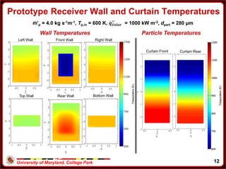
Prototype-Scale Receiver Model Parameters
Geometry Lx (m) Ly (m) Lz (m)
Receiver – r 1.85 5.00 1.50
Aperture – a 1.00 3.00 -
Curtain – c 1.00 5.00 Δzcurt
Property Units Baseline Range
dp μm 280 [100, 700]
ṁ’p kg s-1m-1 2.0 [1.0, 4.0]
εp
[4] - 0.85 [0.1-1.0]
Tp,in K 600 [300, 1100]
𝒒 𝑺𝒐𝒍𝒂𝒓
′′ kW m-2
1000 [100, 1500]
ρp
[4] kg m-3 3560 -
Cp,p
[4] J kg-1K-1 264+2.07T-1.12e-3T2
[4] Siegel, N., et al. (2010). J. of Sol. Energy Eng., 132.
λ range (μm) εwall,λ
[4]
0-4.5 0.20
4.5-∞ 0.80
11](https://image.slidesharecdn.com/ef5c2ee7-e053-4f9b-a865-a1500135af40-160504023507/85/Dissertation-Defense-Final-11-320.jpg)

![University of Maryland, College Park
• Prototype-scale results demonstrate need for high flow rates and
longer falls to achieve higher Tp,out while maintaining high ηsolar.
• Sandia National Labs[5] have been studying large, commercial-scale
receivers at their solar field facility.
• It is important to assess performance trade-offs at these larger
commercial scales before large-scale investments can be made for
plants using particle receivers.
• Commercial-scale receiver design requires evaluation of important
operating parameters for further development
– Impact of εp on performance
– Advantages of selective absorption, with εp in solar spectra and low εp at
longer wavelength
Commercial-scale Particle Receiver Simulations
[5] Ho,C. (2014). Personal Communication.
15](https://image.slidesharecdn.com/ef5c2ee7-e053-4f9b-a865-a1500135af40-160504023507/85/Dissertation-Defense-Final-15-320.jpg)
![University of Maryland, College Park
Ly,r
Ly,a
x
y
z
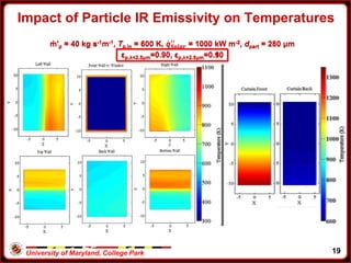
Commercial-Scale Receiver Model Parameters
Geometry Lx (m) Ly (m) Lz (m)
Receiver – r 12 21 15
Aperture – a 11 20 -
Curtain – c 11 21 tcurt
Property Units Baseline
dp μm 280
ṁ’p kg s-1m-1 40
ρp
[4] kg m-3 3560
Cp,p
[4] J kg-1K-1 264+2.07T-1.12e-3T2
Tp,in K 600
𝒒 𝑺𝒐𝒍𝒂𝒓
′′ kW m-2
1000
16
λ range (μm) εp,λ εwall,λ
[4]
0-2.5 0.1-0.9 0.2
2.5-4.5 0.1-0.9 0.2
4.5-∞ 0.1-0.9 0.8](https://image.slidesharecdn.com/ef5c2ee7-e053-4f9b-a865-a1500135af40-160504023507/85/Dissertation-Defense-Final-16-320.jpg)


![University of Maryland, College Park
• Undoped and doped ceria has been proposed by many authors[6-10]
for solar thermochemical fuel production because it:
– Preserves its (flourite) crystal structure under large degrees of
reduction, δ
– Maintains thermal stability with melting temperature >2800 K
– Exhibits high catalytic activity for H2O and CO2 reduction
• Lab-scale tests have demonstrated the capability to reliably yields H2
or CO, but have had trouble identifying practical receiver geometries
Ceria as a Solar Material
Parameter Value
ρpart (kg/m3)
7215 (Ce2O4)
6200 (Ce2O3)
cp,part (J/kg-K) ~460[11]
kpart (W/m-K) 12.0[11]
λ range
(μm)
frad (%)
Solar
εp,λ
[10]
Solar
frad (%)
1600 K
εp,λ
[10]
1600K
0-0.6 31 0.57 0 0.36
0.6-1.25 54 0.26 7 0.17
1.25-3.5 15 0.09 64 0.08
3.5-∞ 0 0.51 29 0.34
[6] Chueh, W, & Haile, S. (2010) Phil. Trans. Roy. Soc A, 368.
[7] Scheffe, J., Steinfeld, A. (2012) Energy & Fuels, 26.
[8] Lapp et al. (2012) Energy, 37.
[9] Le Gal et al. (2011). Energy & Fuels, 25.
[10] Marabelli & Wachter. (1987) Phys. Rev. B., 36.
[11] Mogensen et al. (2000). Sol. State. Ion., 129.
22](https://image.slidesharecdn.com/ef5c2ee7-e053-4f9b-a865-a1500135af40-160504023507/85/Dissertation-Defense-Final-22-320.jpg)
![University of Maryland, College Park
Ceria Modeling
δb
δsb
δs
Diff. R1 R2
• Species fractions related to δ:
Diffusion
Ce2O4(b) + Ce2O3(sb) ↔ Ce2O3(b) +Ce2O4(sb)
D∞ = 1.0 e-4 m2/s [12] Ea,diff = 333.4 kJ/kmol [12]
δρ
δρ
2VOCe
21OOCe
0
O32
0
O42
-
dr
μd
TR
ρD
j OOO
diff
0
23
Reverse Incorporation
Ce2O4(sb) + VO(s) ↔ OO(s) + Ce2O3(sb)
kfwd,R1 = 3e6 kmol/s[13] βR1 = 0.5[13]
Surface Exchange
2 OO(s) ↔ O2(g)+2 VO(s)
σO2 = 0.75[14] βR2 = 0.5[13]
TR
Xk
TR
Xkn
ex
ssbred
ex
ssbred
,R1
(sb)OCeO(s)R1rev,
,R1
(sb)OCe(s)VR1fwd,R1
exp+
1
exp
32
42O
TRTRW
P
TR
kn
ex
sred,R22
(s)V
O
O
O
ex
sred,R22
O(s)R2fwd,R2
exp
2
1
exp2
O
2
2
2
[12] Giordano et al. (2011). Energy & Fuels, 25. [13] DeCaluwe et al. (2010). J. Phys. Chem, 114.
[14] Leistner et al. (2012) Appl. Cat. B, 415.](https://image.slidesharecdn.com/ef5c2ee7-e053-4f9b-a865-a1500135af40-160504023507/85/Dissertation-Defense-Final-23-320.jpg)
![University of Maryland, College Park
0.0001
0.001
0.01
0.1
1
1.E-321.E-281.E-241.E-201.E-161.E-121.E-081.E-041.E+00
δinCeO2-δ
1773
1673
1573
1473
1373
1273
1173
1073
973
873
• Zinkevich et al. (2010) model incorrectly accounted for δ dependence
– Corrected Zinkevich model correctly models T >1000 K
– Corrected Zinkevich model has reasonable low-T performance
• Surface thermodynamics fit ∆𝒉 𝒓𝒆𝒅,𝒔
𝟎
− ∆𝒉 𝒓𝒆𝒅,𝒃
𝟎
and ∆𝒔 𝒓𝒆𝒅,𝒔
𝟎
− ∆𝒔 𝒓𝒆𝒅,𝒃
𝟎
by using in-situ XPS data of DeCaluwe et al. (2011)
Thermodynamic Model
Equilibrium PO2 (atm) compared to experimental values[12]
24](https://image.slidesharecdn.com/ef5c2ee7-e053-4f9b-a865-a1500135af40-160504023507/85/Dissertation-Defense-Final-24-320.jpg)

![University of Maryland, College Park
Ly,r
Ly,a
x
y
z
Prototype-Scale Receiver Model Parameters
Geometry Lx (m) Ly (m) Lz (m)
Receiver – r 1.85 5.00 1.50
Aperture – a 1.00 3.00 -
Curtain – c 1.00 5.00 tcurt
Property Units Baseline Range
dp μm 300 [200, 700]
ṁ’p kg s-1m-1 2.0 [1.0, 4.0]
Tp,in K 1100 [1000, 1400]
𝒒 𝑺𝒐𝒍𝒂𝒓
′′ kW m-2
1000 -
PO2,in atm 1·(10-5) -
26
λ range (μm) εwind,λ
[15] ρwind, λ
[15] εwall,λ
[4]
0-0.6 0.00 0.073 0.20
0.6-1.25 0.00 0.071 0.20
1.25-3.5 0.046 0.068 0.20
3.5-∞ 0.91 0.011 0.80
[15] Heraeus. (2007).](https://image.slidesharecdn.com/ef5c2ee7-e053-4f9b-a865-a1500135af40-160504023507/85/Dissertation-Defense-Final-26-320.jpg)


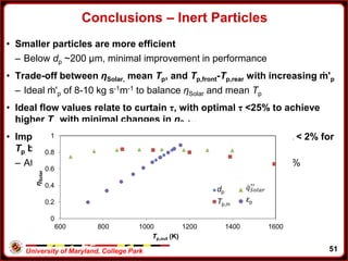
![University of Maryland, College Park
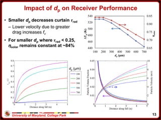
• Smaller particles capture more energy chemically
– Greater surface area and Tp
• Reactive particles can achieve higher ηSolar than inert particles
• Particles much lower than 300 μm can have stability problems[4]
Impact of dp and reaction on performance
Chem
Solar
k
k
Sensible η
Q
hmhm
η
tot
1
kout,kout,kin,kin,
Solar
n
i
ipreac
O
ireactg
Chem
Q
Th
W
m
η
cells
1
,
,,
Δ
2
0
0.05
0.1
0.15
0.2
0.25
100 200 300 400 500 600 700
Efficiency
dP (μm)
ηSensible ηChem ηInert
30](https://image.slidesharecdn.com/ef5c2ee7-e053-4f9b-a865-a1500135af40-160504023507/85/Dissertation-Defense-Final-30-320.jpg)
![University of Maryland, College Park
• Receiver design is not optimized for ceria production
– To achieve high Tp at this scale requires low ṁ'p
• Design requires evaluation in context of a full-system
– Strategies for power production or heat recovery
• Undoped ceria performance is low due to very high Tp and low εp
– Doping strategies being explored, but face challenges due to cycling
and slow oxidation kinetics. [6,8-10]
• Lower-Tp cycles with better optical properties can achieve higher
performance
• Perovskites are a class of materials with similar solid-structures and
high εp
– Favorable reduction thermodynamics at much lower temperatures
– Cannot be used for fuel production
Ceria conclusions and perovskite motivation
31](https://image.slidesharecdn.com/ef5c2ee7-e053-4f9b-a865-a1500135af40-160504023507/85/Dissertation-Defense-Final-31-320.jpg)
![University of Maryland, College Park
Surface Exchange
2 OO(s) ↔ O2(g)+2 VO(s)
ksurf,∞ = 0.109 m/s [18] Ea,surf =74.30 kJ/mol [18]
La0.1Sr0.9Co0.8Fe0.2O3-δ Particle Model
δb
δs
Diffusion
Surf
Exch.
• Species fractions related to δ:
Diffusion
LSCFO3(b) + VO(s) ↔ LSCFO2(b) + OO(s)
D∞ = 1.01e-4 m2/s [18] Ea,diff = 55.96 kJ/mol [18]
dr
μd
TR
ρD
an OOO
partdiff
0
= ( )sseqsurfsurf kn δδρ -,
0
=
Parameter Value
ρpart (kg/m3)
6580[16] (LSCFO3)
6051[16] (LSCFO2)
cp,part (J/kg-K) 145[16]
ε (-) 0.90[17]
[16]: Beale, S. et al. (2011). ECS Transaction, 35: 935-943.
[17]: Guar, A. et al. (2013) Euro. Fuel Cell Conf.
[18]: Choi, M. et al. (2011). Sol. State Ionics, 11: 269-274.
[ ] [ ] ( )
[ ] [ ] δρ
δρ
0
O20.20.80.90.1
0
O30.20.80.90.1
VOFeCoSrLa
1OOFeCoSrLa
==
== -
32](https://image.slidesharecdn.com/ef5c2ee7-e053-4f9b-a865-a1500135af40-160504023507/85/Dissertation-Defense-Final-32-320.jpg)
![University of Maryland, College Park
• Assume ΔHO(δ) and ΔSO(δ) are constant with temperature[19]
• Ideal thermodynamics fit to NASA Polynomial (Ref. state: δ0 =0.45)
LSCF Thermodynamics
ΔHO = -433.27δ - 55.835
ΔSO = -76.414δ - 168.78
1000 °C
950 °C
900 °C
800 °C
1000 °C
950 °C
900 °C
800 °C
OO
eqO
OeqOOLSCFOLSCFO μTμ
P
P
RTTμPTμδTμδTμ Δ
2
1
ln
2
1
,
2
1
,-, 0
0
,0
, 2
2
22223
[19]: Choi, M. et al. (2012). Sol. State Ionics, 12: 22-27.
33](https://image.slidesharecdn.com/ef5c2ee7-e053-4f9b-a865-a1500135af40-160504023507/85/Dissertation-Defense-Final-33-320.jpg)


![University of Maryland, College Park
• Solves for radiation intensity, Iλ, at every location and in specified
directions, θ and φ
• Directions determined by splitting Cartesian grid into Nθ x Nφ
discretizations in each octant
• Particle source terms determined by collecting contributions from
each injection
Discrete Ordinates (DO) Radiation Model
')'(',,, , ΩΦ
4
4
0
2
dsssrI
π
σ
SrInasrIσaassrI
π
λ
pI
pλλbλλppλλ
cell
pp
drops
p
p
V
t
εd
π
n
N
da
Δ
4
2
cell
pσp
drops
p
p
V
t
εfd
π
n
N
σd
Δ
11
4
2
cell
pppλ
drops
pI
pλ
V
t
Tεaf
n
N
dS m
Δ4
,
Property Value
𝒒 𝑺𝒐𝒍𝒂𝒓
′′
(kW m-2) 917.8
Beam Direction [0, 0, -1]
Beam Width
Δθ x Δφ (deg)
0.001 x 0.001
Diffuse Fraction 0.0
Property Value
Nθ x Nφ 9 x 5
𝑵 𝜽 𝒑
x 𝑵 𝝋 𝒑 7 x 7
Δλ1 (μm) [0, 4.5]
Δλ2 (μm) [4.5, 100]
42](https://image.slidesharecdn.com/ef5c2ee7-e053-4f9b-a865-a1500135af40-160504023507/85/Dissertation-Defense-Final-42-320.jpg)
![University of Maryland, College Park
Prototype-Scale Run Parameters
Lx (m) Ly (m) Lz (m)
Receiver – r 1.85 5.00 1.50
Aperture – w 1.00 3.00 -
Curtain – c 1.00 - 0.01
Gas Inlet - i 1.00 - 0.10
Property Units Baseline Range
dpart μm 300 [200, 500]
ṁ'part kg s-1m-1 2.0 [2.0, 4.0]
Tin K 1100 -
εp - 0.3347 -
PO2,in atm 1·(10-5) -
ug,in m/s 1.0 -
𝒒 𝑺𝒐𝒍𝒂𝒓
′′ kW m-2
917 -
λ range (μm) εWall,λ
[4]
0-4.5 0.20
4.5-∞ 0.80 Lc,z
Li,z
Lc,x
Lagrangian Particle Injection
Locations
43](https://image.slidesharecdn.com/ef5c2ee7-e053-4f9b-a865-a1500135af40-160504023507/85/Dissertation-Defense-Final-43-320.jpg)


![Boechler nicholas[1]](https://cdn.slidesharecdn.com/ss_thumbnails/boechlernicholas1-140830024557-phpapp02-thumbnail.jpg?width=640&height=640&fit=bounds)


