This paper presents a novel method for digital video camera identification using green-channel photo response non-uniformity (g-prnu) as a fingerprint. By extracting the green channel from video frames and applying a wavelet-based denoising technique, the authors demonstrate that g-prnu offers higher identification accuracy compared to traditional prnu methods. The results indicate that g-prnu can achieve a 99.15% success rate in identifying video sources from a diverse dataset of consumer cameras and mobile phones.
![Dhinaharan Nagamalai et al. (Eds) : ICCSEA, SPPR, UBIC - 2016
pp. 47–57, 2016. © CS & IT-CSCP 2016 DOI : 10.5121/csit.2016.61105
DIGITAL VIDEO SOURCE IDENTIFICATION
BASED ON GREEN-CHANNEL PHOTO
RESPONSE NON-UNIFORMITY (G-PRNU)
M.Al-Athamneh1
, F.Kurugollu2
, D.Crookes3
and M. Farid4
The Institute of Electronics, Communications and Information Technology
(ECIT),
Queen’s University Belfast.
123
{malathamneh01, f.kurugollu, d.crookes} @qub.ac.uk
4
Department of Electronics, Computing and Mathematics
University of Derby
m.farid@derby.ac.uk
ABSTRACT
This paper proposes a simple but yet an effective new method for the problem of digital video
camera identification. It is known that after an exposure time of 0.15 seconds, the green
channel is the noisiest of the three RGB colour channels [5]. Based on this observation, the
digital camera pattern noise reference, which is extracted using only the green channel of the
frames and is called Green-channel Photo Response Non-Uniformity (G-PRNU), is exploited as
a fingerprint of the camera. The green channels are first resized to a standard frame size
(512x512) using bilinear interpolation. Then the camera fingerprint is obtained by a wavelet
based denoising filter described in [4] and averaged over the frames. 2-D correlation
coefficient is used in the detection test. This method has been evaluated using 290 video
sequences taken by four consumer digital video cameras and two mobile phones. The results
show G-PRNU has potential to be a reliable technique in digital video camera identification,
and gives better results than PRNU.
KEYWORDS
PRNU, G-PRNU, Video Forensics.
1. INTRODUCTION
The first legislation which recognized computer crime was in 1978 (Florida Computer Crimes
Act), which was against the unauthorized modification or deletion of data on a computer system.
Since then, ‘Digital Evidence’ has become a new type of evidence in the judicial system.
Digital evidence has increased tremendously in the last few decades, as courts of law allow the
use of e-mails, digital photographs, digital video or audio files, ATM transaction logs, word
processing documents, spread-sheets, internet browser histories, computer memory contents,
computer backups, and Global Positioning Systems tracks.](https://image.slidesharecdn.com/csit65805-161008054810/75/DIGITAL-VIDEO-SOURCE-IDENTIFICATION-BASED-ON-GREEN-CHANNEL-PHOTO-RESPONSE-NON-UNIFORMITY-G-PRNU-1-2048.jpg)
![48 Computer Science & Information Technology (CS & IT)
As with any other type of evidence presented to the court of law, digital evidence is subjected to
integrity and authenticity checks. An integrity check aims to ensure that the act of seizing did not
modify the evidence; authenticity refers to the ability to confirm the trustworthiness of presented
evidence; e.g. to show it has not been tampered with.
Digital videos were introduced commercially in 1986 with the Sony D-1 format. Since then they
have experienced enormous growth, and have been used in a growing number of applications.
They can be found everywhere in today’s daily life like consumer digital video cameras, mobile
phones, CCTV cameras, DVDs, internet, etc. Research topics in digital video forensics include
source camera identification, device linking, authentication, integrity verification, etc. It has
become an emerging field due to the availability of sophisticated video editing tools, and because
of the lack of methodologies for validating the source of digital videos.
Identifying the device used in acquiring a particular digital video is important, as it can be used as
a definitive proof (or disproof) of events in a court of law. It can be likened to firearm forensics,
in which the imperfections in the surface of the interior of the barrel create cracks on the
projectiles which produce a unique “bullet scratch” pattern on every bullet that passes through the
barrel of the firearm. The equivalent of “bullet scratch” in digital forensics is the Photo Response
Non-Uniformity (PRNU).
Extracting PRNU is very sensitive process as the PRNU is a weak signal and can be manipulated
easily by the content in the digital data, previous research has shown that by including a
weighting factor during PRNU extraction can improve the correct identification, by using the
weighting factor smooth regions are emphasized, edges and highly-texture regions are
deemphasized during the denoising process [23].
Other research worked on enhancing the estimation of PRNU using probabilistically estimated
raw data to obtain better camera identification for small dimension patches, Poisson process and
Maximum Likelihood Estimation (MLE) is used to extract the PRNU [21].
Not only in the field of source identification and manipulation detection , PRNU can also be
used to improve a biometric systems Security by ensuring the authenticity and integrity of
images acquired with a biometric sensor [22].
In a digital video camera the light passes through a colour filter array (CFA), which is positioned
over the sensor to separate out the red, green, and blue components of light falling on it. The
GRGB Bayer Pattern is the most common CFA used in digital video cameras as depicted in
Figure 1; this process produces the digital video frame, which can be represented by a matrix of
RGB values.](https://image.slidesharecdn.com/csit65805-161008054810/75/DIGITAL-VIDEO-SOURCE-IDENTIFICATION-BASED-ON-GREEN-CHANNEL-PHOTO-RESPONSE-NON-UNIFORMITY-G-PRNU-2-2048.jpg)
![Computer Science & Information Technology (CS & IT) 49
Figure 1. The digital video frame acquisition process.
Previous research has shown that the relationship between the PRNU and the exposure time is
approximately linear, and that the green channel has the highest PRNU, followed by the red and
then the blue channels respectively. After an exposure time of 0.15s the green channel is the
noisiest channel among the three colours RGB [5].
In this paper, a new method for digital video source identification using Green-Channel PRNU
(G-PRNU) is proposed. First the frames are resized to 512x512 using bilinear interpolation, to
facilitate calculating 2-D correlation between different video sequences. Then the noise in the
resized frames is obtained using a wavelet-based denoising filter [4]. The camera fingerprint is
obtained by averaging the noise over all frames. Performance of green channel only PRNU in
video sequences is superior to ordinary PRNU. Moreover the use of bilinear interpolation for
resizing also improves the performance of the proposed method.
The rest of the paper is organised as follows: PRNU is introduced in the next section. Section 3
presents G-PRNU and explains how the camera reference is extracted. The bilinear interpolation
and noise detection strategy are also discussed in this section. The results are presented in Section
4 and the conclusions are drawn in Section 5.
2. PHOTO RESPONSE NON-UNIFORMITY (PRNU)
PRNU can be simply defined as: The imperfections of manufacturing semiconductor wafers, and
the variations in which individual sensor pixels create a sensor-specific noise pattern which
makes it possible to identify the imaging source. Its reliability in identifying devices and related
models has been demonstrated [3,9,10,12,14,18,19,20].
The PRNU method creates the digital camera reference (the consistent noise pattern of each
sensor pixel) by finding the noise in captured images, and averaging this noise over a set of
images to give the camera reference. The noise can be estimated by denoising the original
images.
PRNU has proved to be an effective technique for determining the source of a digital image (the
‘suspected image’) using the following steps:](https://image.slidesharecdn.com/csit65805-161008054810/75/DIGITAL-VIDEO-SOURCE-IDENTIFICATION-BASED-ON-GREEN-CHANNEL-PHOTO-RESPONSE-NON-UNIFORMITY-G-PRNU-3-2048.jpg)
![50 Computer Science & Information Technology (CS & IT)
• Create the digital camera reference, by averaging the noise obtained by, for example, a
Wavelet based denoising algorithm.
• Create the suspected image reference: this image reference is the noise obtained by using the
previous denoising technique.
• Finally, apply a camera reference detection method, by matching the suspected image
reference against a set of camera reference images. The main detection methods are:
normalized correlation coefficient, the peak to correlation energy (PCE) and correlation to
circular correlation norm (CCN) [9,16].
3. G-PRNU CAMERA REFERENCE
3.1. G-PRNU EXTRACTION
Most previous research has focused on still images, while modern forensic applications are
mostly based on digital videos rather than still images (CCTV, camcorders, cell-phones, etc.);
therefore our aim in this paper is to create an effective method to determine the source of a digital
video. The motivation behind this is the need to authenticate digital video evidence and prove its
trustworthiness in a court of law.
Because the green colour channel of video frames is normally noisier than the other colour
channels, G-PRNU (Green - Photo Response Non-Uniformity) was created by examining the
green colour channel of the video frames.
′ = ࢌ() (1)
Where ′ܣ is the denoised digital video frame (k),ܣis the actual captured frame and f is the
denoising function [4].
The actual noise can then be extracted from frame k:
ࡺ = − ′ (2)
Where ܰ is the frame (k) noise. Then we average this over a set of captured frames:
࢟ =
∑ ࡺ
స
(3)
Where y is the digital video G-PRNU reference, l is the total number of frames (in our case, 350
frames per video).](https://image.slidesharecdn.com/csit65805-161008054810/75/DIGITAL-VIDEO-SOURCE-IDENTIFICATION-BASED-ON-GREEN-CHANNEL-PHOTO-RESPONSE-NON-UNIFORMITY-G-PRNU-4-2048.jpg)
![Computer Science & Information Technology (CS & IT) 51
Figure 2. G-PRNU reference of Canon IXUS 8515 (C2), Note: The reference image is x6 scaled for
viewing purpose.
Figure 3. G-PRNU reference of Huawei Ascends G300 (C6), Note: reference image is x6 scaled for
viewing purpose.
The difference in G-PRNU camera reference for two different cameras can be visually noted: in
Figure 2, note the greater level of noise at the left edge of the reference image, while in Figure 3
the noise is more smoothly distributed with little bit more noise on the right edge.
3.2. FRAME RESIZING
When comparing videos potentially from a range of different cameras, the question of frame size
was encountered. Even a single camera can produce a range of frame sizes. Also, the suspected
videos may have been resized. Therefore, all reference images are resized to a standard size (for
example, 512x512 is used), for comparison using 2-D correlation. This should be carried out with
extra care avoiding any damage of the characteristic noise patterns.
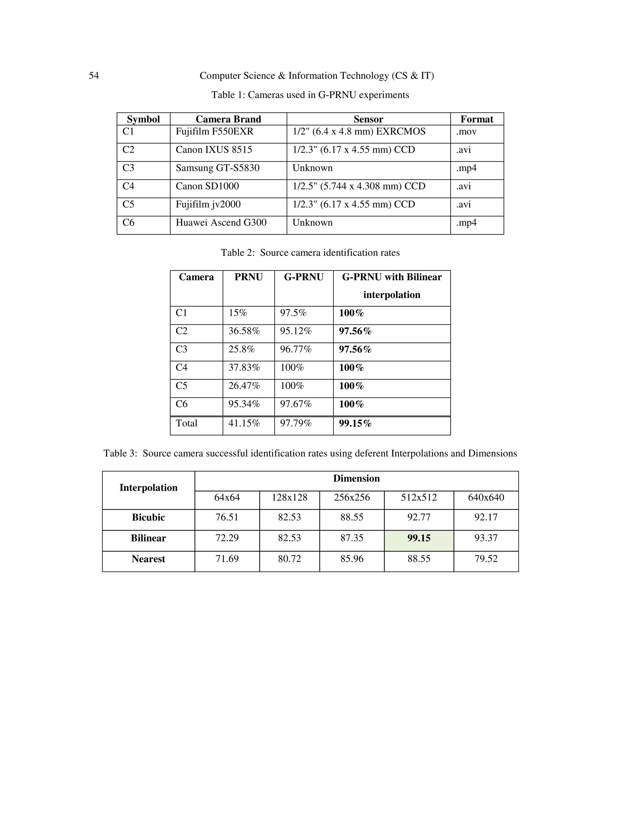
Bilinear Interpolation which is an extension of linear interpolation was used in this work where
the output (interpolated) pixel value is a weighted average of pixels in the nearest 2x2
neighbourhood, This results in much smoother looking images than Nearest Neighbor and
Bicubic interpolation which they were experimentally used in this work but yet Bilinear
Interpolation proved to give the best correlation results [Table 3].](https://image.slidesharecdn.com/csit65805-161008054810/75/DIGITAL-VIDEO-SOURCE-IDENTIFICATION-BASED-ON-GREEN-CHANNEL-PHOTO-RESPONSE-NON-UNIFORMITY-G-PRNU-5-2048.jpg)
![52 Computer Science & Information Technology (CS & IT)
CALCULATING BILINEAR INTERPOLATION
Figure 4. Bilinear Interpolation calculating method
There are several equivalent ways to calculate the value of the bilinear interpolation P. An easy
way to calculate the value of P would be to first calculate the value of the two blue dots, R2, and
R1. R2 is effectively a weighted average of Q12 and Q22, while R1 is a weighted average of Q11
and Q21.
R1 = ((x2 – x)/(x2 – x1))*Q11 + ((x – x1)/(x2 – x1))*Q21
R2 = ((x2 – x)/(x2 – x1))*Q12 + ((x – x1)/(x2 – x1))*Q22
After the two R values are calculated, the value of P can finally be calculated by a weighted
average of R1 and R2.
P = ((y2 – y)/(y2 – y1))*R1 + ((y – y1)/(y2 – y1))*R2
There are two main reasons for using bilinear interpolation over other methods: first it helps to
get better correlation [Table 2], and second it solves the matrix dimension mismatch problem
which deters the calculation of 2-D correlation coefficients.
3.3. G-PRNU DETECTION
Applying an effective detection method for camera identification is no less important than
constructing the camera reference in the first place. Some researchers have used the normalized
correlation coefficient for this purpose [1,2,6] while others have shown that the peak to
correlation energy (PCE) can give better results in detection tests [8,9]. Furthermore circular
correlation norm (CCN) [10] has also been used as a statistical detection test which basically
enhances the results of PCE by lowering the false positive rates.
In this research the 2-D correlation coefficient was used in the camera detection test, which
computes the correlation coefficient between the video camera reference (A) and the suspected
video reference (B), where A and B are G-PRNU matrices of the same size.](https://image.slidesharecdn.com/csit65805-161008054810/75/DIGITAL-VIDEO-SOURCE-IDENTIFICATION-BASED-ON-GREEN-CHANNEL-PHOTO-RESPONSE-NON-UNIFORMITY-G-PRNU-6-2048.jpg)
![Computer Science & Information Technology (CS & IT) 53
ܚ =
∑ ∑ (ۯܖܕିۯഥ)(۰ܖܕି۰ഥ)ܖܕ
ටቀ∑ ∑ (ۯܖܕିۯഥ)ܖܕ
ቁቀ∑ ∑ (۰ܖܕି۰ഥ)ܖܕ
ቁ
(4)
Aഥ and Bഥ are the mean of A, B respectively.
Overall the proposed G-PRNU method can be summarised as follows:
1. Extract the green channel frames from the video (350 frames/video).
2. Resize the extracted frames to [512x512] using bilinear interpolation.
3. Perform wavelet-based de-noising on these green channel frames (denoising by soft-
thresholding [4]).
4. Create the G-PRNU map for the video by averaging the results of step 3.
5. To create a camera reference, perform steps1-4 on 9 videos captured by the same camera.
6. Use the 2-D correlation coefficient as the camera detection test.
4. EXPERIMENTAL RESULTS
First, a dataset of videos taken by a range of consumer video cameras was constructed. To try to
simulate the real life cases of digital video forensics, four video cameras and two mobile phones
(Samsung GT-S5830 and Huawei Ascend G300) [Table 1] were considered. Over a period of
four months, these cameras were used to capture a total of 254 videos under various conditions:
indoors, outdoors, sunny days, rainy days, good lighting and poor lighting; some videos were
captured by two different cameras at the same time by holding them side by side.
The camera reference for each of the six cameras was calculated by selecting nine videos from
each camera; the remaining 236 videos used as the test data set.
The 2-D correlation coefficient detection test was applied to identify the source of each of the 236
test videos, by matching against all six video references, using PRNU, G-PRNU, and G-PRNU
interpolated by 512x512 bilinear interpolations. The results are shown in Table 2. This shows the
cameras' identification rates and proves that the G-PRNU approach gives considerable success in
identifying the source device of digital video. From a total of 236 test videos, G-PRNU could
correctly determine the source of 234 videos (correct detection rate was 99.15%);in comparison,
using PCE [9], the correct detection rate was 41.15%.Note, in creating PRNU references, the
same method was used as in creating the G-PRNU references.
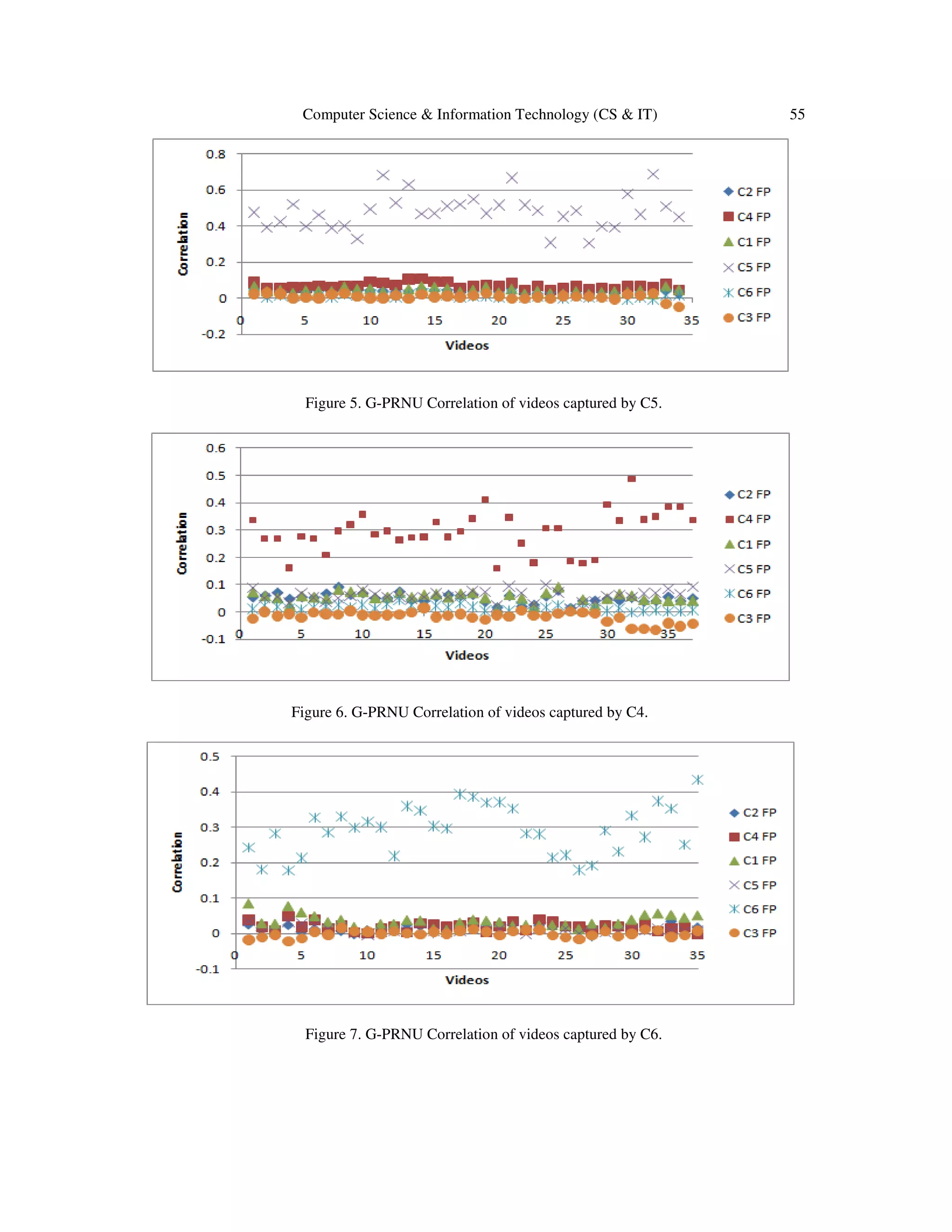
Figure 5 shows the 2-D correlation of videos captured by C4 versus the six cameras G-PRNU
fingerprints, all videos in figure 5 have obtained higher correlation with the C4 G-PRNU
fingerprint, this led to the conclusion that videos in figure 5 were captured by C4,figures 6 and 7
describe the same situation for C5 and C6, respectively.](https://image.slidesharecdn.com/csit65805-161008054810/75/DIGITAL-VIDEO-SOURCE-IDENTIFICATION-BASED-ON-GREEN-CHANNEL-PHOTO-RESPONSE-NON-UNIFORMITY-G-PRNU-7-2048.jpg)
![56 Computer Science & Information Technology (CS & IT)
5. CONCLUSIONS
A new method for video camera identification has been proposed, called G-PRNU. The method
was tested using six cameras (4 consumer cameras and two mobile phones). 290 videos were
captured under various conditions. In initial experiments, the G-PRNU method showed potential
to be a reliable technique in digital video camera identification and proven to give better results
than PRNU in the problem of digital videos source identification.
Also the question of frame size was encountered, as even a single camera can produce a range of
frame sizes, Frame resizing should be carried out with extra care avoiding any damage of the
characteristic noise patterns. The Bilinear Interpolation which is an extension of linear
interpolation gave results much smoother looking images and correct detection results than
Nearest Neighbor and Bicubic interpolation.
REFERENCES
[1] A. Popescu, and H. Farid, “Exposing Digital Forgeries in Color Filter Array Interpolated Images",
IEEE Transactions on Signal Processing, vol. 53, no. 10, pp.3948-3959,2005.
[2] A. Swaminathan, Min Wu, Liu, K.J.R., “Digital Image Forensics via Intrinsic Fingerprints”, IEEE
transactions on information forensics and security, vol. 3, Iss. 1, pp. 101-117, 2008.
[3] C. Li, "Source Camera Identification Using Enhanced Sensor Pattern Noise," IEEE Transactions on
Information Forensics and Security, vol. 5, no. 2, June 2010.
[4] D.L. Donoho, "De-noising by soft-thresholding," IEEE transactions on information theory, vol. 41,
no. 3, pp. 613–627, MAY 1995
[5] http://scien.stanford.edu/pages/labsite/2005/psych221/projects/05/joanmoh/prnu.html, [accessed Jan
2014]
[6] http://dde.binghamton.edu/download/, [accessed Jan 2014]
[7] J. R. Janesick,“Scientific Charge-Coupled Devices”, Bellingham, WA: SPIE, vol. PM83, 2001.
[8] J. Lukas, J. Fridrich, and M. Goljan, “Digital "bullet scratches" for images“, International Conference
on Image Processing (ICIP), IEEE, vol. 31, pp.65 – 68,2005.
[9] J. Lukas, J. Fridrich, and M. Goljan, "Digital Camera Identification from Sensor Noise," IEEE
Transactions on Information Security and Forensics, vol. 1, no. 2, pp. 205-214, 2006.
[10] J. Fridrich, “Digital image forensics”, IEEE signal processing, vol. 26, Iss. 2, pp.26-37, 2009.
[11] K.S Thyagarajan “Still image and video compression with MATLAB”, Wiley, 1st ed., 428p,2010.
[12] M. Chen, J. Fridrich, M. Goljan, and J. Lukas, "Determining Image Origin and Integrity Using Sensor
Noise," IEEE Transactions on Information Security and Forensics, vol. 3, no. 1, pp. 74-90, 2008.
[13] M. Goljan, J. Fridrich, and T. Filler, “Large scale test of sensor fingerprint camera identification,” in
Proc. SPIE, San Jose, CA, Jan. 18–22,2009, vol. 7254, pp. 0I 1–0I 12, Electronic Imaging, Media
Forensics and Security XI.](https://image.slidesharecdn.com/csit65805-161008054810/75/DIGITAL-VIDEO-SOURCE-IDENTIFICATION-BASED-ON-GREEN-CHANNEL-PHOTO-RESPONSE-NON-UNIFORMITY-G-PRNU-10-2048.jpg)
![Computer Science & Information Technology (CS & IT) 57
[14] M. Goljan and J. Fridrich, “Digital camera identification from images Estimating false acceptance
probability” in Proc. 8th Int.Workshop Digital Watermarking, Busan, Korea, Nov. 10–12, 2008.
[15] R.C. Gonzalez, R.Woods, S. Eddins, “Digital image processing using MATLAB”, Gatesmark
Publishing, 2nd ed., 827p, 2009.
[16] X. Kang, Y. Li, Z. Qu, and J. Huang, “Enhancing Source Camera Identification Performance with a
Camera Reference Phase Sensor Pattern Noise”, IEEE Trans. Inform. Forensics Security, vol. 1,
APRIL 2012.
[17] Y. Q.Shi, and H. Sun, “Image and video compression for multimedia engineering: fundamentals,
algorithms, and standards”, CRC Press LLC, 480p, 2000.
[18] Min-Jen Tsai, Cheng-Liang Lai, Jung Liu, “Camera/Mobile Phone Source Identification for Digital
Forensics”, IEEE International Conference on Acoustics, Speech and Signal Processing (ICASSP),
Apr. 2007, Hawaii USA.
[19] E. Dirik, H. T. Sencar, and N. Memon, “Source camera identification based on sensor dust
characteristics,” in Proc. Signal Processing Applications Public Security Forensics, Apr. 11–13,2007,
pp. 1–6.
[20] Y. Long and Y. Huang, “Image based source camera identification using demosaicking,” in Proc.
IEEE 8th Workshop Multimedia Signal Processing, Oct. 2006, pp. 419–424.
[21] A. Mehrish, A. V. Subramanyam and S. Emmanuel, "Sensor Pattern Noise Estimation Using
Probabilistically Estimated RAW Values," in IEEE Signal Processing Letters, vol. 23, no. 5, pp. 693-
697, May 2016.
[22] L. Debiasi and A. Uhl, "Comparison of PRNU enhancement techniques to generate PRNU
fingerprints for biometric source sensor attribution," 2016 4th International Conference on Biometrics
and Forensics (IWBF), Limassol, 2016, pp. 1-6.
[23] K. f. Lau, N. f. Law and W. c. Siu, "Use of sensor noise for source identification," Noise and
Fluctuations (ICNF), 2015 International Conference on, Xian, 2015, pp. 1-6.](https://image.slidesharecdn.com/csit65805-161008054810/75/DIGITAL-VIDEO-SOURCE-IDENTIFICATION-BASED-ON-GREEN-CHANNEL-PHOTO-RESPONSE-NON-UNIFORMITY-G-PRNU-11-2048.jpg)