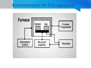
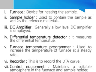
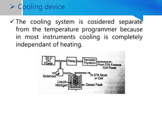
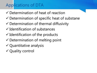
PRINCIPLE & INSTRUMENTATION
OF
DIFFERENTIAL THERMAL ANALYSIS
Anupriya N. R
1'st M Pharm
Dept. Quality Assurance
NGSMIPS
 A group of technique in which the physical
property is measured as a function of
temperature.
 The sample is subjected to a predefined heating
or cooling program.
Types Of Thermal Analysis
 Thermo gravimetric analysis
 Differential thermal analysis
 Differential scaning calorimetry
Thermal Analysis Technique
2
LeChatelier(1887)described a new technique for
the study of clay and minerals by the
of thier temperature time curves.
Robert-Austen(1899) improved the technique by
introducing two thermocouples.
Definition : Differential thermal analysis is a
thechnique in which the temperature difference
between the sample and a thermally inert
reference substance is continuously recorded as
fuction of temperature or time.
Differential Thermal Analysis
 Differential thermal analysis is also known as
thermography
 The measurement of change in heat content is
carried out by heating the two materials at
elevated temperature or cooling to subnormal
temperature at a predetermined rate.
The thermal effect associated with the
physical and chemical changes are measured
by a differential method in which the sample
temperature is continuously compared
against the temperature of thermally inert
material.
The differential temperature, ΔT is recorded
as a function of reference material
temperature or time , assuming that the
furnace temperature rise is linear with time.
Principle of working
 The thermal effects may be either endothermic
or exothermic.
 Enthalpic changes are caused by physical
phenomina such as fusion, crystalline structure
invertion , boiling, vapourisation, sublimation,
and others.
 Some enthalpic changes are also caused by
chemical reactions like decomposition, oxidation,
dehydration, reduction, compination,
displacement etc.
 The endo or exothermic bands and peaks
appearing on the thermogram give information
regarding the detection of enthalpic changes.
Instrumentation for DTA apparatus
i. Furnace : Device for heating the sample.
ii. Sample holder : Used to contain the sample as
well as the referece materials.
iii. DC Amplifier : Genarally a low level DC amplifier
is employed.
iv. Differential temperature detector : It measures
the differential temperatue.
v. Furnace temperature programmer : Used to
increase the temperature of furnace at a steady
rate.
vi. Recorder : This is to record the DTA curve.
vii. Control equipment : Maintains a suitable
atmosphere in the fuenace and sample holder.
Furnace
• Device for heating the sample.
• In DTA apparatus, tubular furnace is prefered.
• Constructed by appropriate material (wire or
ribbon) wound on a refractory tube.
• It possess desired characteristics for good
temperature regulation and programming.
• The choice of the resistant material and that of
refractory is decided from the intended maximum
temperatures of operation and gaseous
environment.
• The dimension depends up on the length of the
uniform temperature zone desired. The size of the
sample holder, heating rate and cost are also
 It used to contain the sample as well as the
reference material.
Material
• Both metalic and non-metalic materials are used
for the fabrication of sample holder.
• Metalic materials genarally include nickel,
stainless steal, platinum and its alloys.
-- metalic holders give rise to sharp exotherms
and
flat endotherms.
• Non-metalic matrials include glass, viterous
silica or sintered alumina.
--give rise to sharp endotherms and flat
 Sample Holders
Geometry
Temperature control
 The basic elements required are sensor, control
element and heater.
 Control element governs the rate of heat input
required to match the heat loss from the system.
 The two methods for controlling temperature:
i. On-off control: If the sensor-signal indicates that
the temperature has become greater than the
point, the heater is immediately cut off.
ii. Proportional control: The heat input to the
system progressively reduced as the temperature
aprroaches the desired value.
 Temperature controller and recorder
 It transmits certain time-based instruction to the
control unit.
 The simplest device is to use a variable speed
motor-driven autotransformer which gives a
power input to the furnace that is proportional
to the rate of movement of the drive mechanism.
 It can archive the linear rate of heating or
cooling if the autotransformer is driven in a non-
linear fation using a special cam-drive.
 Temperature programming
 Signals obtained from the sensors can be
recorded in which the signal trace is produced
on paper or film, by ink, heating stylus, electric
writing or optical beam.
 The two types of analogue recording modes are:
i. Deflection type : The recording pen is moved
directly by input signal.
ii. Null type: The input signal is compared with a
reference or standared signal and the difference
is amplified and used to adjust the reference
signal through a servo motor untill it matches
the input signal.
 Recorder
 They are the temperature sensors in most of the DTA and TG
instruments.
 The voltage signal produced between the two hetero-juntions
of the thermocouple depends up on the temperature
difference between these two junctions.
 The following points has to be considered while selecting the
thermocouples as the temperature sensor:Temperature
interval, Thermoelectric coefficient, Chemical compactibility
with the sample, availability and cost, chemical gaseous
environment used and reproducibility of the EMF vs
Temperature curve as a function of thermal cycling.
 Thermocouples
 Thermocouple made from the chromal P and alumel
wires (both nickel-chromium alloys) are used to
measure and control temperature up to 1100℃ in air.
 Above 1100℃, one should use thermocouple made
from pure platinum and platinum-rhodium alloy wires.
 Thermocouple fabricated from refractory material like
tungston and rhenium in inert gas or in vaccum for
temperature up to 2100℃.
 The cooling system is cosidered separate
from the temperature programmer because
in most instruments cooling is completely
independant of heating.
 Cooling device
 Determination of heat of reaction
 Determination of specific heat of substane
 Determination of thermal diffusivity
 Identification of substances
 Identification of the products
 Determination of melting point
 Quantitative analysis
 Quality control
Applications of DTA
B. K. Sharma, Instrumental methods of
chemical analysis, Goel Publishing House,
28th Edition, Pg no: M-318 to M-328.
Gurudeep R. Chatwal, Sham K Anand,
Instrumental method of chemical analysis.
Himalaya Publishing House. 5th ed, pg
no:2.719-2.738.
H. Kaur, Instrumental methods of chemical
analysis, Pragati Prakashan Educational
Publishers, 7th Edition, Pg no: 991.
References
Differential Thermal Analysis

Differential Thermal Analysis

  • 1.
    PRINCIPLE & INSTRUMENTATION OF DIFFERENTIALTHERMAL ANALYSIS Anupriya N. R 1'st M Pharm Dept. Quality Assurance NGSMIPS
  • 2.
     A groupof technique in which the physical property is measured as a function of temperature.  The sample is subjected to a predefined heating or cooling program. Types Of Thermal Analysis  Thermo gravimetric analysis  Differential thermal analysis  Differential scaning calorimetry Thermal Analysis Technique 2
  • 3.
    LeChatelier(1887)described a newtechnique for the study of clay and minerals by the of thier temperature time curves. Robert-Austen(1899) improved the technique by introducing two thermocouples. Definition : Differential thermal analysis is a thechnique in which the temperature difference between the sample and a thermally inert reference substance is continuously recorded as fuction of temperature or time. Differential Thermal Analysis
  • 4.
     Differential thermalanalysis is also known as thermography  The measurement of change in heat content is carried out by heating the two materials at elevated temperature or cooling to subnormal temperature at a predetermined rate.
  • 5.
    The thermal effectassociated with the physical and chemical changes are measured by a differential method in which the sample temperature is continuously compared against the temperature of thermally inert material. The differential temperature, ΔT is recorded as a function of reference material temperature or time , assuming that the furnace temperature rise is linear with time. Principle of working
  • 7.
     The thermaleffects may be either endothermic or exothermic.  Enthalpic changes are caused by physical phenomina such as fusion, crystalline structure invertion , boiling, vapourisation, sublimation, and others.  Some enthalpic changes are also caused by chemical reactions like decomposition, oxidation, dehydration, reduction, compination, displacement etc.  The endo or exothermic bands and peaks appearing on the thermogram give information regarding the detection of enthalpic changes.
  • 8.
  • 9.
    i. Furnace :Device for heating the sample. ii. Sample holder : Used to contain the sample as well as the referece materials. iii. DC Amplifier : Genarally a low level DC amplifier is employed. iv. Differential temperature detector : It measures the differential temperatue. v. Furnace temperature programmer : Used to increase the temperature of furnace at a steady rate. vi. Recorder : This is to record the DTA curve. vii. Control equipment : Maintains a suitable atmosphere in the fuenace and sample holder.
  • 10.
    Furnace • Device forheating the sample. • In DTA apparatus, tubular furnace is prefered. • Constructed by appropriate material (wire or ribbon) wound on a refractory tube. • It possess desired characteristics for good temperature regulation and programming. • The choice of the resistant material and that of refractory is decided from the intended maximum temperatures of operation and gaseous environment. • The dimension depends up on the length of the uniform temperature zone desired. The size of the sample holder, heating rate and cost are also
  • 11.
     It usedto contain the sample as well as the reference material. Material • Both metalic and non-metalic materials are used for the fabrication of sample holder. • Metalic materials genarally include nickel, stainless steal, platinum and its alloys. -- metalic holders give rise to sharp exotherms and flat endotherms. • Non-metalic matrials include glass, viterous silica or sintered alumina. --give rise to sharp endotherms and flat  Sample Holders
  • 12.
  • 13.
    Temperature control  Thebasic elements required are sensor, control element and heater.  Control element governs the rate of heat input required to match the heat loss from the system.  The two methods for controlling temperature: i. On-off control: If the sensor-signal indicates that the temperature has become greater than the point, the heater is immediately cut off. ii. Proportional control: The heat input to the system progressively reduced as the temperature aprroaches the desired value.  Temperature controller and recorder
  • 14.
     It transmitscertain time-based instruction to the control unit.  The simplest device is to use a variable speed motor-driven autotransformer which gives a power input to the furnace that is proportional to the rate of movement of the drive mechanism.  It can archive the linear rate of heating or cooling if the autotransformer is driven in a non- linear fation using a special cam-drive.  Temperature programming
  • 15.
     Signals obtainedfrom the sensors can be recorded in which the signal trace is produced on paper or film, by ink, heating stylus, electric writing or optical beam.  The two types of analogue recording modes are: i. Deflection type : The recording pen is moved directly by input signal. ii. Null type: The input signal is compared with a reference or standared signal and the difference is amplified and used to adjust the reference signal through a servo motor untill it matches the input signal.  Recorder
  • 16.
     They arethe temperature sensors in most of the DTA and TG instruments.  The voltage signal produced between the two hetero-juntions of the thermocouple depends up on the temperature difference between these two junctions.  The following points has to be considered while selecting the thermocouples as the temperature sensor:Temperature interval, Thermoelectric coefficient, Chemical compactibility with the sample, availability and cost, chemical gaseous environment used and reproducibility of the EMF vs Temperature curve as a function of thermal cycling.  Thermocouples
  • 17.
     Thermocouple madefrom the chromal P and alumel wires (both nickel-chromium alloys) are used to measure and control temperature up to 1100℃ in air.  Above 1100℃, one should use thermocouple made from pure platinum and platinum-rhodium alloy wires.  Thermocouple fabricated from refractory material like tungston and rhenium in inert gas or in vaccum for temperature up to 2100℃.
  • 18.
     The coolingsystem is cosidered separate from the temperature programmer because in most instruments cooling is completely independant of heating.  Cooling device
  • 19.
     Determination ofheat of reaction  Determination of specific heat of substane  Determination of thermal diffusivity  Identification of substances  Identification of the products  Determination of melting point  Quantitative analysis  Quality control Applications of DTA
  • 20.
    B. K. Sharma,Instrumental methods of chemical analysis, Goel Publishing House, 28th Edition, Pg no: M-318 to M-328. Gurudeep R. Chatwal, Sham K Anand, Instrumental method of chemical analysis. Himalaya Publishing House. 5th ed, pg no:2.719-2.738. H. Kaur, Instrumental methods of chemical analysis, Pragati Prakashan Educational Publishers, 7th Edition, Pg no: 991. References