Introduction
Conceptual Model of the EMS
EMS Functions and SCADA Applications.
Time decomposition of the power system operation.
Open Distributed system in EMS
OOPS
4
EMS
- Enhance thescope of SCADA by providing the power
application software to assist the operator in monitoring
and control of the electrical network.
It consists of three important phases:
1. Gathering Information: Acquisition of real-time data
and man machine information.
2. Decision Making.
3. Action by Transmitting Control Orders either
- Directly [Centralized Remote Control]
- Indirectly [Decentralized remote control or load
control].
5.
Conceptual Model ofEMS
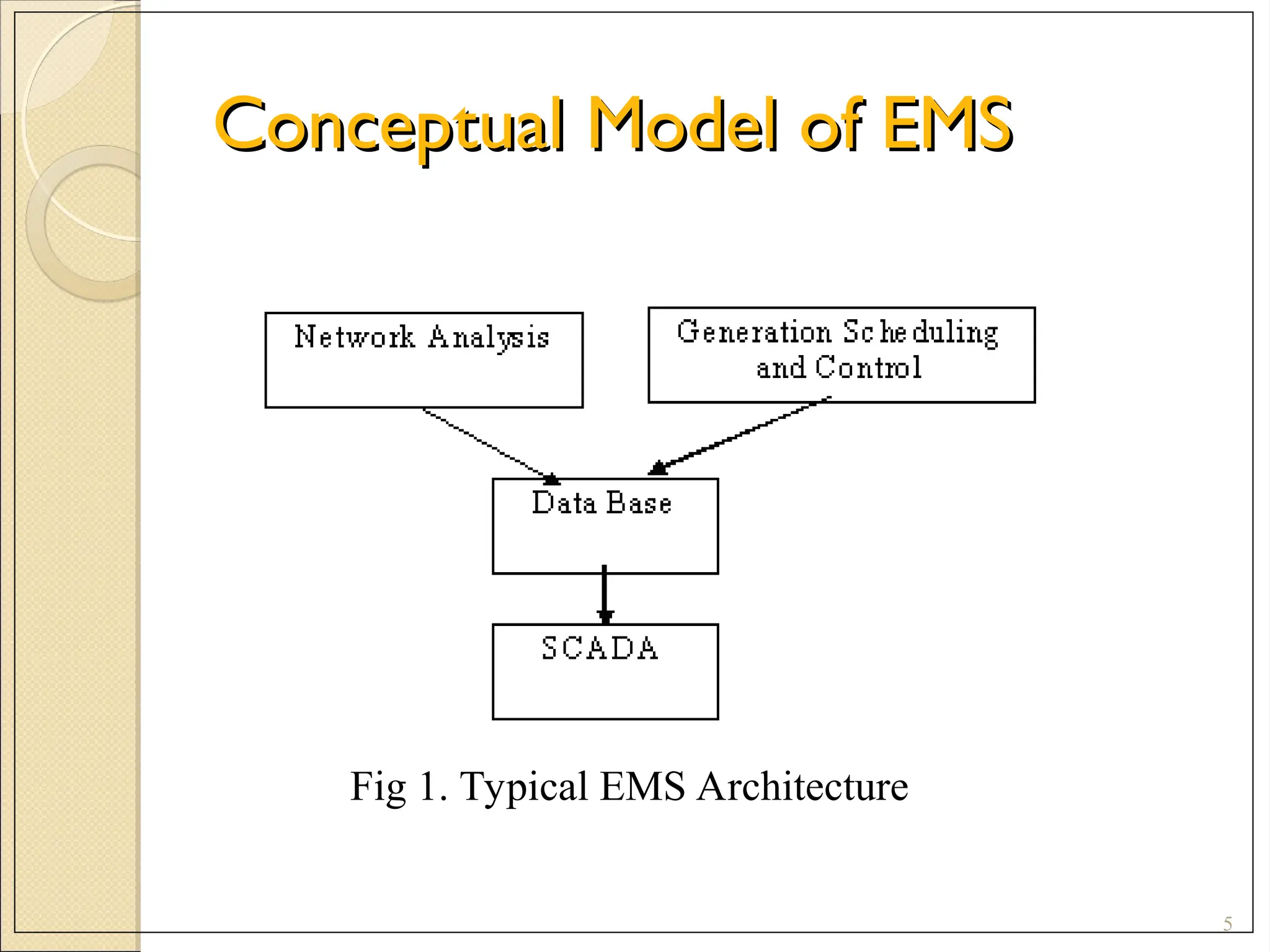
Conceptual Model of EMS
5
Fig 1. Typical EMS Architecture
6.
6
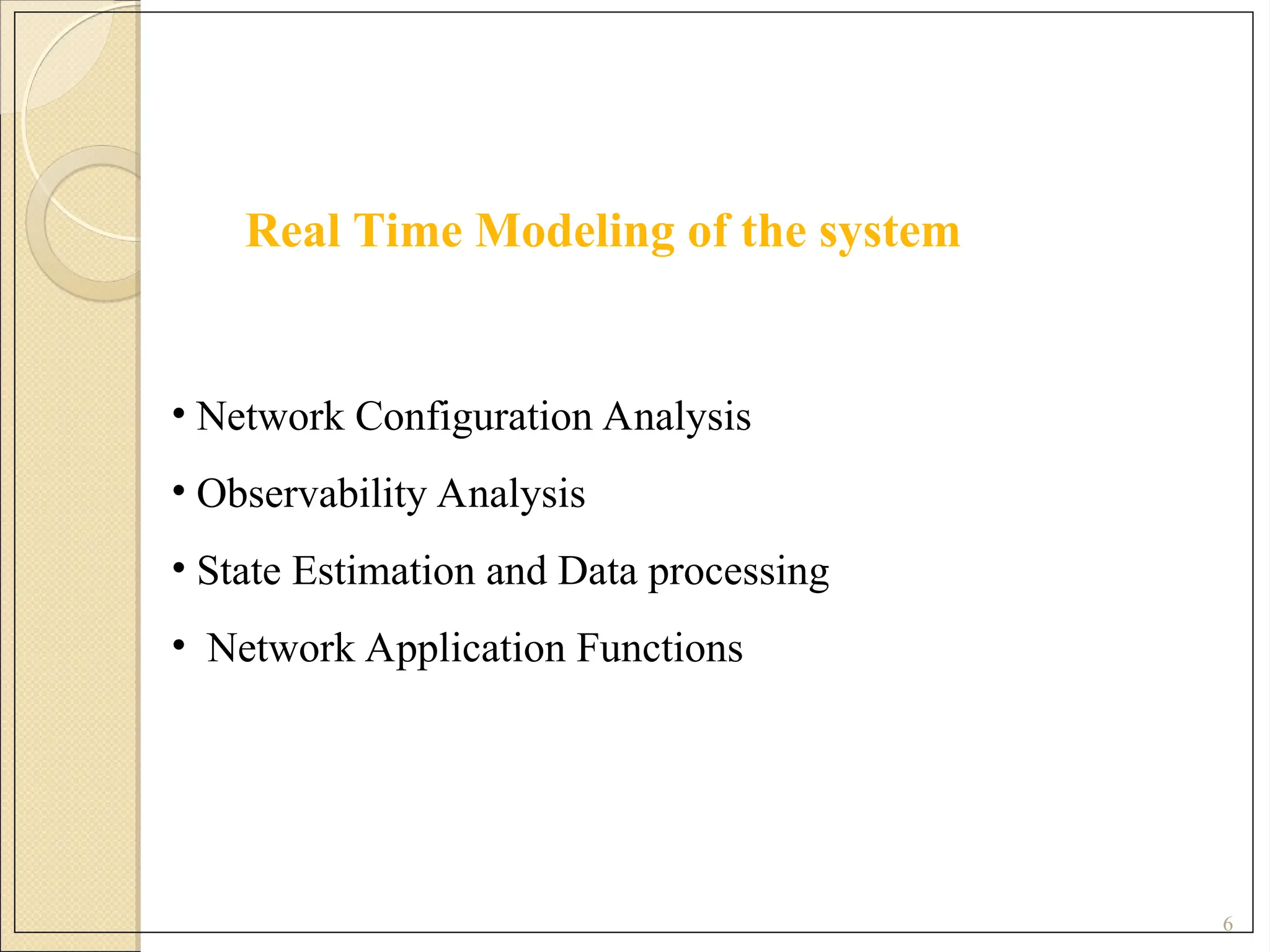
Real Time Modelingof the system
• Network Configuration Analysis
• Observability Analysis
• State Estimation and Data processing
• Network Application Functions
7.
EMS Application andSCADA Functions
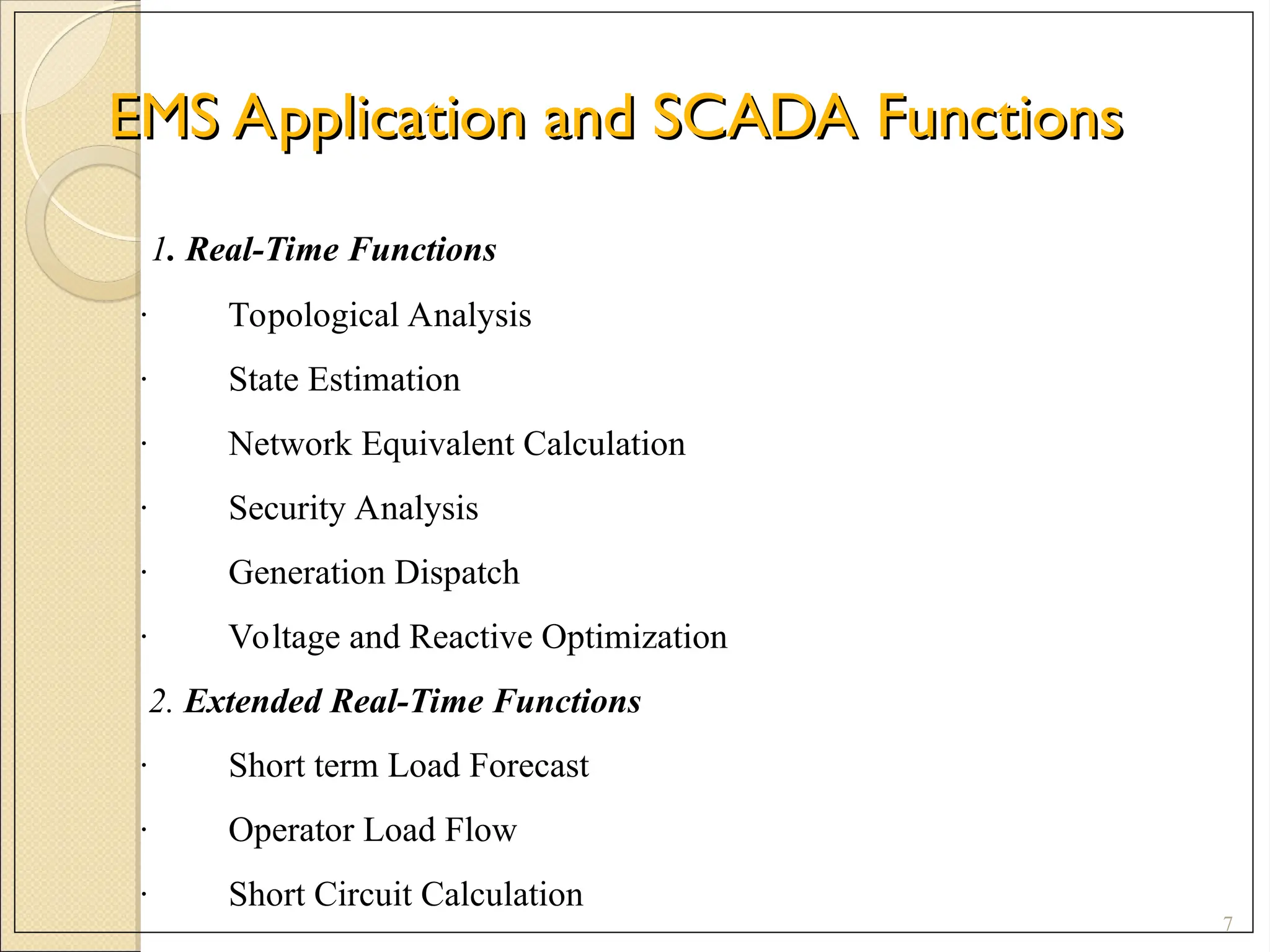
EMS Application and SCADA Functions
7
1. Real-Time Functions
· Topological Analysis
· State Estimation
· Network Equivalent Calculation
· Security Analysis
· Generation Dispatch
· Voltage and Reactive Optimization
2. Extended Real-Time Functions
· Short term Load Forecast
· Operator Load Flow
· Short Circuit Calculation
9
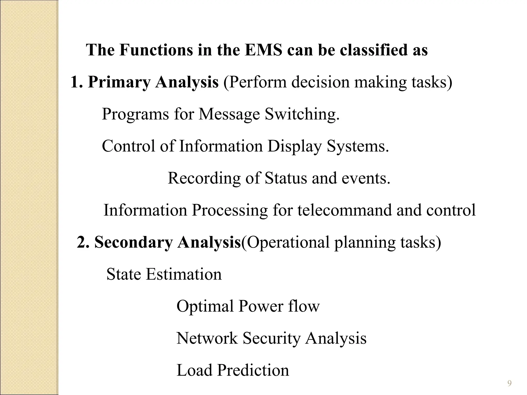
The Functions inthe EMS can be classified as
1. Primary Analysis (Perform decision making tasks)
Programs for Message Switching.
Control of Information Display Systems.
Recording of Status and events.
Information Processing for telecommand and control
2. Secondary Analysis(Operational planning tasks)
State Estimation
Optimal Power flow
Network Security Analysis
Load Prediction
10.
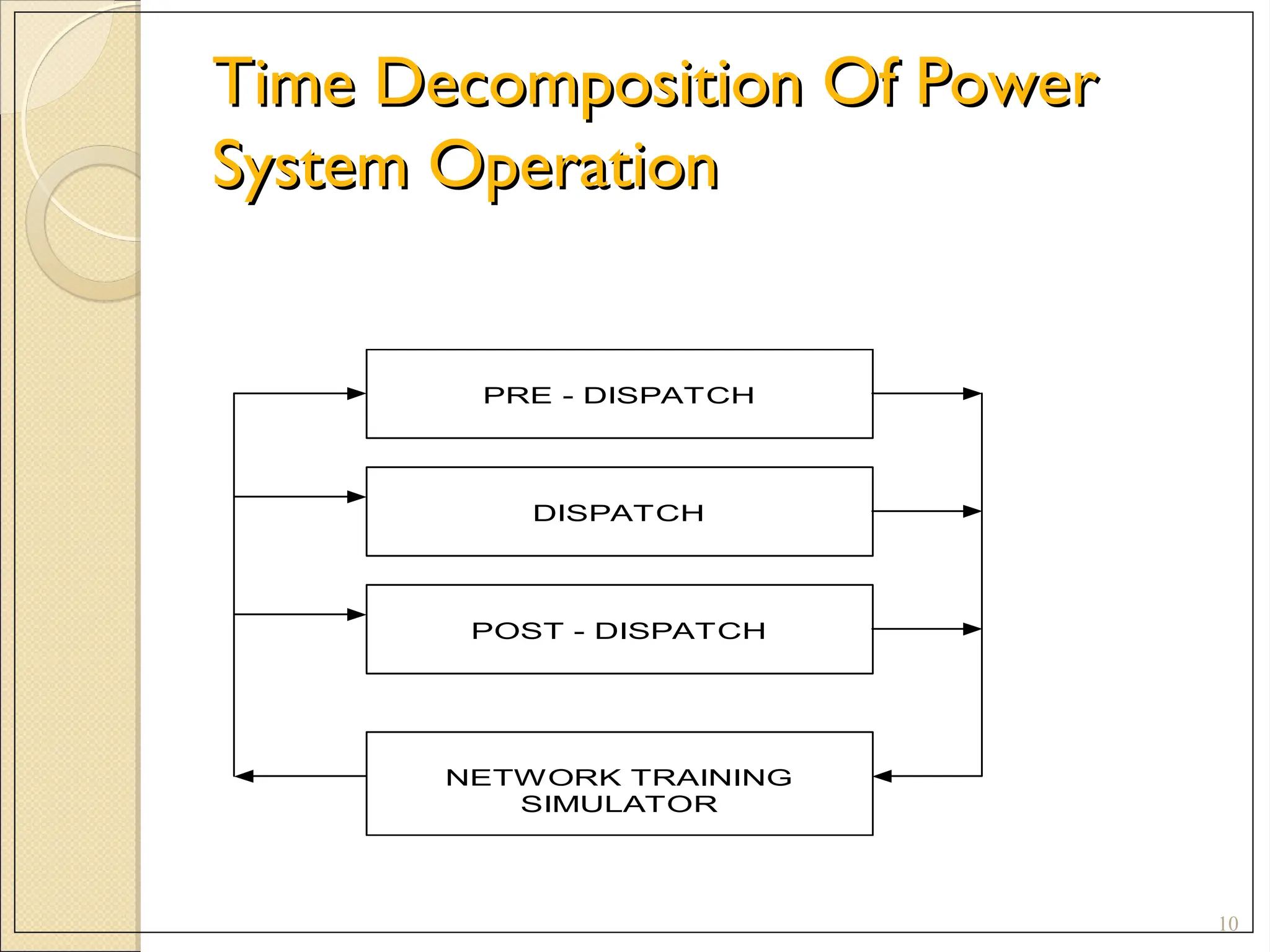
Time Decomposition OfPower
Time Decomposition Of Power
System Operation
System Operation
10
PRE - DISPATCH
DISPATCH
POST - DISPATCH
NETWORK TRAINING
SIMULATOR
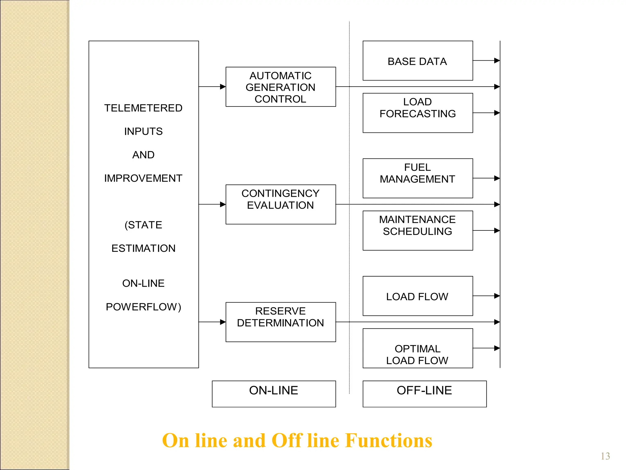
Hierarchical Control inEMS
Hierarchical Control in EMS
12
• Load frequency Control.
• Economic Dispatch.
• Power Exchange with Interconnected utilities.
• Unit commitment.
• Maintenance Scheduling
16
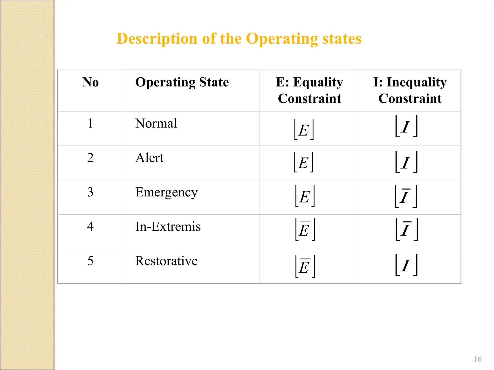
No Operating StateE: Equality
Constraint
I: Inequality
Constraint
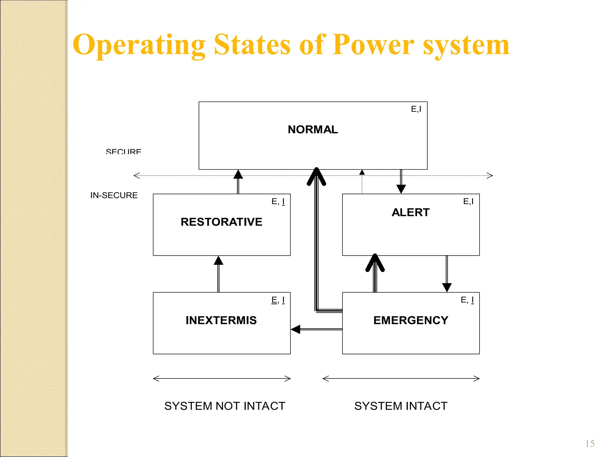
1 Normal
2 Alert
3 Emergency
4 In-Extremis
5 Restorative
E
E
E
E
E
I
I
I
I
I
Description of the Operating states
17.
17
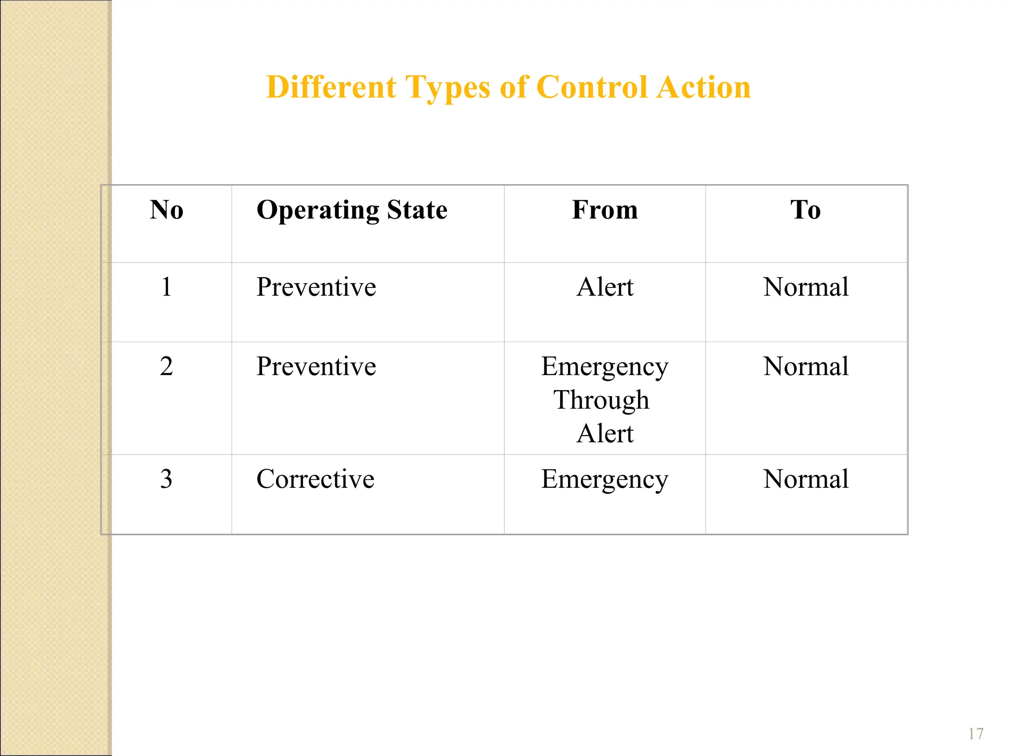
No Operating StateFrom To
1 Preventive Alert Normal
2 Preventive Emergency
Through
Alert
Normal
3 Corrective Emergency Normal
Different Types of Control Action
18.
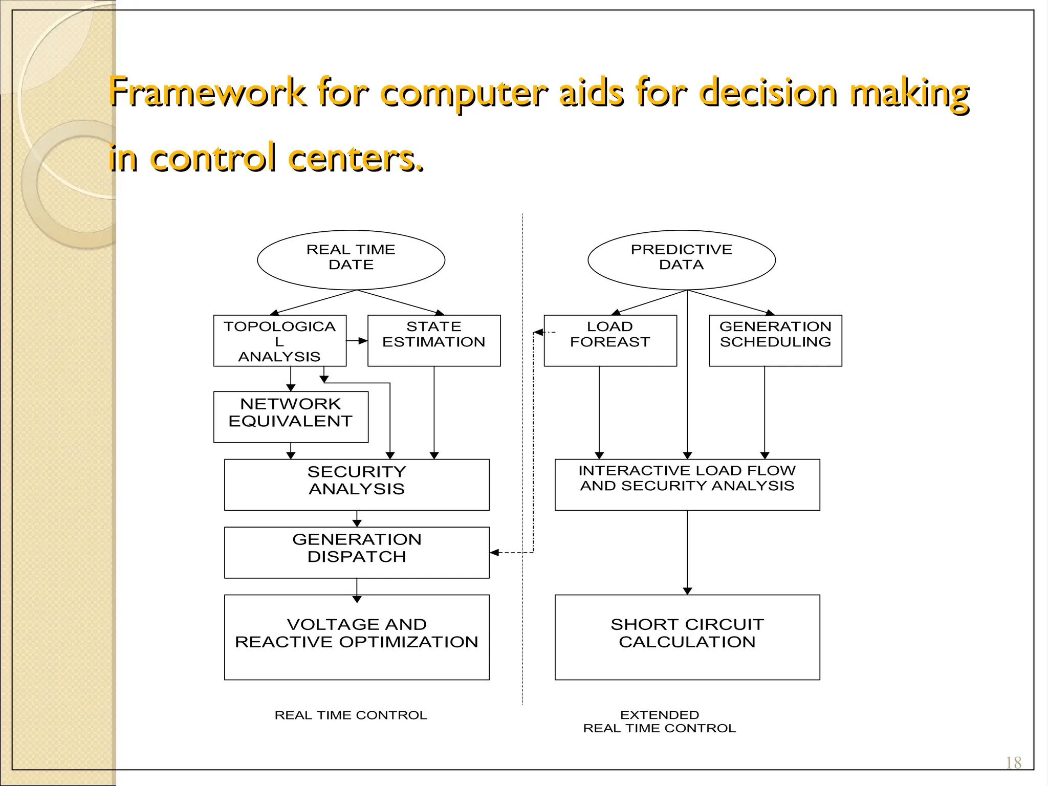
Framework for computeraids for decision making
Framework for computer aids for decision making
in control centers.
in control centers.
18
REAL TIME
DATE
PREDICTIVE
DATA
TOPOLOGICA
L
ANALYSIS
STATE
ESTIMATION
NETWORK
EQUIVALENT
SECURITY
ANALYSIS
GENERATION
DISPATCH
VOLTAGE AND
REACTIVE OPTIMIZATION
LOAD
FOREAST
GENERATION
SCHEDULING
INTERACTIVE LOAD FLOW
AND SECURITY ANALYSIS
SHORT CIRCUIT
CALCULATION
REAL TIME CONTROL EXTENDED
REAL TIME CONTROL
19.
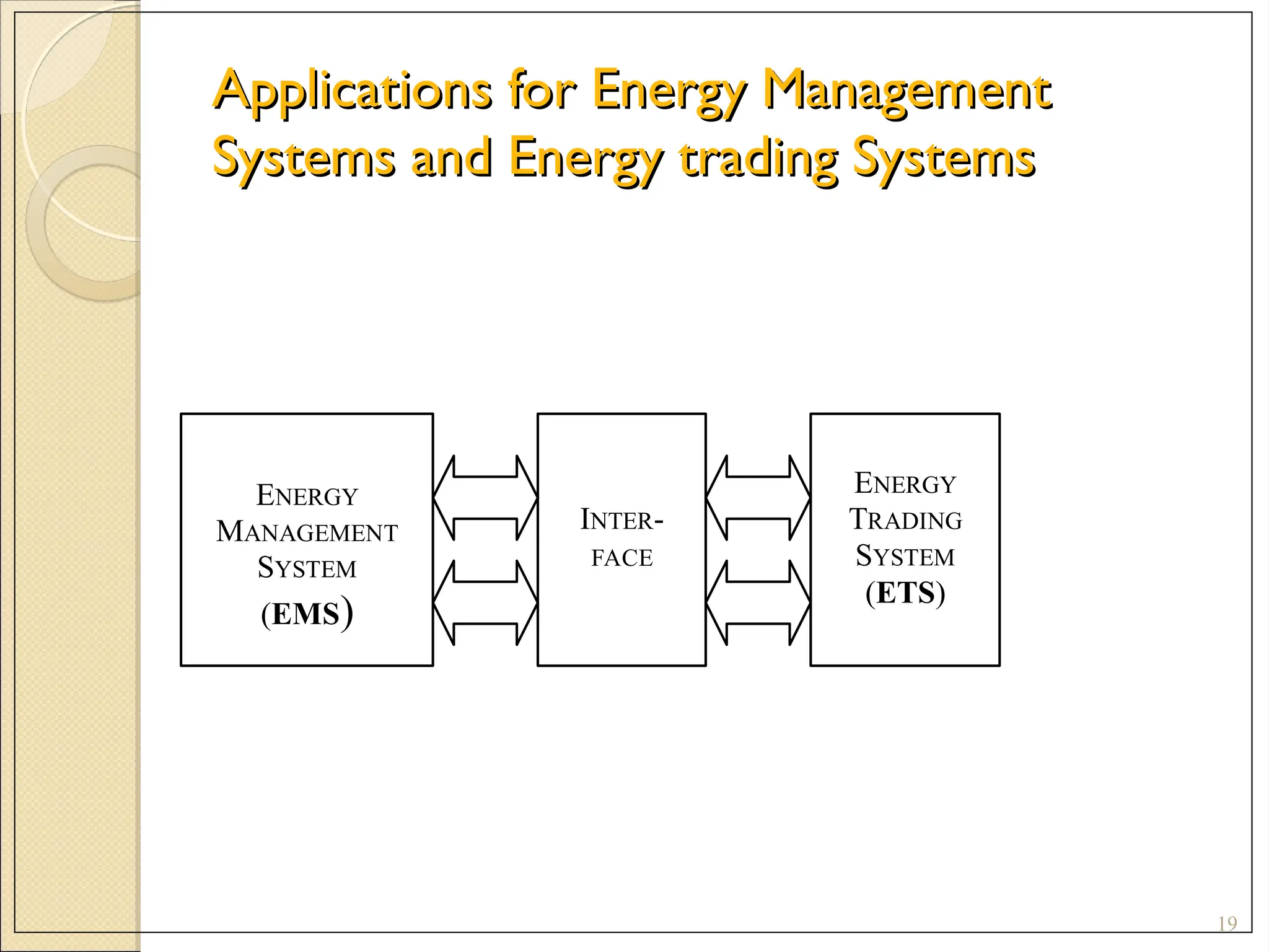
Applications for EnergyManagement
Applications for Energy Management
Systems and Energy trading Systems
Systems and Energy trading Systems
19
INTER-
FACE
ENERGY
TRADING
SYSTEM
(ETS)
ENERGY
MANAGEMENT
SYSTEM
(EMS)
20.
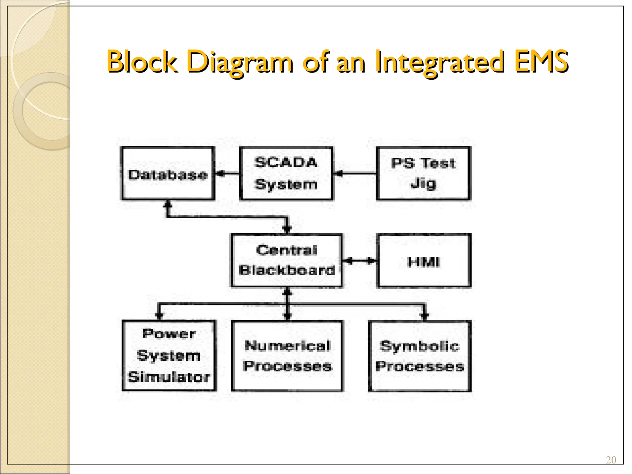
Block Diagram ofan Integrated EMS
Block Diagram of an Integrated EMS
20
21.
21
Open Distributed Systems
ClosedSystem vs. Open System
Closed system software
- Restricted to run on a proprietary platform.
- Data sharing with other computers extremely difficult.
Open System software
No longer relied on the single vendor to supply all the
hardware and software for the EMS
- Select the each individual subsystem within the EMS from
different vendors
22.
Impact of OpenSystems in EMS
Impact of Open Systems in EMS
22
- Purchase the hardware and software requirements for the
sufficient capacity only
- Incrementally upgrade the system as and when required.
- This helps in reducing the financial burden on the utilities
to change from the closed system to the open system.
24
Electric power generation,transmission and distribution:
Electric utilities detect current flow and line voltage, to
monitor the operation of circuit breakers, and to take sections
of the power grid online or offline.
Manufacturing: manage parts inventories for just-in-time
manufacturing, regulate industrial automation and robots,
and monitor process and quality control.
Mass transit: regulate electricity to subways, trams and
trolley buses; to automate traffic signals for rail systems; to
track and locate trains and buses; and to control railroad
crossing gates.
Water and sewage: State and municipal water utilities
use SCADA to monitor and regulate water flow, reservoir
levels, pipe pressure and other factors
25.
Buildings, facilities andenvironments:
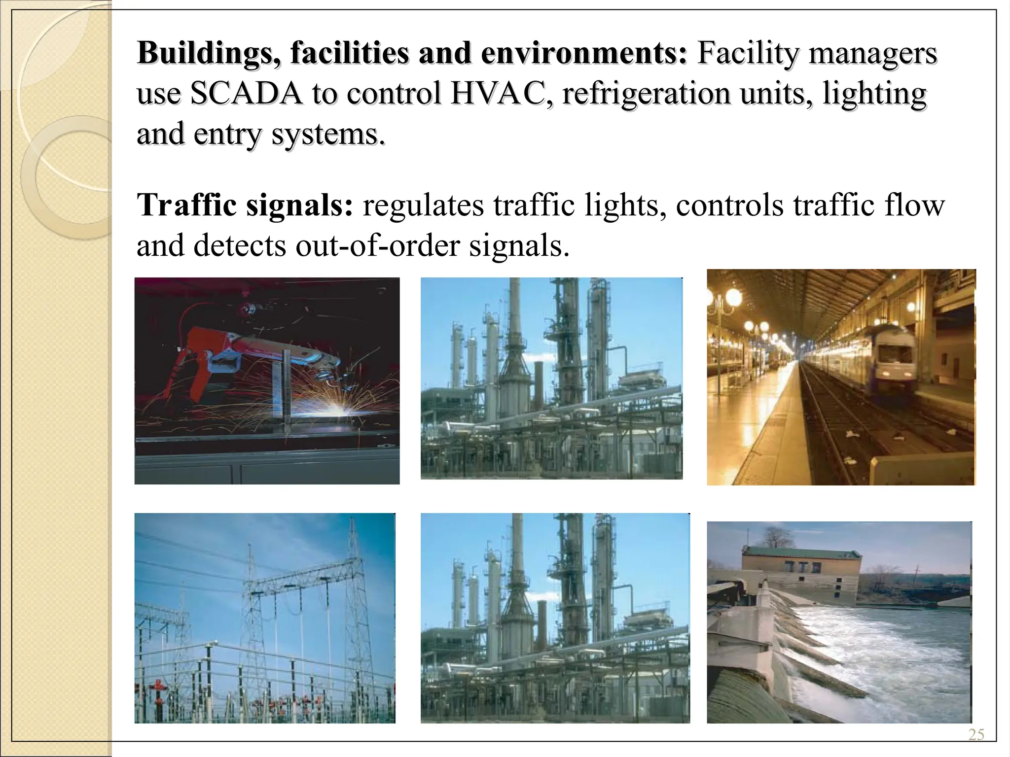
Buildings, facilities and environments: Facility managers
Facility managers
use SCADA to control HVAC, refrigeration units, lighting
use SCADA to control HVAC, refrigeration units, lighting
and entry systems.
and entry systems.
25
Traffic signals: regulates traffic lights, controls traffic flow
and detects out-of-order signals.
26.
26
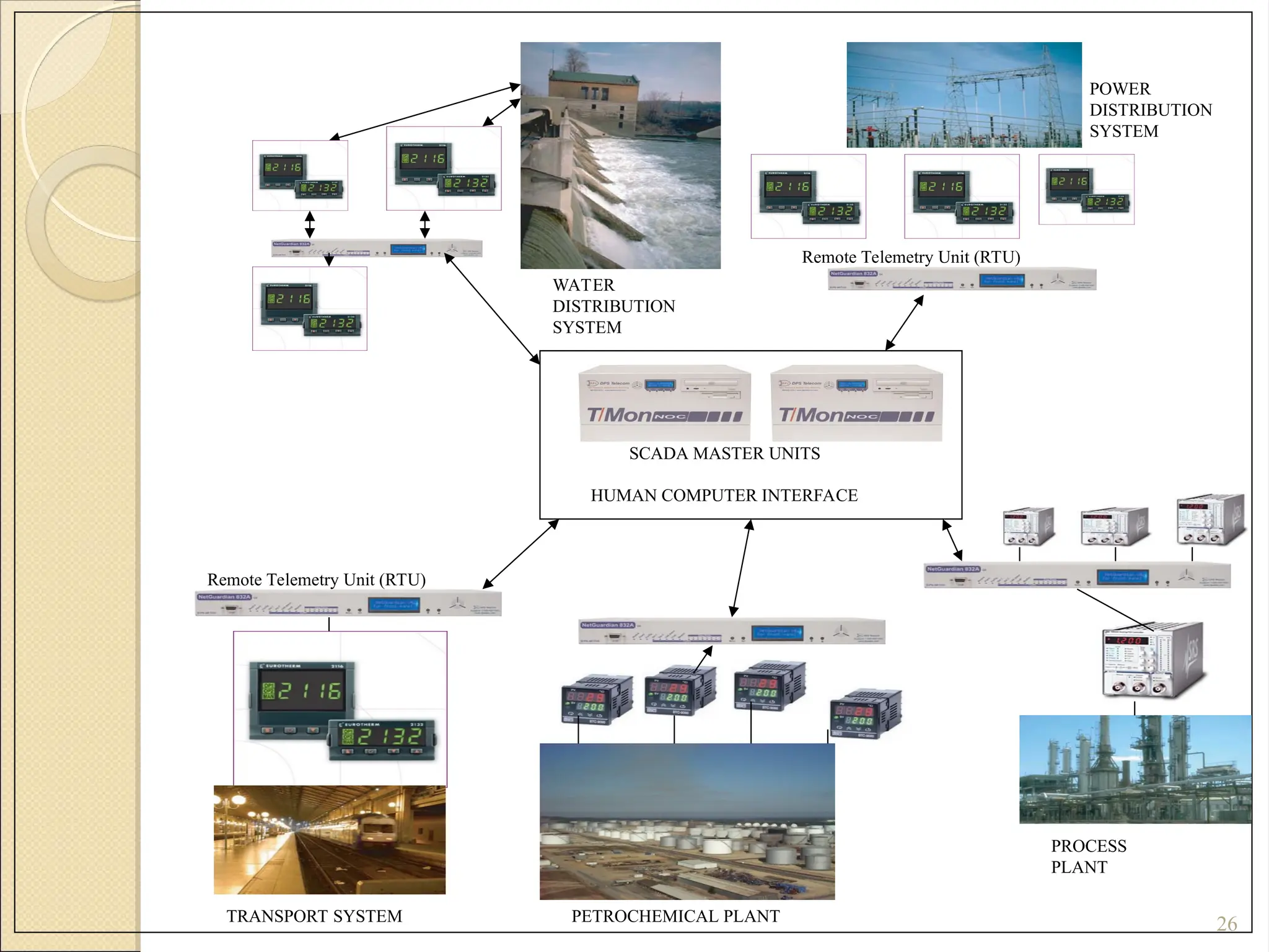
TRANSPORT SYSTEM
Remote TelemetryUnit (RTU)
Remote Telemetry Unit (RTU)
SCADA MASTER UNITS
HUMAN COMPUTER INTERFACE
POWER
DISTRIBUTION
SYSTEM
WATER
DISTRIBUTION
SYSTEM
PROCESS
PLANT
PETROCHEMICAL PLANT
27.
27
A SCADA systemperforms four functions:
1. Data acquisition
2. Networked data communication
3. Data presentation
4. Control
These functions are performed by four kinds of SCADA components:
1. Sensors (either digital or analogue) and control relays that directly
interface with the managed system.
2. Remote telemetry units (RTUs). These are small computerized units
deployed in the field at specific sites and locations. RTUs serve as
local collection points for gathering reports from sensors and
delivering commands to control relays.
3. SCADA master units. These are larger computer consoles that serve as
the central processor for the SCADA system. Master units provide a
human interface to the system and automatically regulate the managed
system in response to sensor inputs.
4. The communications network that connects the SCADA master unit to
the RTUs in the field.
28.
28
Data Acquisition
• SCADAsystem needs to monitor hundreds or thousands of sensors.
Sensors measure:
1. Inputs and outputs e.g. water flowing into a reservoir (input), valve pressure as
water is released from the reservoir (output).
2. Discrete inputs (or digital input) e.g. whether equipment is on or off, or
tripwire alarms, like a power failure at a critical facility.
3. Analogue inputs: where exact measurement is important e.g. to detect
continuous changes in a voltage or current input, to track fluid levels in tanks,
voltage levels in batteries, temperature and other factors that can be measured
in a continuous range of input.
• For most analogue factors, there is a normal range defined by a bottom and top
level e.g. temperature in a server room between 15 and 25 degrees Centigrade.
If the temperature goes outside this range, it will trigger a threshold alarm.
• In more advanced systems, there are four threshold alarms for analogue
sensors, defining Major Under, Minor Under, Minor Over and Major Over
alarms.
29.
29
Data Communication
A communicationsnetwork is required to monitor multiple systems from
a central location.
•TREND: put SCADA data on Ethernet and IP over SONET.
• SECURITY: Keep data on closed LAN/WANs without exposing
sensitive data to the open Internet.
• Encode data in protocol format (use open, standard protocols and
protocol mediation)
• Sensors and control relays can’t generate or interpret protocol
communication - a remote telemetry unit (RTU) is needed to provide an
interface between the sensors and the SCADA network.
• RTU encodes sensor inputs into protocol format and forwards them to
the SCADA master;
• RTU receives control commands in protocol format from the master and
transmits electrical signals to the appropriate control relays.
30.
30
Data Communication
A communicationsnetwork is required to monitor multiple systems from a
central location.
•TREND: put SCADA data on Ethernet and IP over SONET.
• SECURITY: Keep data on closed LAN/WANs without exposing sensitive data
to the open Internet.
• Encode data in protocol format (use open, standard protocols and protocol
mediation)
• Sensors and control relays can’t generate or interpret protocol communication
- a remote telemetry unit (RTU) is needed to provide an interface between the
sensors and the SCADA network.
• RTU encodes sensor inputs into protocol format and forwards them to the
SCADA master;
• RTU receives control commands in protocol format from the master and
transmits electrical signals to the appropriate control relays.
31.
31
Selection of RTU’s
RTUsneed to:
• communicate with all on-site equipment
• survive an industrial environment. Rugged construction and
ability to withstand extremes of temperature and humidity
(it needs to be the most reliable element in your facility).
• have sufficient capacity to support the equipment at a site
(though should support expected growth over a reasonable
period of time).
• have a secure, redundant power supply for 24/7 working,
support battery power and, ideally, two power inputs.
32.
32
Selection of SCADAMaster
A SCADA master should display information in the
most useful ways to human operators and intelligently
regulate managed systems. It should :
• have flexible, programmable soft controls to respond
to sensor inputs
• allow programming for soft alarms (reports of
complex events that track combinations of sensor inputs
and date/time statements).
• automatically page or email directly to repair
technicians and provide detailed information display in
plain English, with a complete description of what
activity is happening and how to manage it.
![4
EMS
- Enhance the scope of SCADA by providing the power
application software to assist the operator in monitoring
and control of the electrical network.
It consists of three important phases:
1. Gathering Information: Acquisition of real-time data
and man machine information.
2. Decision Making.
3. Action by Transmitting Control Orders either
- Directly [Centralized Remote Control]
- Indirectly [Decentralized remote control or load
control].](https://image.slidesharecdn.com/unit-5-ppt1-250528101850-81307a97/75/UNIT-5-PPT-Computer-Control-Power-of-Power-System-4-2048.jpg)