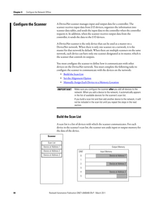
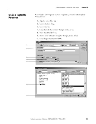
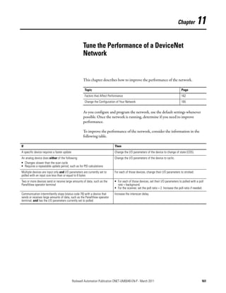
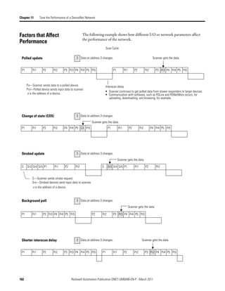
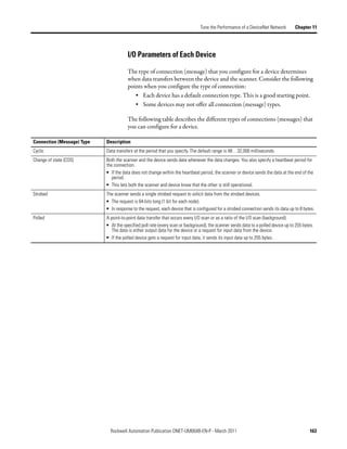
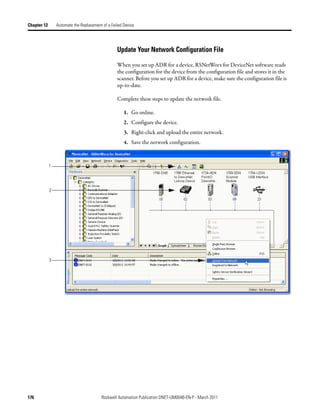
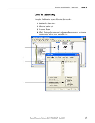
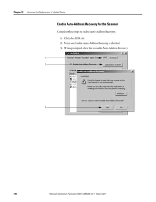
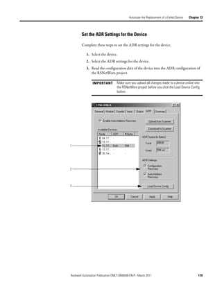
This document provides instructions for configuring a DeviceNet network. It discusses choosing between a single network or subnets, selecting a scanner, and bridging networks. It also covers connecting devices to the network, setting node addresses, and configuring the network both offline and online using RSNetWorx software. A section on automatically configuring the network with AutoScan is also included.


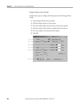
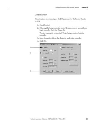
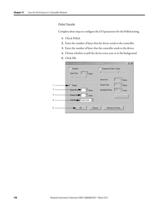
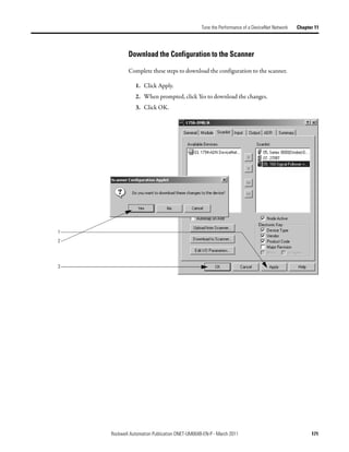
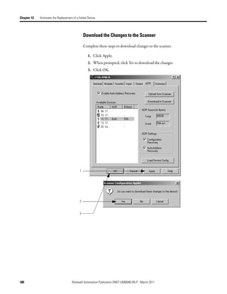
![Configure the Network Offline Chapter 4
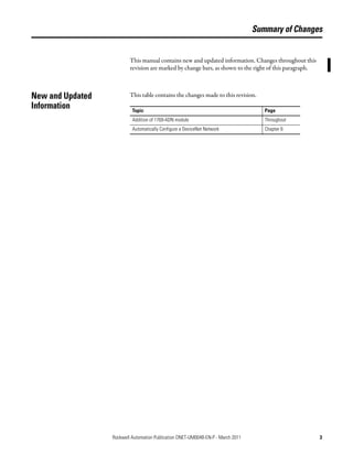
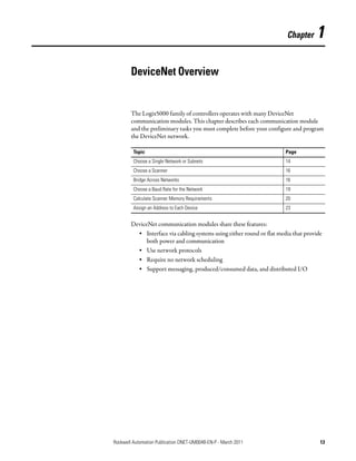
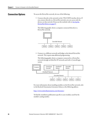
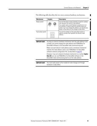
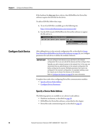
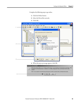
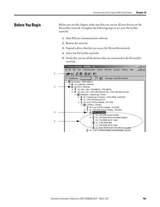
Create Your Network in Before you configure a DeviceNet communication module in RSNetWorx for
DeviceNet software, you must add it to the network configuration file.
RSNetWorx for DeviceNet
Software The finished picture should match the collection of devices that are or will be
physically connected to the DeviceNet network. If the network configuration file
you create offline does not match the physical collection of devices on the
network, you may experience issues when you go online with your project.
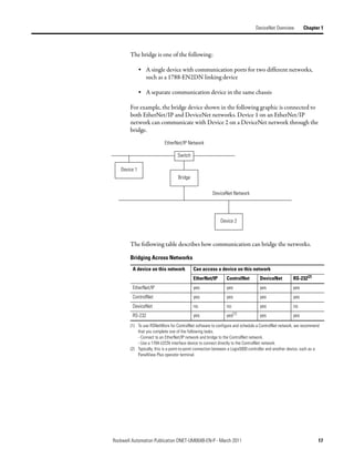
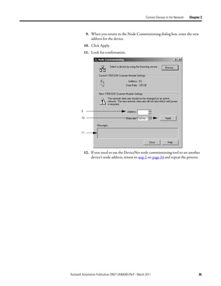
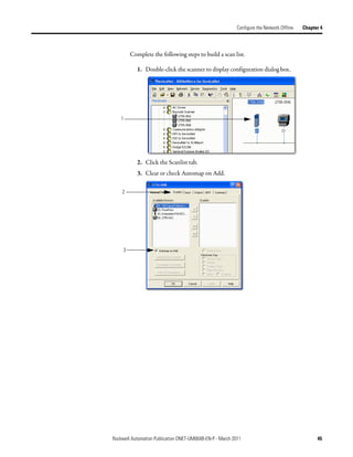
Complete the following steps to add each device to network configuration file.
1. Browse the hardware list for the device.
2. If there is a [+] sign next to the device, click the sign to expand the choices
in that section.
3. Double-click the major revision of the device.
We recommend that the major revision of all devices added to the offline
network match the devices that will be connected to the online network.
4. For a device without a list of major revisions, that is, no [+] or [-] sign,
double-click the device.
1
2
3
4
Rockwell Automation Publication DNET-UM004B-EN-P - March 2011 39](https://image.slidesharecdn.com/devicenetguide-130112111927-phpapp01/85/Device-net-guide-39-320.jpg)
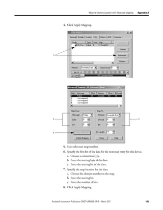
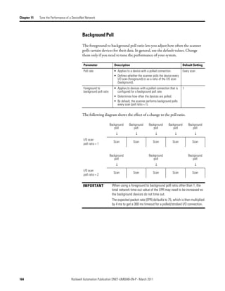
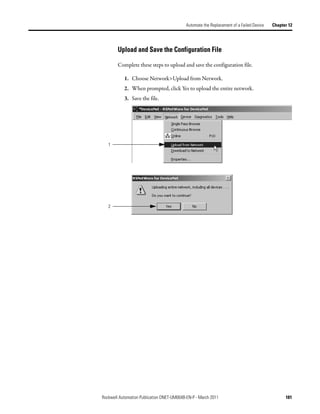
![Chapter 4 Configure the Network Offline
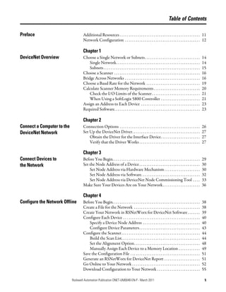
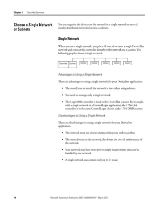
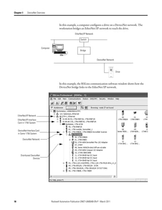
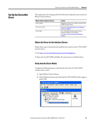
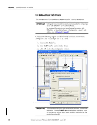
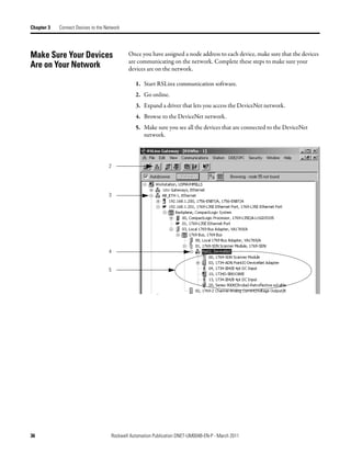
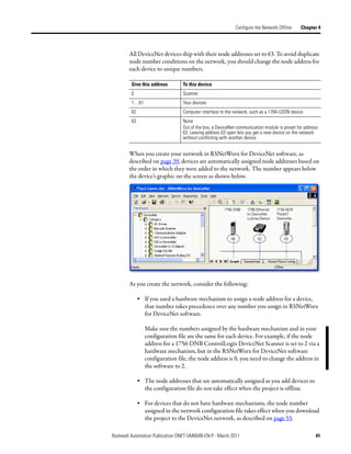
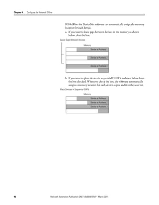
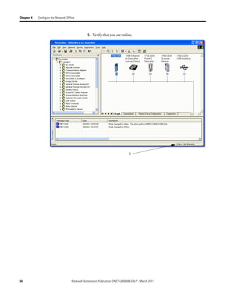
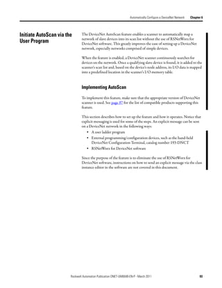
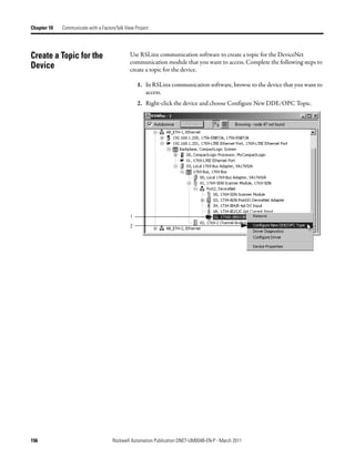
3. In the Start DWord field, enter the element number to which you want to
assign the data.
This is the starting point for the data. Larger data sizes wrap to several
elements. For example, to start the data in . . . Data[3], enter 3 in the Start
DWord box.
4. Click Automap.
An entry for the device appears in the input array.
3
4
5. Click the Output tab and repeat step 2 through step 4.
6. Click OK to complete the scanner configuration.
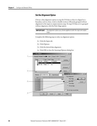
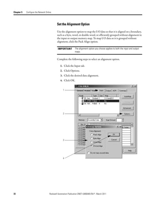
Sometimes, a specific input or output value may end up as the upper bytes of a
DINT in the scanner.
To make your programming easier, use advanced mapping to re-map the value to
its own memory location. For more information, see Map the Memory Location
with Advanced Mapping on page 183.
50 Rockwell Automation Publication DNET-UM004B-EN-P - March 2011](https://image.slidesharecdn.com/devicenetguide-130112111927-phpapp01/85/Device-net-guide-50-320.jpg)
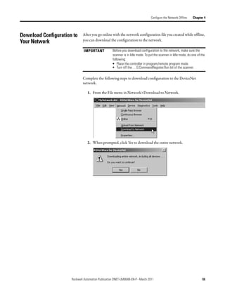

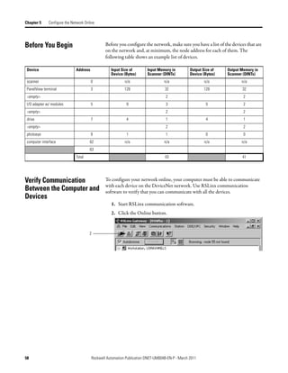


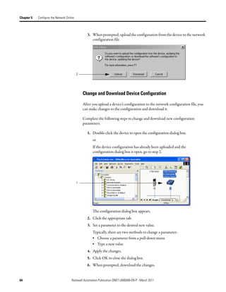
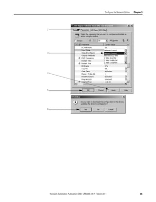
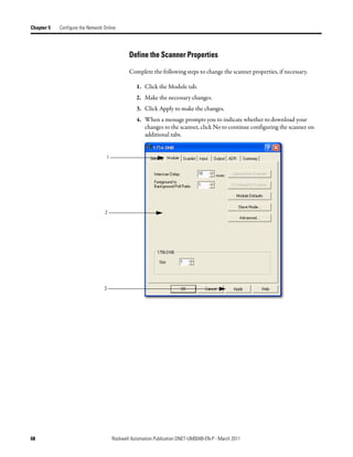
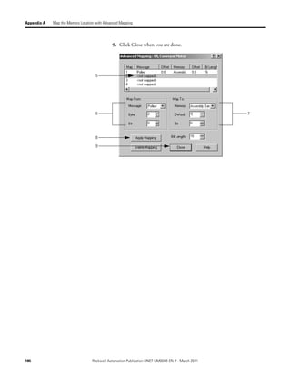
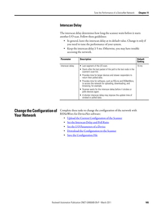
![Chapter 5 Configure the Network Online
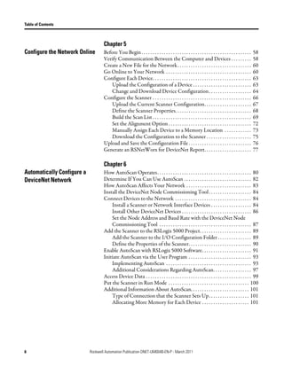
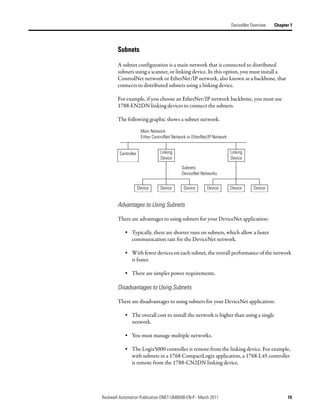
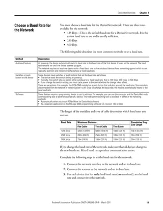
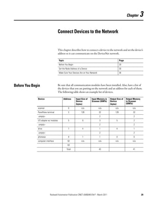
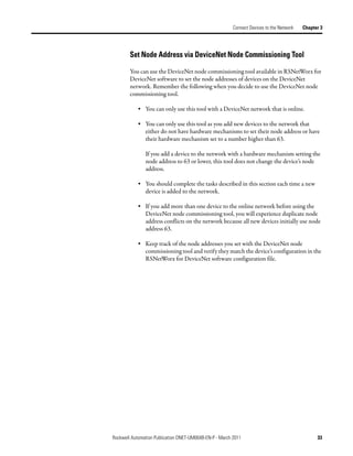
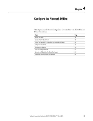
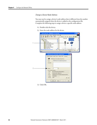
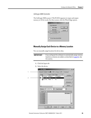
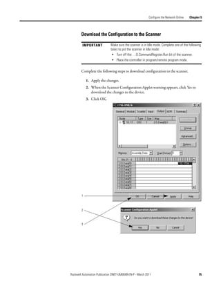
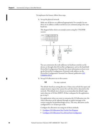
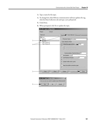
3. In the Start DWord field, enter the element number to which you want to
assign the data.
This is the starting point for the data. Larger data sizes wrap to several
elements. For example, to start the data in . . . Data[3], type 3 in the Start
DWord box.
4. Click Automap.
An entry for the device shows up in the input array.
3
4
5. Click the Output tab and repeat step 2 through step 4.
6. Click OK to complete scanner configuration.
Sometimes, a specific input or output value may end up as the upper bytes of a
DINT in the scanner.
To make your programming easier, use advanced mapping to re-map the value to
its own memory location. For more information, see Map the Memory Location
with Advanced Mapping on page 183.
74 Rockwell Automation Publication DNET-UM004B-EN-P - March 2011](https://image.slidesharecdn.com/devicenetguide-130112111927-phpapp01/85/Device-net-guide-74-320.jpg)


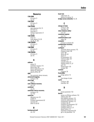
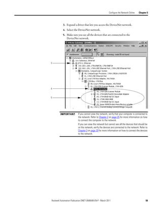
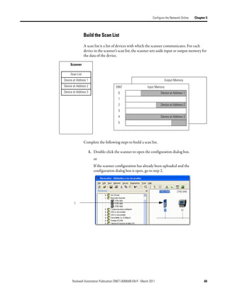
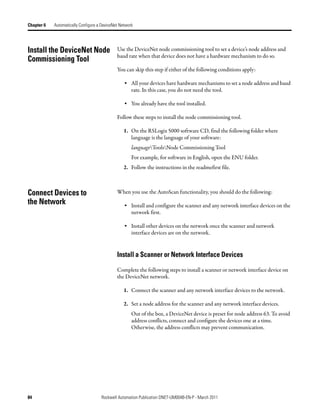
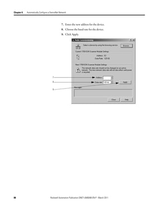
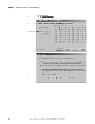
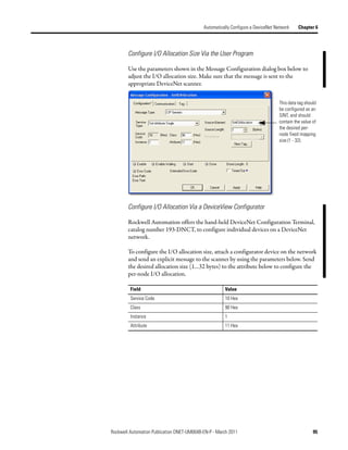
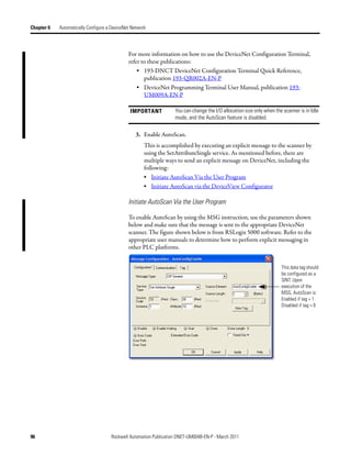
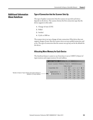
![Automatically Configure a DeviceNet Network Chapter 6
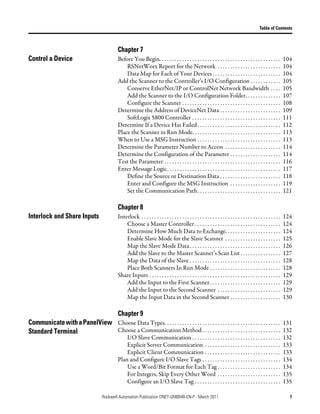
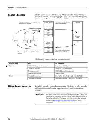
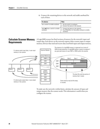
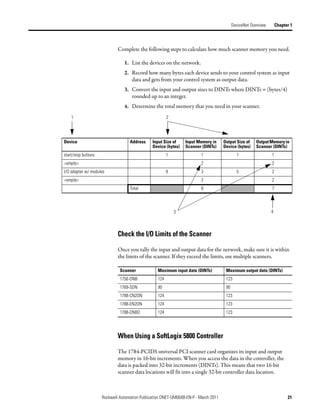
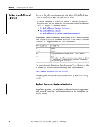
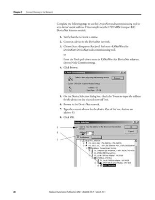
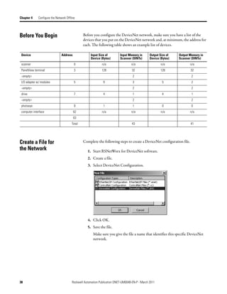
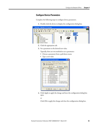
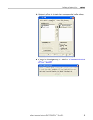
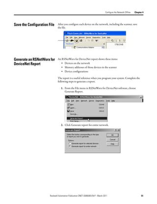
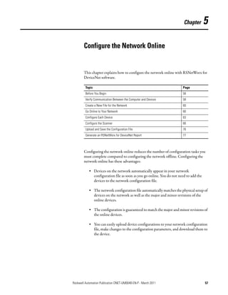
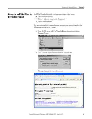
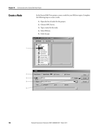
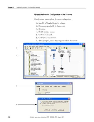
The input and output data is mapped into the scanner's I/O data table based on
the device's node address and the configured fixed mapping size. The DINT-
based formula that is used with the CompactLogix controller for calculating the
input or output data location is as follows:
Input (Output) Offset = [(Node Address) x (Allocation Size)] / 4
EXAMPLE When using the default fixed mapping size of 4 bytes, the input data for the devices shown in the example below is
allocated in the 1769-SDN's input table as shown below. Notice node 1 is in the data map at DINT location 1, node 2
at DINT location 2, and so on.
01 02 03 05
Notice that, in this example, node 4 is unused. However, the I/O memory slot remains allocated for it.
IMPORTANT If you are using a MicroLogix 1500 controller with a 1769-SDN
scanner, you must use the following WORD-based formula for
calculating the input or output data location:
Input (Output) Offset = ([(Node Address) x (Allocation Size)] / 2) + Data
Offset
In this formula the Data Offset = 66 for Input Offset and 2 for Output
Offset.
The data offset value is used to account for scanners that have a fixed status field
at the start of the input or output data, such as the 1769-SDN scanner.
Rockwell Automation Publication DNET-UM004B-EN-P - March 2011 81](https://image.slidesharecdn.com/devicenetguide-130112111927-phpapp01/85/Device-net-guide-81-320.jpg)
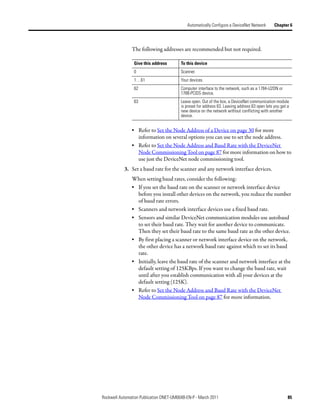
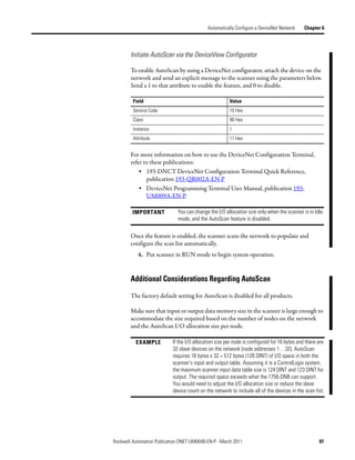
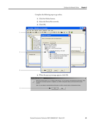
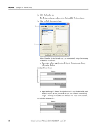
![Automatically Configure a DeviceNet Network Chapter 6
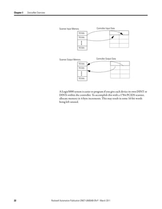
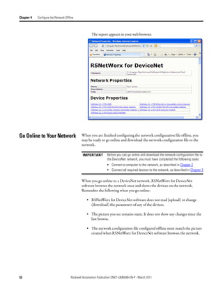
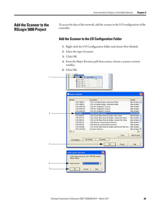
Access Device Data When you add the scanner to the I/O configuration of the controller,
RSLogix 5000 software automatically creates a set of tags for the input, output,
and status data of the network.
Input data from the scanner
Output data for the scanner
Status data from the scanner
The tags for your DeviceNet data follow this format.
location :type .Data [dnet_address] .bit
= Optional
Where Is
location location of the scanner in the system
If you have this scanner In a Then location is
ControlLogix 1756-DNB local chassis Local:slot_number_of_scanner
remote chassis adapter:slot_number_of_scanner
where:
adapter is the name of the EtherNet/IP or ControlNet module in the
remote chassis.
type type of data:
Where Is
input from a device I
output to a device O
dnet_address address of the device on the DeviceNet network (based on only 4 bytes per node)
bit specific bit within the data of the device
While you can use the input and output tags of the scanner directly in your logic,
it is a lot easier to use alias tags. Alias tags can be used whether you use AutoScan
or not to configure the scanner.
Rockwell Automation Publication DNET-UM004B-EN-P - March 2011 99](https://image.slidesharecdn.com/devicenetguide-130112111927-phpapp01/85/Device-net-guide-99-320.jpg)
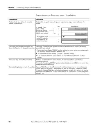
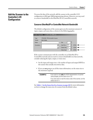
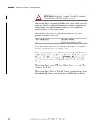
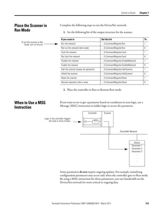
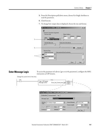
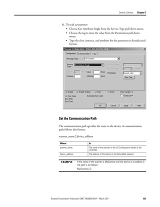
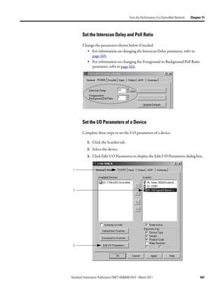
![Chapter 7 Control a Device
Table 1 - Set the Status Size for a Scanner
If you want the following information Set the status This setting gives you the following
size (DINTs) to parameter values.
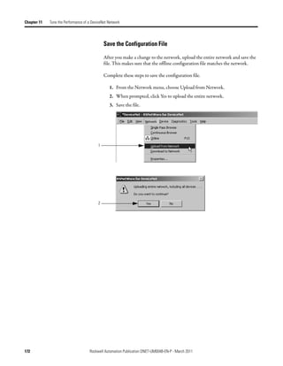
the following
value Member Data Type
Count of I/O scans 10 ScanCounter DINT
Indication that a device has failed: DeviceFailureRegister SINT[8]
• There is 1 bit for each address on the DeviceNet network (0 - 63).
• The position of a bit = address of a device.
• If a bit = 1, then the device at that address has failed.
Indication that the data size of a device does not match the amount of memory AutoverifyFailureRegister SINT[8]
allocated for the device in the scanner:
• There is 1 bit for each address on the DeviceNet network (0 - 63).
• The position of a bit = address of a device.
• If a bit = 1, then their is a mismatch with that address.
Indication that a device is idle: DeviceIdleRegister SINT[8]
• There is 1 bit for each address on the DeviceNet network (0 - 63).
• The position of a bit = address of a device.
• If a bit = 1, then the device at that address is idle.
Indication that a device is online: ActiveNodeRegister SINT[8]
• There is 1 bit for each address on the DeviceNet network (0 - 63).
• The position of a bit = address of a device.
• If a bit = 1, then the device at that address is online.
ASCII representation of scanner status/display StatusDisplay SINT[4]
Address of the scanner 11 ScannerAddress SINT
Status code of scanner ScannerStatus SINT
Address with an error: ScrollingDeviceAddress SINT
• Scrolls through the addresses with errors
• ScrollingDeviceStatus member shows the status code
Status code of an address with an error: ScrollingDeviceStatus SINT
• Scrolls through addresses with errors
• ScrollingDeviceAddress member shows the address
Possible future expansion of the structure—5 DINTs 16
Status code of lower 32 devices—1 byte per device 24 DeviceStatus SINT[32]
Status code of all devices—1 byte per device 32 DeviceStatus SINT[64]
106 Rockwell Automation Publication DNET-UM004B-EN-P - March 2011](https://image.slidesharecdn.com/devicenetguide-130112111927-phpapp01/85/Device-net-guide-106-320.jpg)
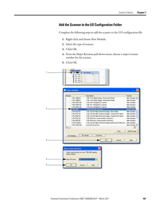
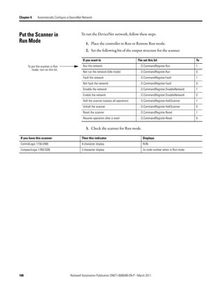
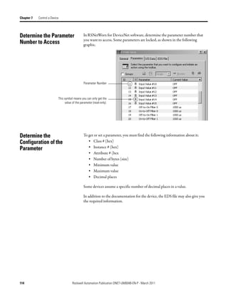
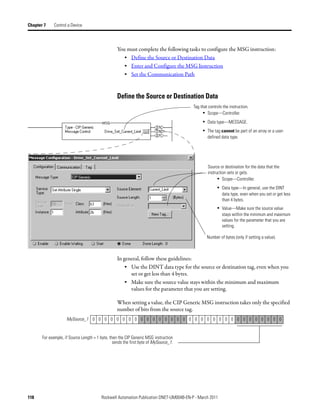
![Control a Device Chapter 7
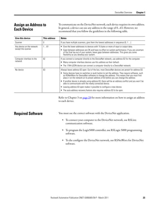
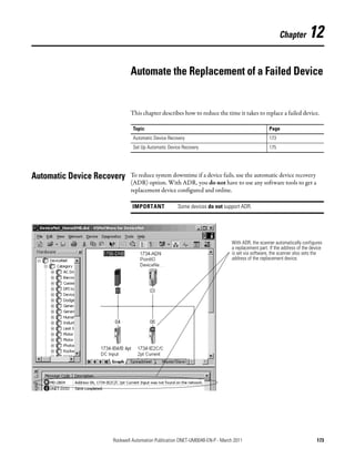
Determine the Address of When you add the scanner to the I/O configuration of the controller,
RSLogix 5000 programming software automatically creates a set of tags for the
DeviceNet Data input, output, and status data of the network.
Input Data from the Scanner
Output Data for the Scanner
Status Data from the Scanner
The tags for your DeviceNet data follow this format.
The scanner memory uses this format... which is this tag in the controller.
slot type .Data [element] .bit location :type .Data [element] .bit
= Optional
Where Is
Slot The slot number of the scanner
Location If you have this scanner Then location is
Local ControlLogix 1756-DNB Local:slot_number_of_scanner
Remote ControlLogix 1756-DNB name_of_remote_bridge:slot_number_of_scanner
CompactLogix 1769-SDN Local:slot_number_of_scanner
SoftLogix 5800 1784-PCIDS Local:slot_number_of_scanner
Linking Device 1788-EN2DN or 1788- The name of the linking device in the I/O configuration of the controller
CN2DN
Type If the data is Then type is
Input from a device I
Output to a device O
The status of the network S
Element A specific DINT (DWord, 32-bit integer) within the array
Bit A specific bit within an integer
Rockwell Automation Publication DNET-UM004B-EN-P - March 2011 109](https://image.slidesharecdn.com/devicenetguide-130112111927-phpapp01/85/Device-net-guide-109-320.jpg)
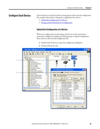
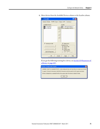
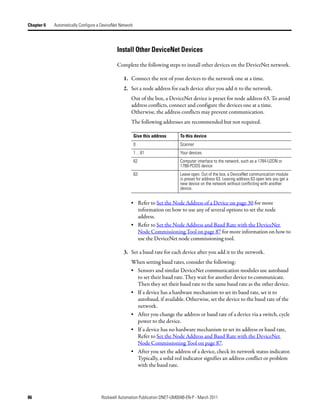
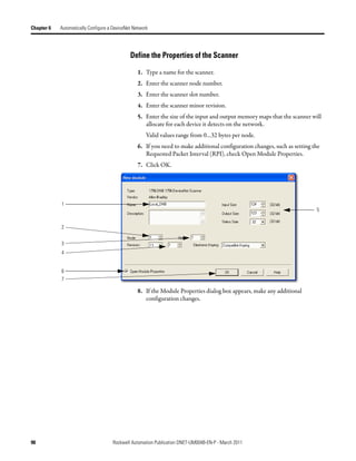
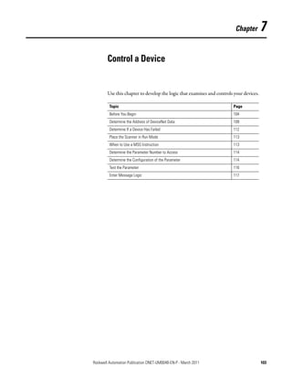
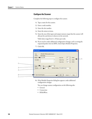
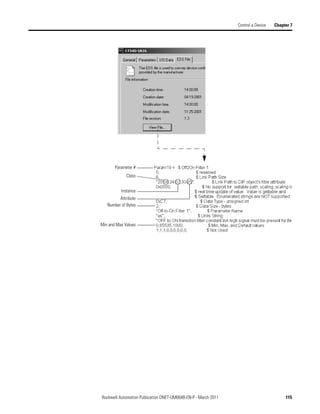
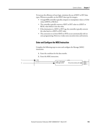
![Chapter 7 Control a Device
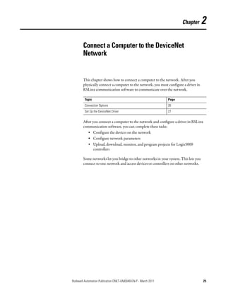
Complete the following steps to determine the tag name, or address, for
DeviceNet data.
1. On the RSNetWorx report for the network, find the memory address for
the input or output data of the device.
2. Find the corresponding tag in the controller-scoped tags of the controller.
3. Find the required data within the controller tag.
Use the data map for the device as a reference.
1
2
3
Local:2:I.Data[0] 0 0 0 0 0 0 0 0 0 0 0 0 0 0 0 0 0 0 0 0 0 0 0 0 0 0 0 0 0 0 0 0
Data Map for
Bulletin 160 AC drive
110 Rockwell Automation Publication DNET-UM004B-EN-P - March 2011](https://image.slidesharecdn.com/devicenetguide-130112111927-phpapp01/85/Device-net-guide-110-320.jpg)

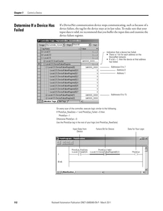
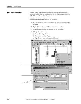
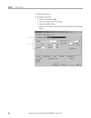
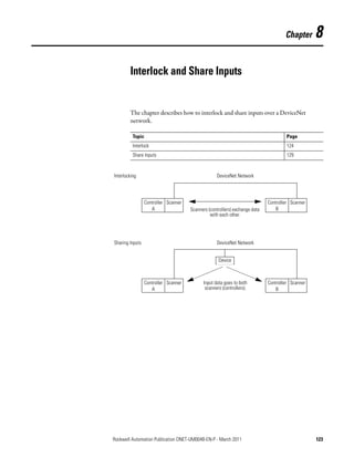
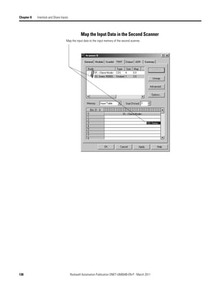
![Chapter 8 Interlock and Share Inputs
Interlock To set up an interlock between two controllers over a DeviceNet network,
complete the following tasks:
• Choose a Master Controller
• Determine How Much Data to Exchange
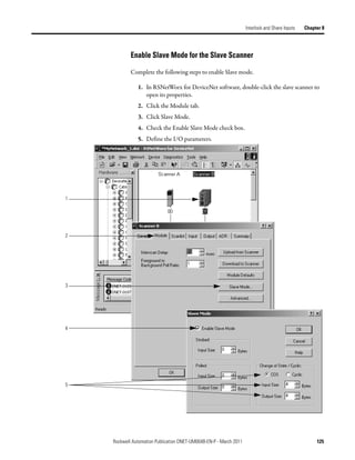
• Enable Slave Mode for the Slave Scanner
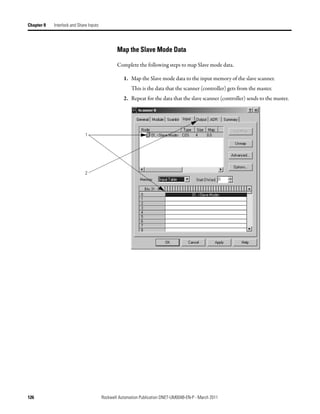
• Map the Slave Mode Data
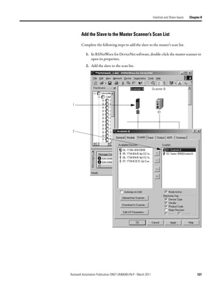
• Add the Slave to the Master Scanner’s Scan List
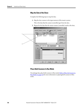
• Map the Data of the Slave
• Place Both Scanners In Run Mode
Choose a Master Controller
To interlock, choose a controller to serve as the master. The other controller
becomes a slave to the master. This defines the relationship between the
controllers. The scanners of each controller still scan and control their own
devices, if desired.
DeviceNet Network
Controller Scanner Controller Scanner
A B
Master Slave
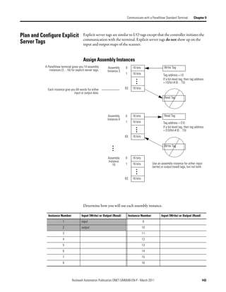
Determine How Much Data to Exchange
Before you configure the scanners for the interlock, determine how much data
you want to exchange between the controllers.
DeviceNet Network
Controller Scanner Controller Scanner
A B
Master Slave
Scanner Input Tag Scanner Input Tag
…I.Data[0] DINT …I.Data[0] DINT
Scanner Output Tag Scanner Output Tag
…O.Data[0] DINT …O.Data[0] DINT
124 Rockwell Automation Publication DNET-UM004B-EN-P - March 2011](https://image.slidesharecdn.com/devicenetguide-130112111927-phpapp01/85/Device-net-guide-124-320.jpg)
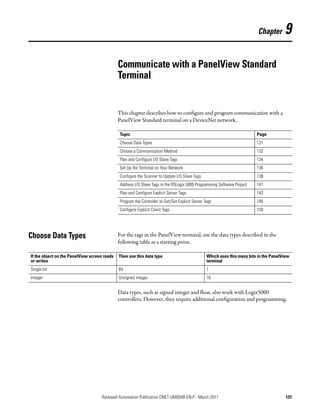
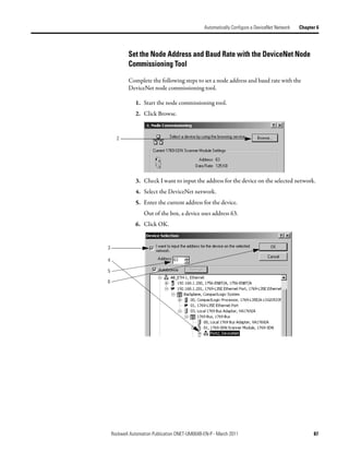
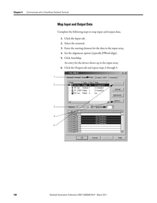
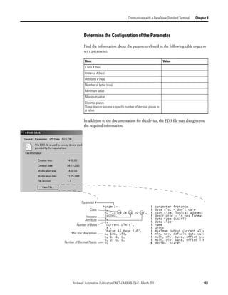
![Chapter 9 Communicate with a PanelView Standard Terminal
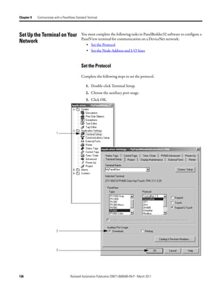
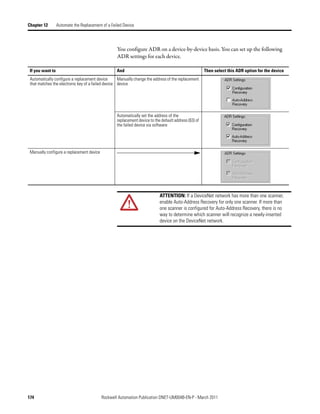
Choose a Communication You have three options to send data to and from a PanelView terminal.
Method
If you want to Use this method Considerations
Communicate with the PanelView terminal using I/O slave • Easiest to use—requires no additional programming.
the regular I/O communication of the DeviceNet • Use this as your first choice.
network • Higher priority on the network than explicit server and
explicit client updates.
Communicate with the PanelView terminal based Explicit server • Provides additional data when you use up the I/O slave
on conditions in your logic assemblies.
• Lower priority on the network than I/O slave updates.
Use the PanelView terminal to get or set a Explicit client • Does not use the controller or scanner.
parameter of a device on your DeviceNet network • Lower priority on the network than I/O slave updates.
(not a controller)
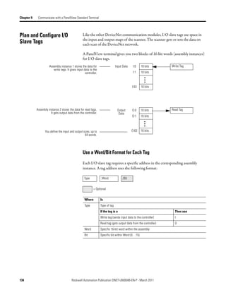
I/O Slave Communication
I/O Slave
Write Tags in PanelView Scanner Input Map
Scanner polls PanelView Terminal for I/O
data. …I.Data[0]
Assembly I:0 16 bits
• You define the input and output sizes up Instance 1
to 64 words. I:1 16 bits
• Assembly instance 1 gives input data to
the controller.
• Assembly instance 2 gets output data
from the controller. I:63 16 bits
Read Tags in PanelView Scanner Output Map
Assembly O:0 16 bits …O.Data[0]
Instance 2
O:1 16 bits
O:63 16 bits
132 Rockwell Automation Publication DNET-UM004B-EN-P - March 2011](https://image.slidesharecdn.com/devicenetguide-130112111927-phpapp01/85/Device-net-guide-132-320.jpg)
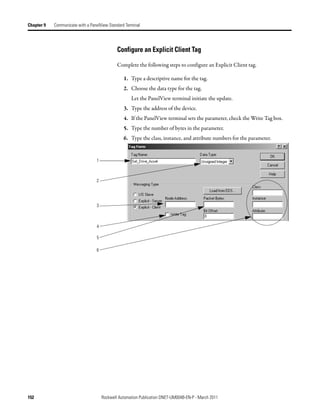
![Communicate with a PanelView Standard Terminal Chapter 9
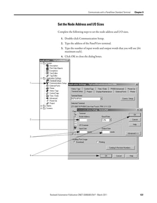
Explicit Server Communication
Explicit Server
Write Tags in PanelView Controller Tags
Controller executes a MSG instruction that
gets or sets data in the PanelView Array_1[0]
Assembly I:0 16 bits
terminal. Instance 3
• 14 assembly instances are I:1 16 bits
available for explicit - server
transfers. MSG
• Instance #s are 3…16. I:63 16 bits CIP Generic
• You define an instance as either
input data (I) or output data (O), but
not both. Read Tags in PanelView Controller Tags
• Each instance provides 64 words Assembly O:0 16 bits Array_2[0]
of either input or output data for Instance 4
the terminal. O:1 16 bits
MSG
O:63 16 bits CIP Generic
Explicit Client Communication
Explicit Client
PanelView Terminal Device
PanelView terminal sets or gets data in
another device on a tag-by-tag basis. Read Tag Parameter
Read Tag Parameter
Write Tag Parameter
Rockwell Automation Publication DNET-UM004B-EN-P - March 2011 133](https://image.slidesharecdn.com/devicenetguide-130112111927-phpapp01/85/Device-net-guide-133-320.jpg)
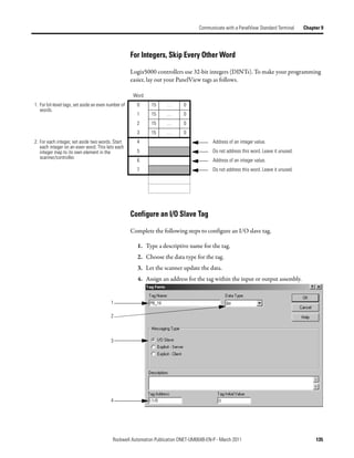
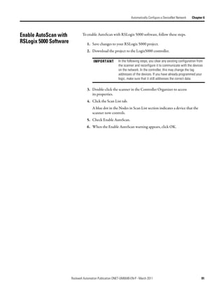
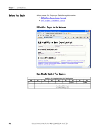
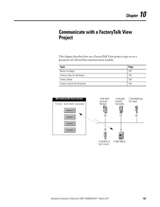
![Communicate with a PanelView Standard Terminal Chapter 9
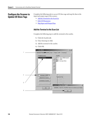
Address I/O Slave Tags in You must get the following information to find the data for an I/O slave tag in
your RSLogix 5000 programming software project:
the RSLogix 5000
• RSNetWorx for DeviceNet report for the network
Programming Software • Address for the tag in the PanelView terminal
Project
Complete the following steps to get the information described previously.
1. On the report for the network, find the memory address for the PanelView
terminal.
2. Find the corresponding tag in the controller-scoped tags of the controller.
3. Find the data within the controller tag.
Use the tag address as a reference.
1
2
3
Local:2:I.Data[10] 0 0 0 0 0 0 0 0 0 0 0 0 0 0 0 0 0 0 0 0 0 0 0 0 0 0 0 0 0 0 0 0
Tag addresses in the I:0 0 0 0 0 0 0 0 0 0 0 0 0 0 0 0 0
PanelView terminal.
I:1 0 0 0 0 0 0 0 0 0 0 0 0 0 0 0 0
Rockwell Automation Publication DNET-UM004B-EN-P - March 2011 141](https://image.slidesharecdn.com/devicenetguide-130112111927-phpapp01/85/Device-net-guide-141-320.jpg)
![Chapter 9 Communicate with a PanelView Standard Terminal
DeviceNet tags use the format described below.
Scanner Memory Format Tag in Controller
slot:type.Data[element].bit location:type.Data[element].bit
Where Is
Location Location of the scanner in the system
If you have this scanner Then location is
ControlLogix 1756-DNB In a Location is
local chassis Local:slot_number_of_scanner
remote chassis adapter:slot_number_of_scanner
where:
adapter is the name of the EtherNet/IP or ControlNet module in
the remote chassis.
CompactLogix 1769-SDN Local:slot_number_of_scanner
SoftLogix 5800 1784-PCIDS
EtherNet/IP to DeviceNet Linking Device The name of the scanner in the I/O configuration of the controller
(1788-EN2DN)
ControlNet to DeviceNet Linking Device
(1788-CN2DN)
Type Type of data:
Where Is
Input from a device I
Output to a device O
Status of the network S
Element A specific DINT (DWord, 32-bit integer) within the array
Bit A specific bit within an integer
SoftLogix 5800 Controller
The SoftLogix 5800 scanner 1784-PCIDS organizes input and output memory
in 16-bit words. It uses the following address format.
word.bit
Where Is
Word INT (16-bit integer) with the memory of the scanner
Bit A specific bit within an integer
142 Rockwell Automation Publication DNET-UM004B-EN-P - March 2011](https://image.slidesharecdn.com/devicenetguide-130112111927-phpapp01/85/Device-net-guide-142-320.jpg)
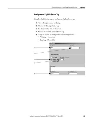
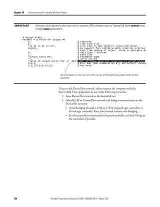
![Chapter 9 Communicate with a PanelView Standard Terminal
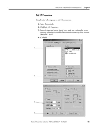
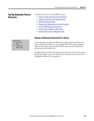
Program the Controller to Complete the following tasks to let the controller read or write data from or to an
Explicit-Server tag:
Get/Set Explicit Server Tags
• Create an Array for the Assembly Instance
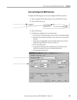
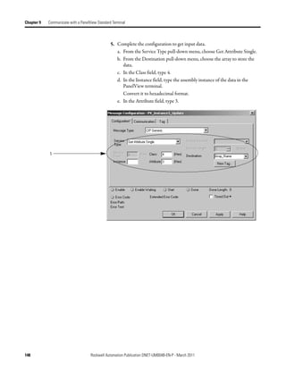
• Enter and Configure the MSG Instruction
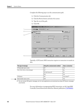
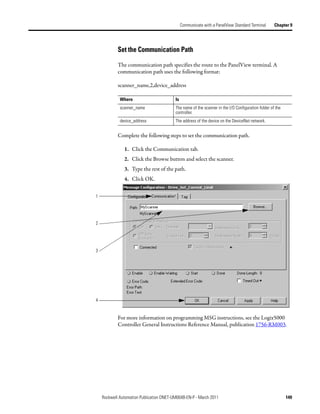
• Set the Communication Path
Create an Array for the Assembly Instance
For each assembly instance that you use for explicit server tags, create an array in
the RSLogix 5000 project for the data.
Write Tags in PanelView Controller Tags
Array_1[0] Data Type = DINT[32]
Assembly I:0 16 bits
Instance 3
I:1 16 bits
Array_1[31]
I:63 16 bits
Read Tags in PanelView Controller Tags
Array_2[0] Data Type = DINT[32]
Assembly O:0 16 bits
Instance 4
O:1 16 bits
Array_2[31]
O:63 16 bits
146 Rockwell Automation Publication DNET-UM004B-EN-P - March 2011](https://image.slidesharecdn.com/devicenetguide-130112111927-phpapp01/85/Device-net-guide-146-320.jpg)


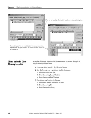
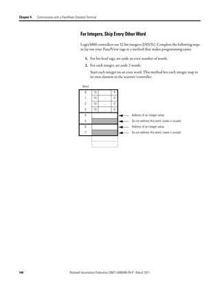
![Appendix A
Map the Memory Location with Advanced
Mapping
Sometimes, an input or output value for a device may end up encapsulated within
a larger tag. For example, a speed value may end up as the upper 16 bits of a
DINT element in the scanner. To access the value, you would have to use
additional programming.
2:I.Data[0] 0 0 0 0 0 0 0 0 0 0 0 0 0 0 0 0 0 0 0 0 0 0 0 0 0 0 0 0 0 0 0 0
Data map for
Bulletin 160
AC drive
To make your programming easier, re-map the value to its own tag within the data
array of the scanner. This lets you access the value without additional
programming.
Rockwell Automation Publication DNET-UM004B-EN-P - March 2011 183](https://image.slidesharecdn.com/devicenetguide-130112111927-phpapp01/85/Device-net-guide-183-320.jpg)