Downloaded 12 times


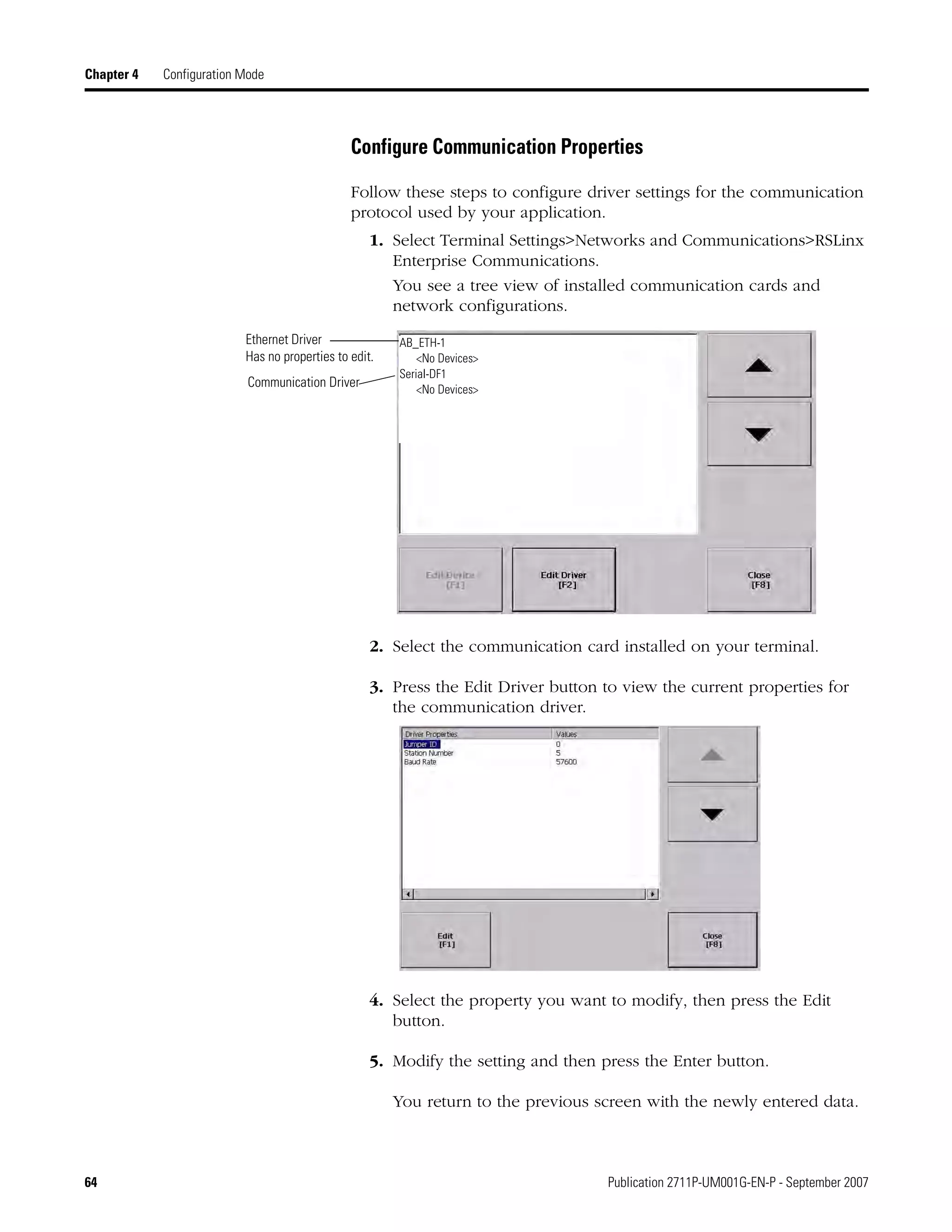
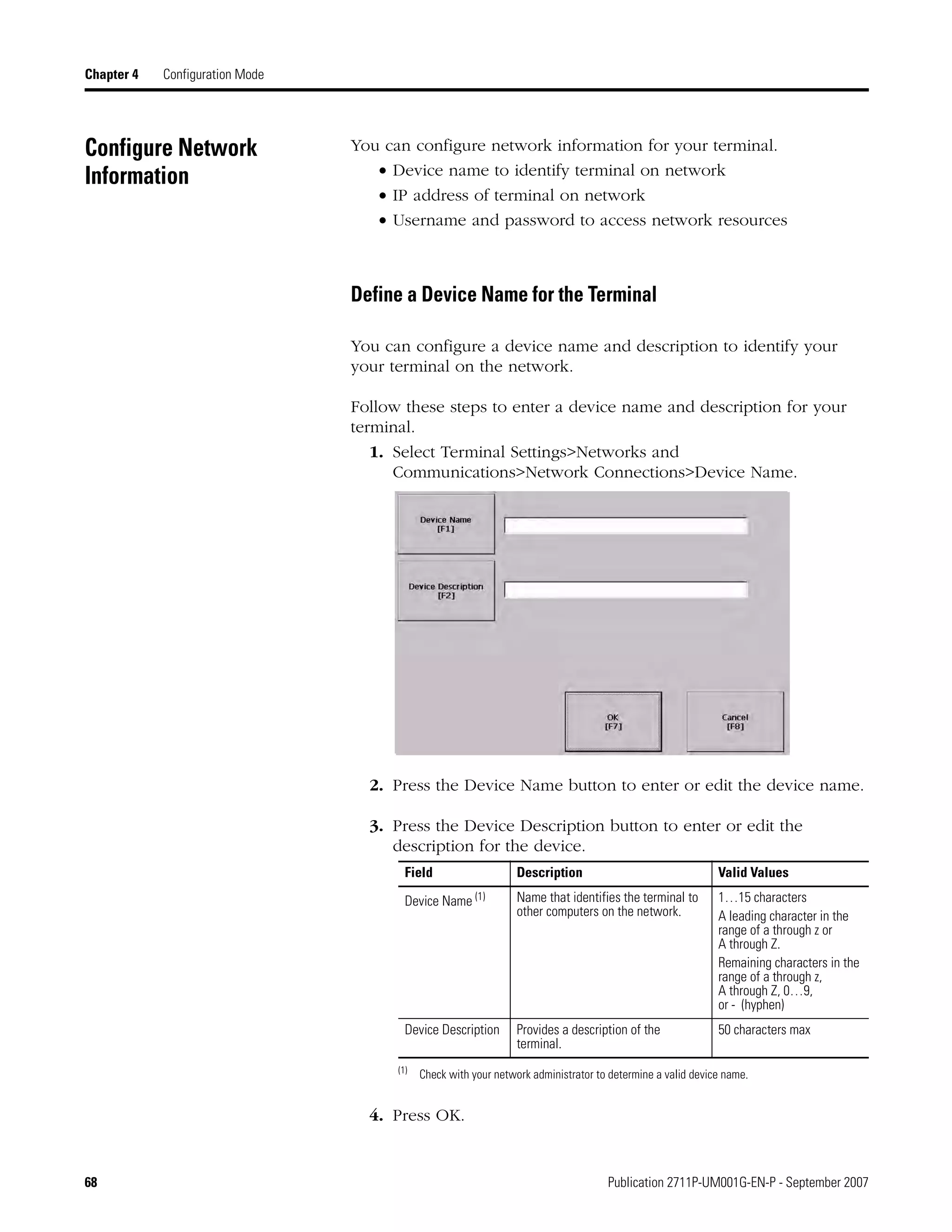
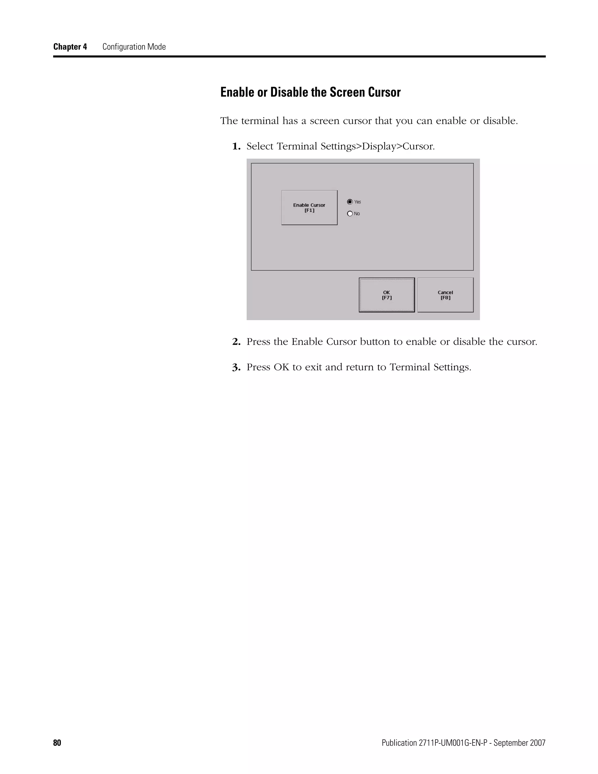
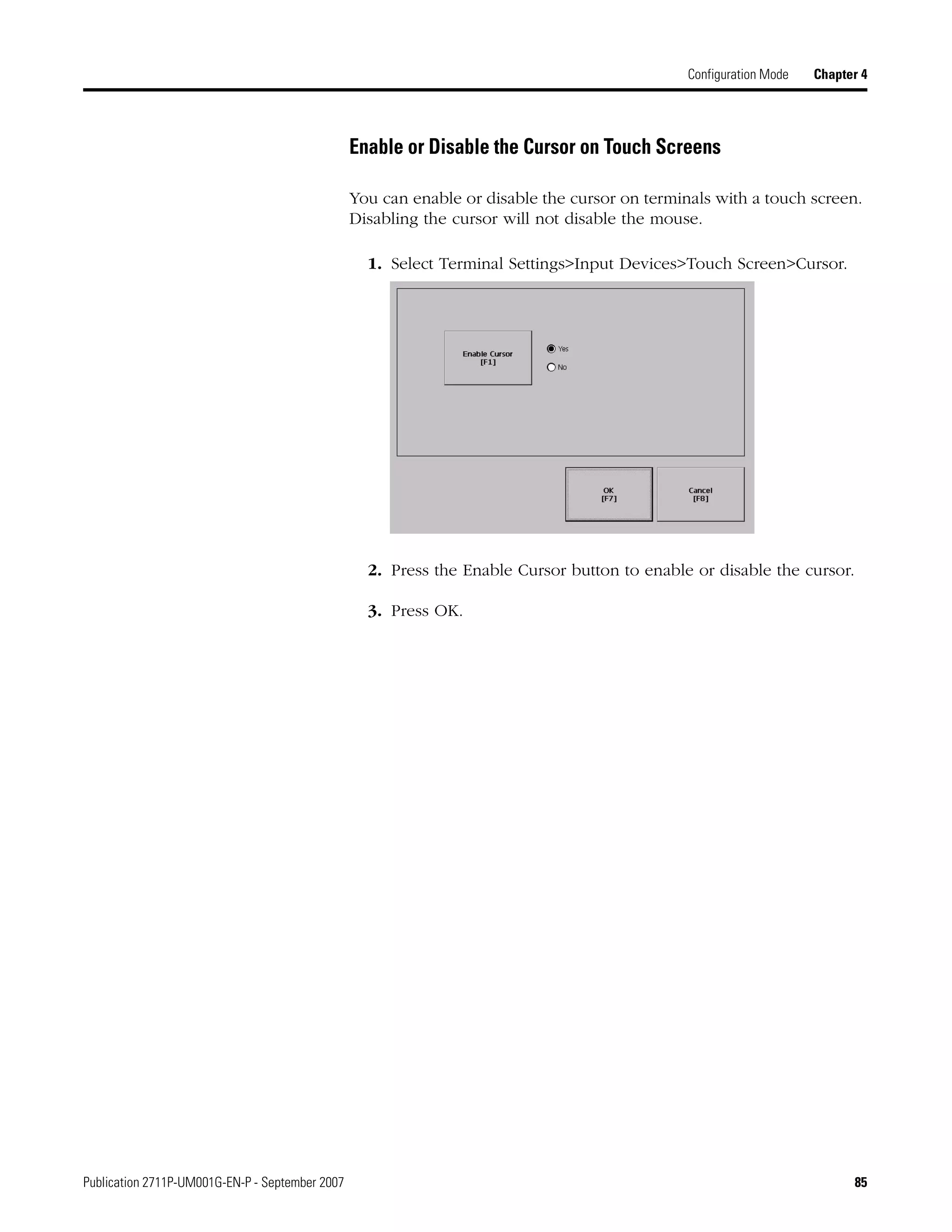
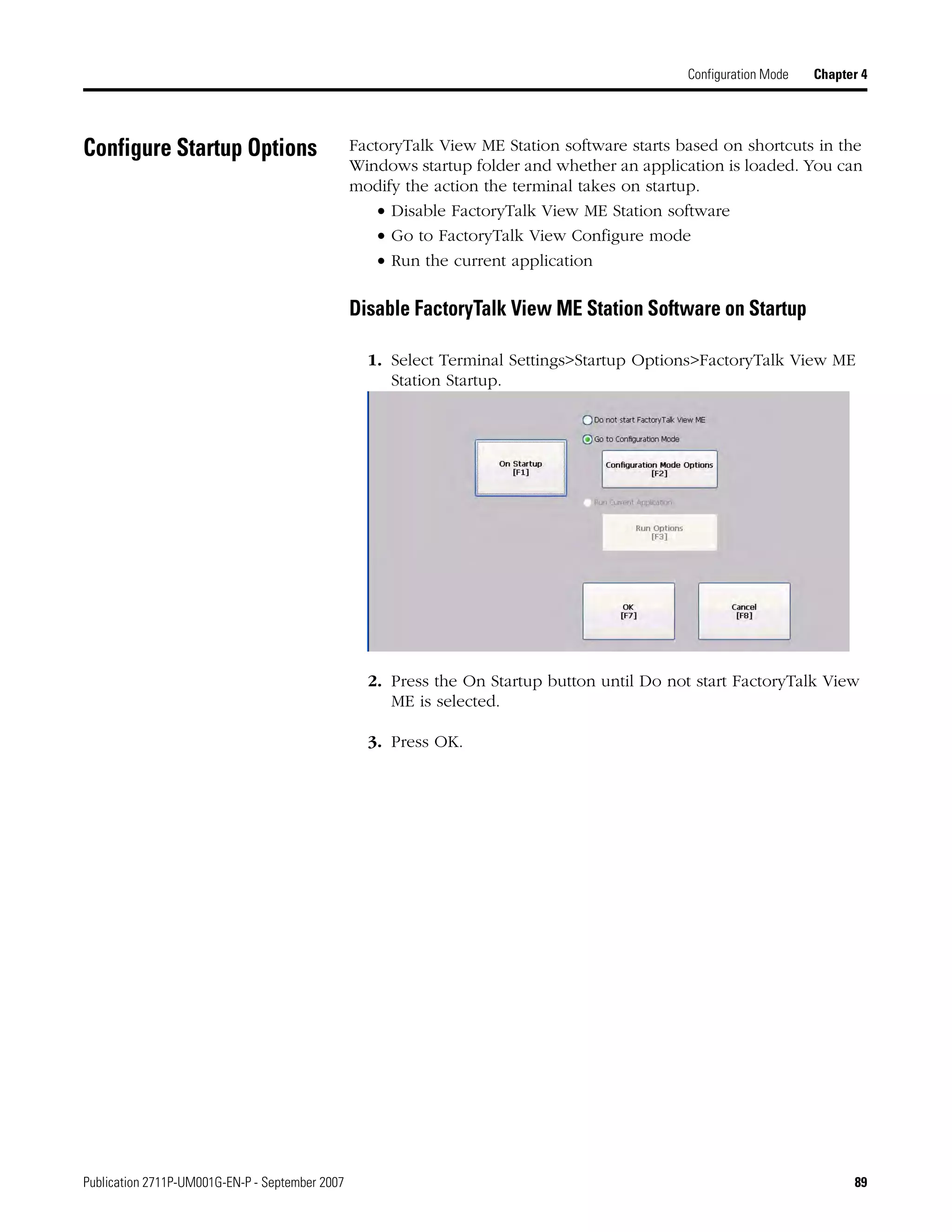
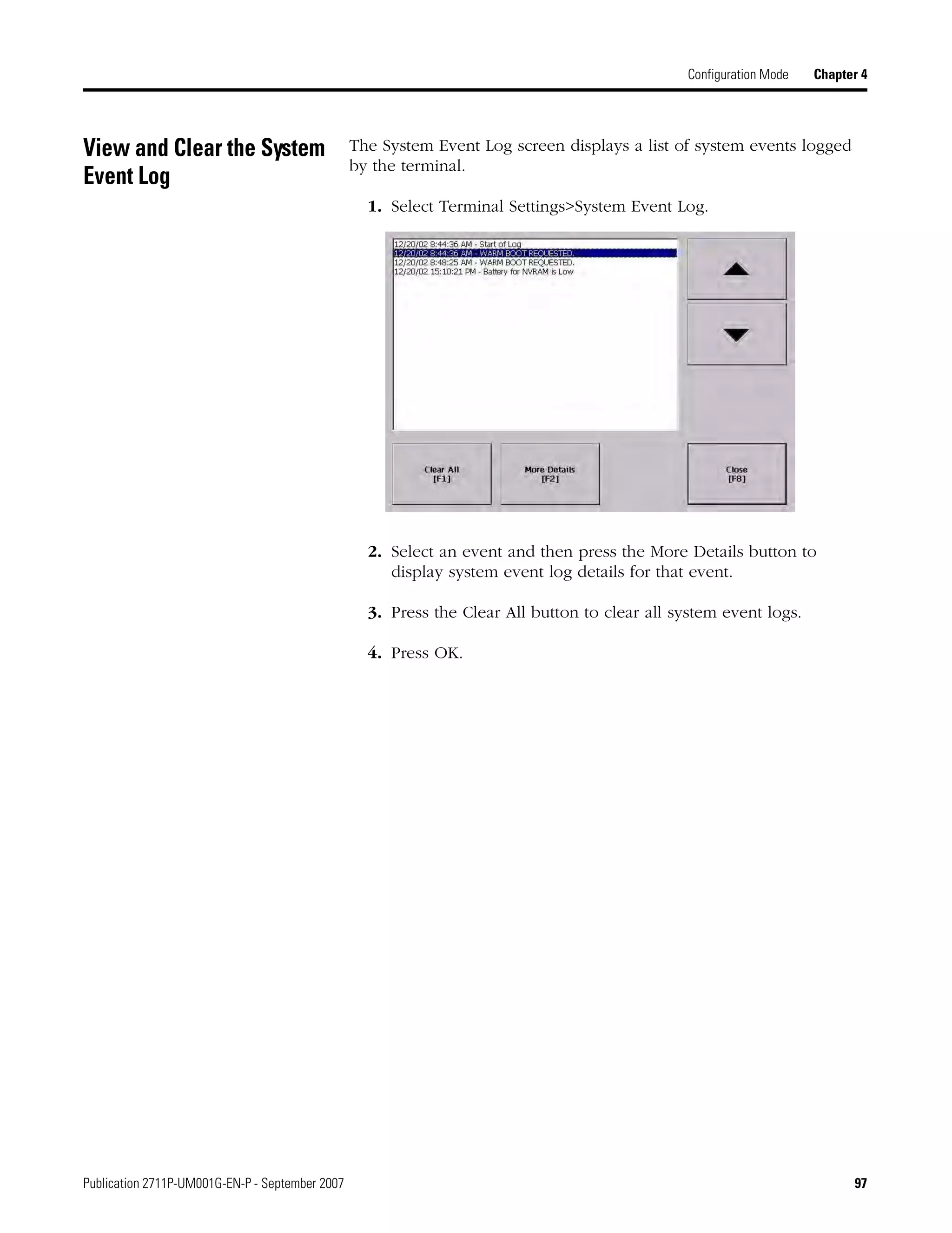
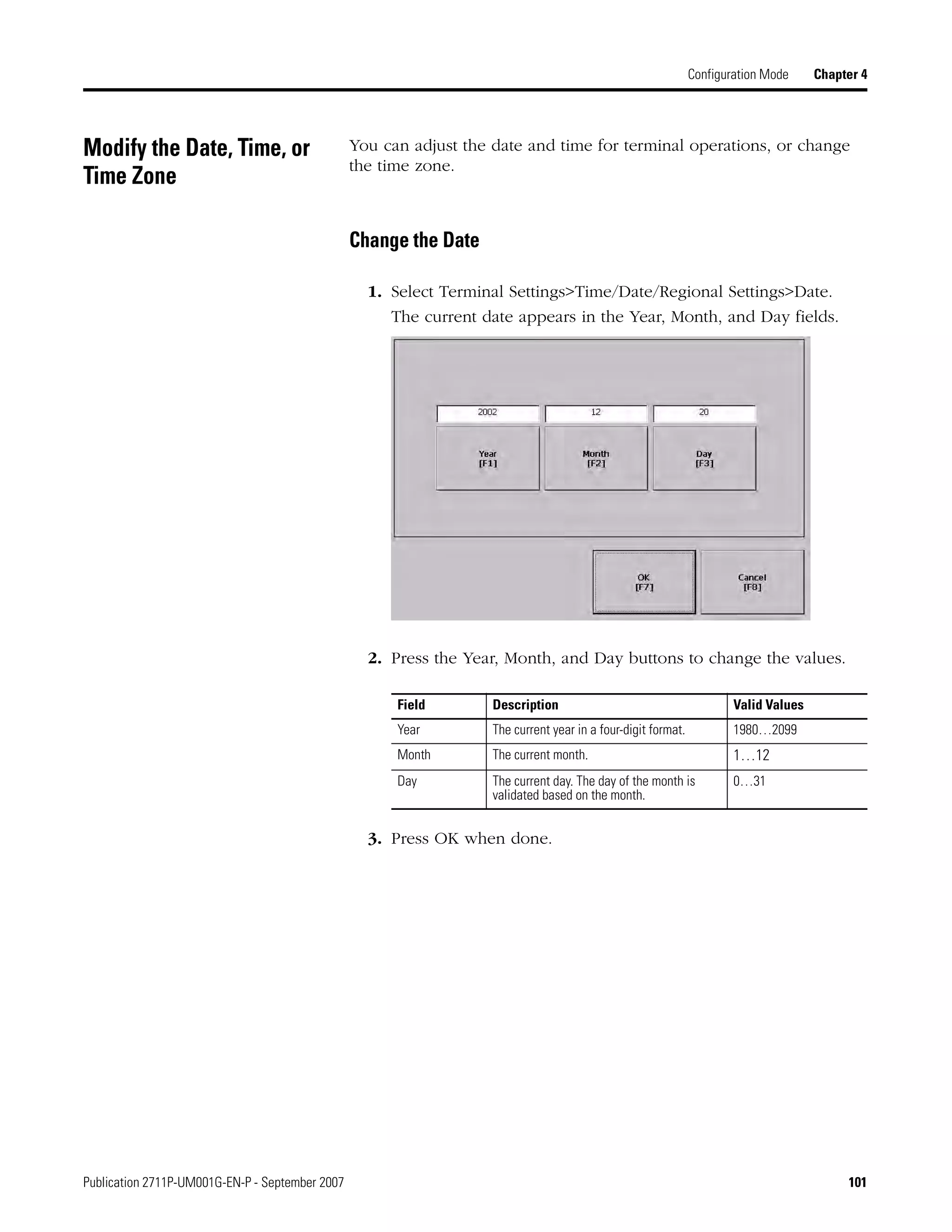
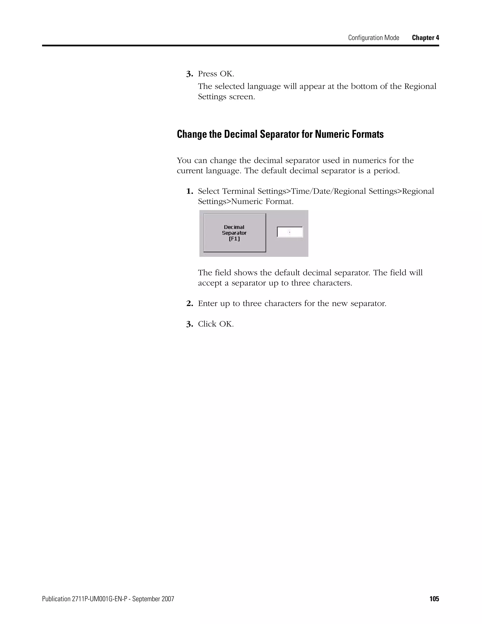
![Publication 2711P-UM001G-EN-P - September 2007 59
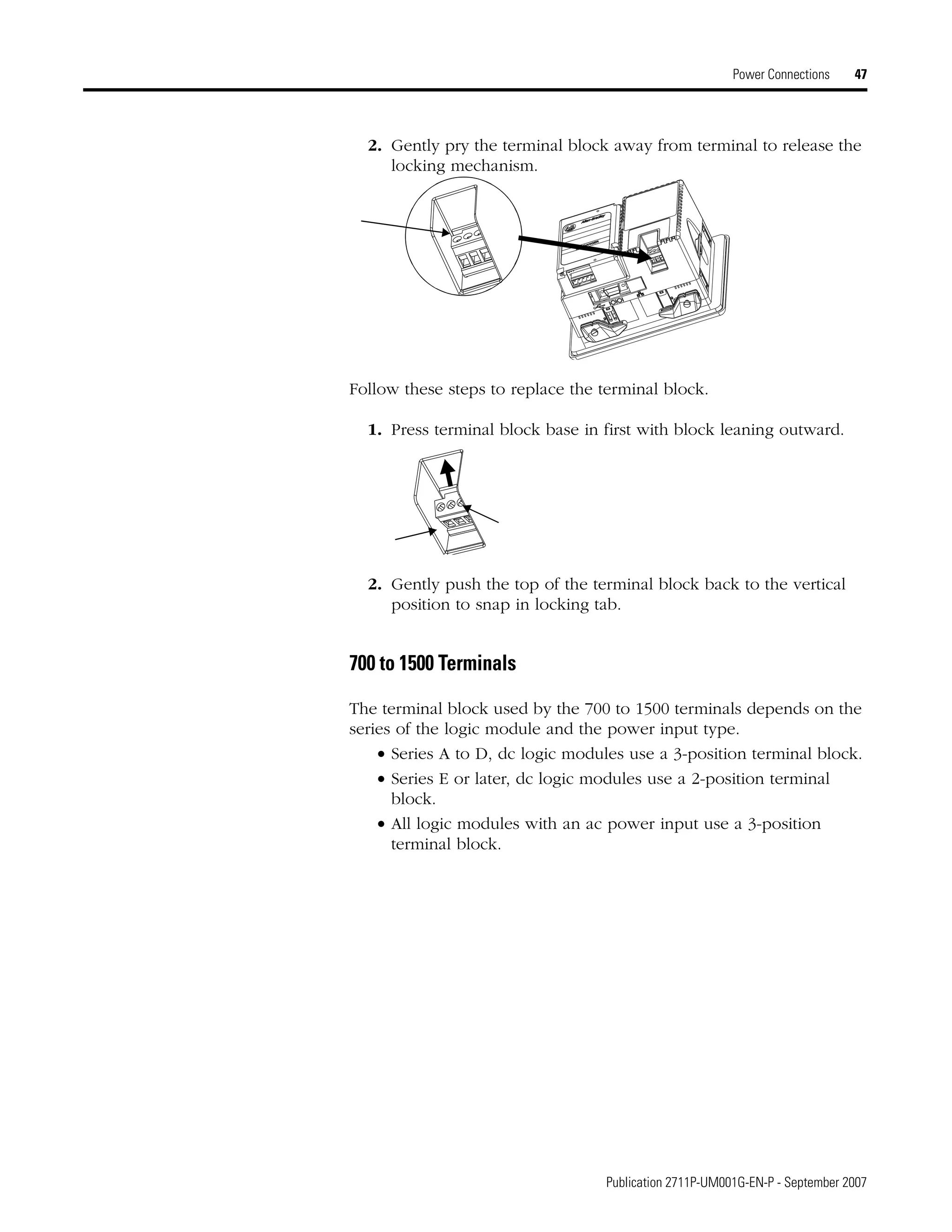
Configuration Mode Chapter 4
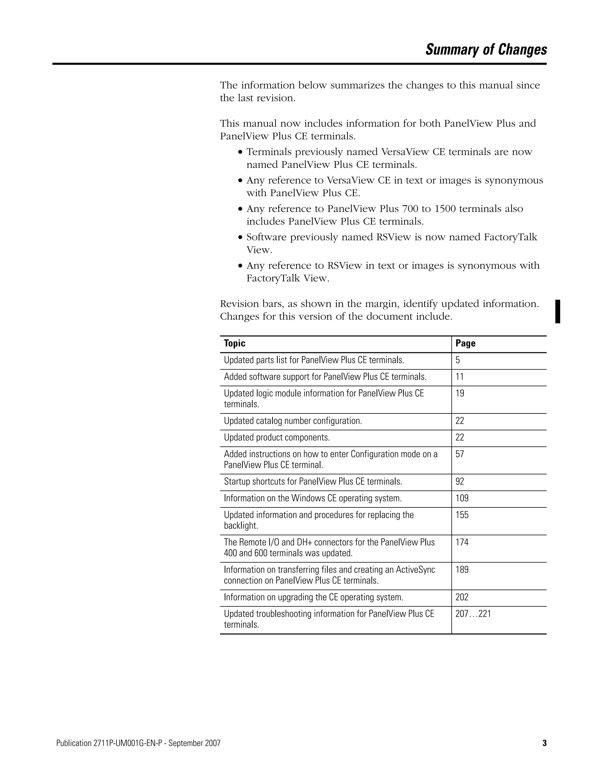
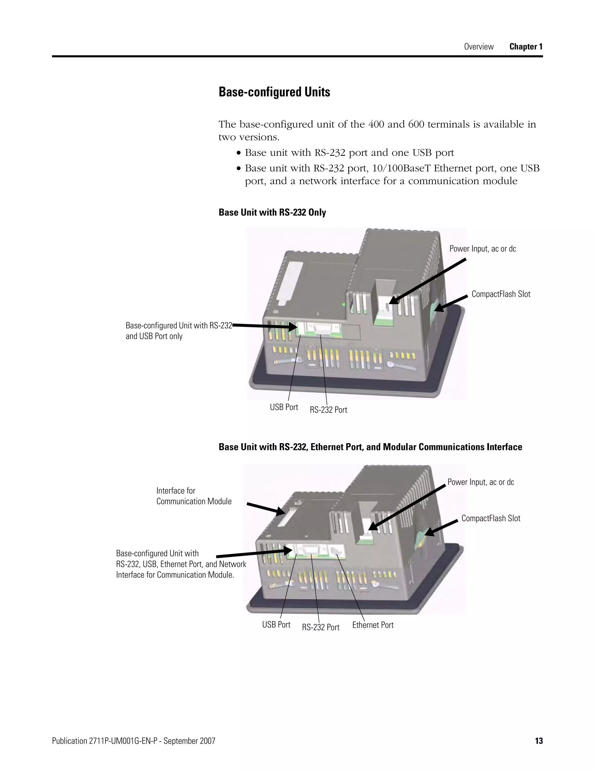
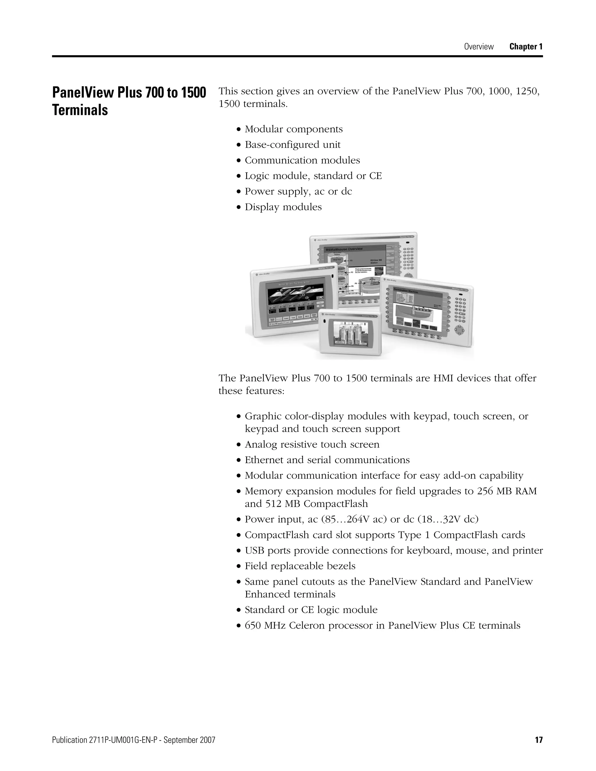
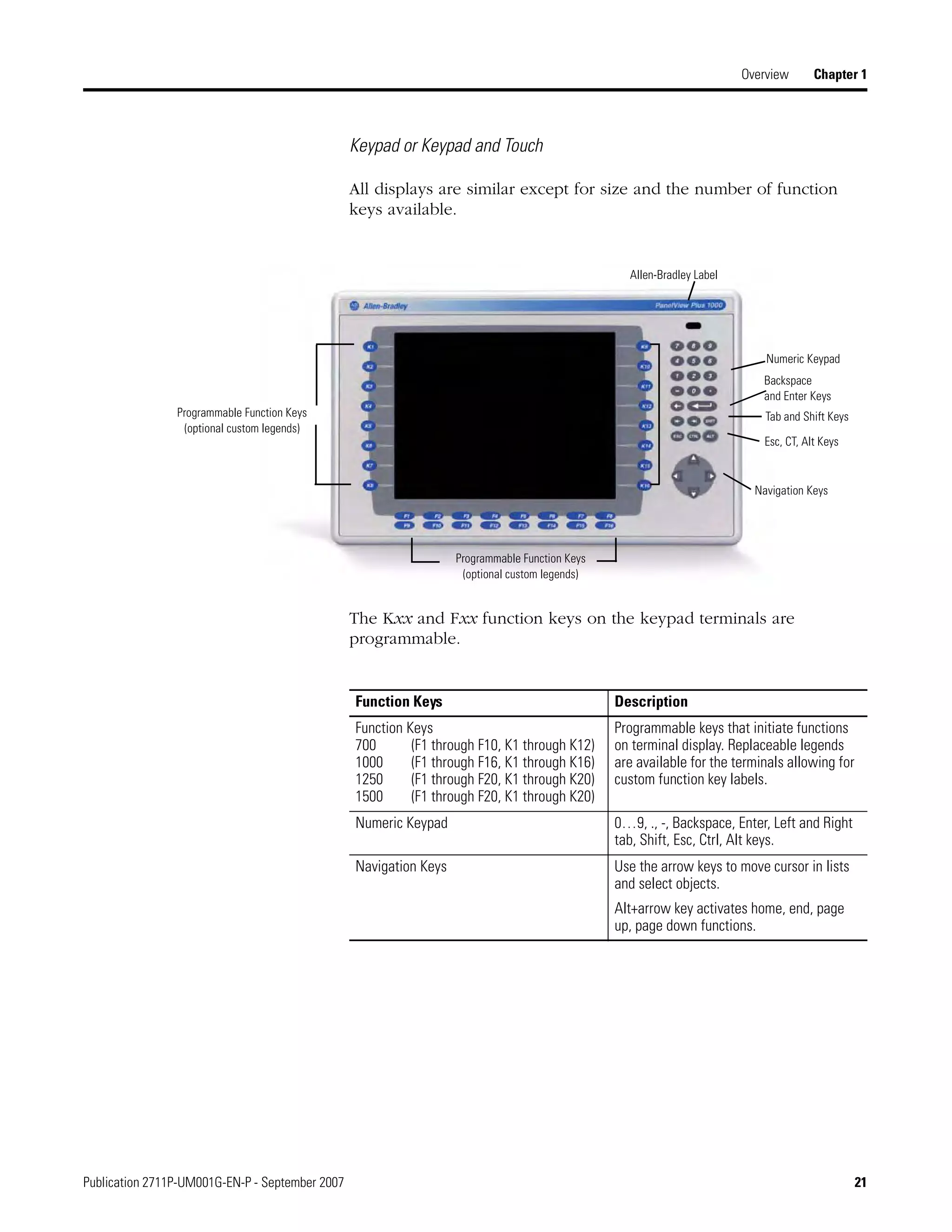
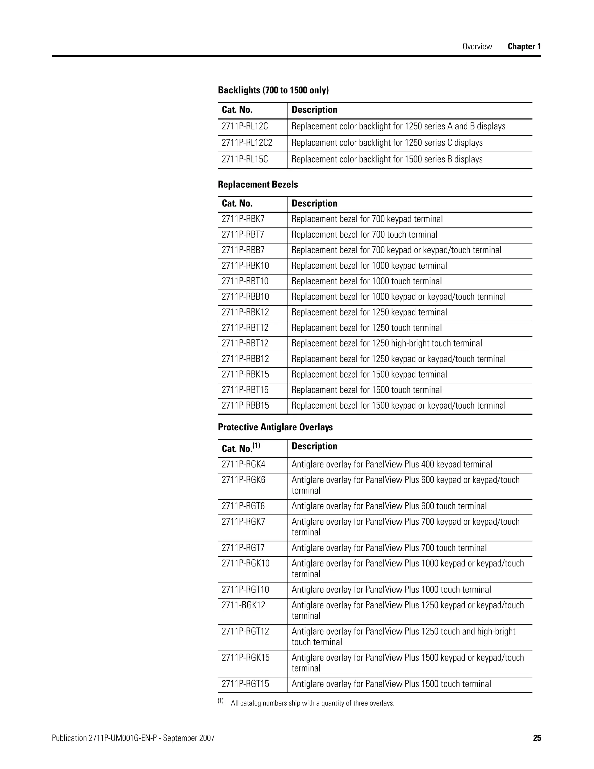
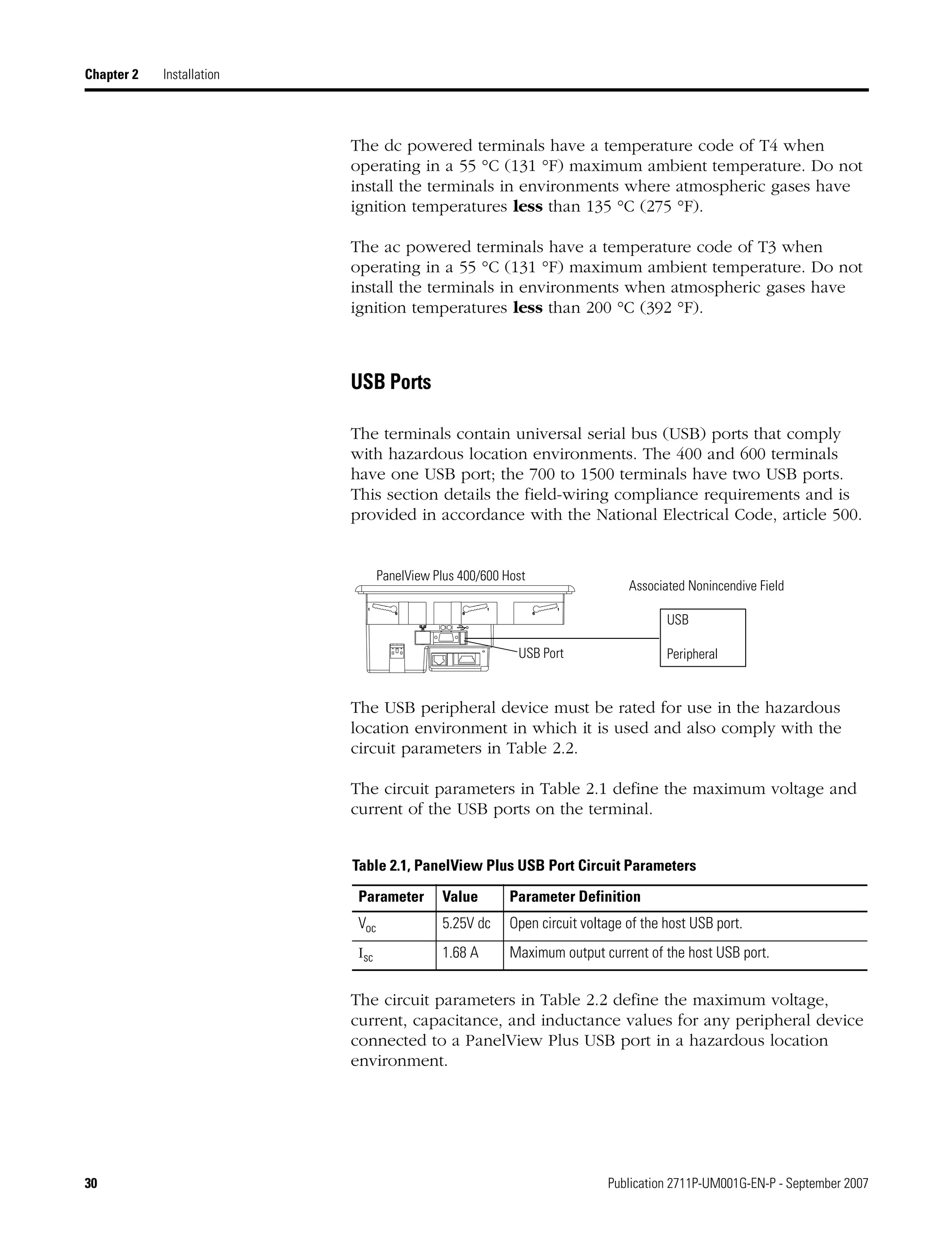
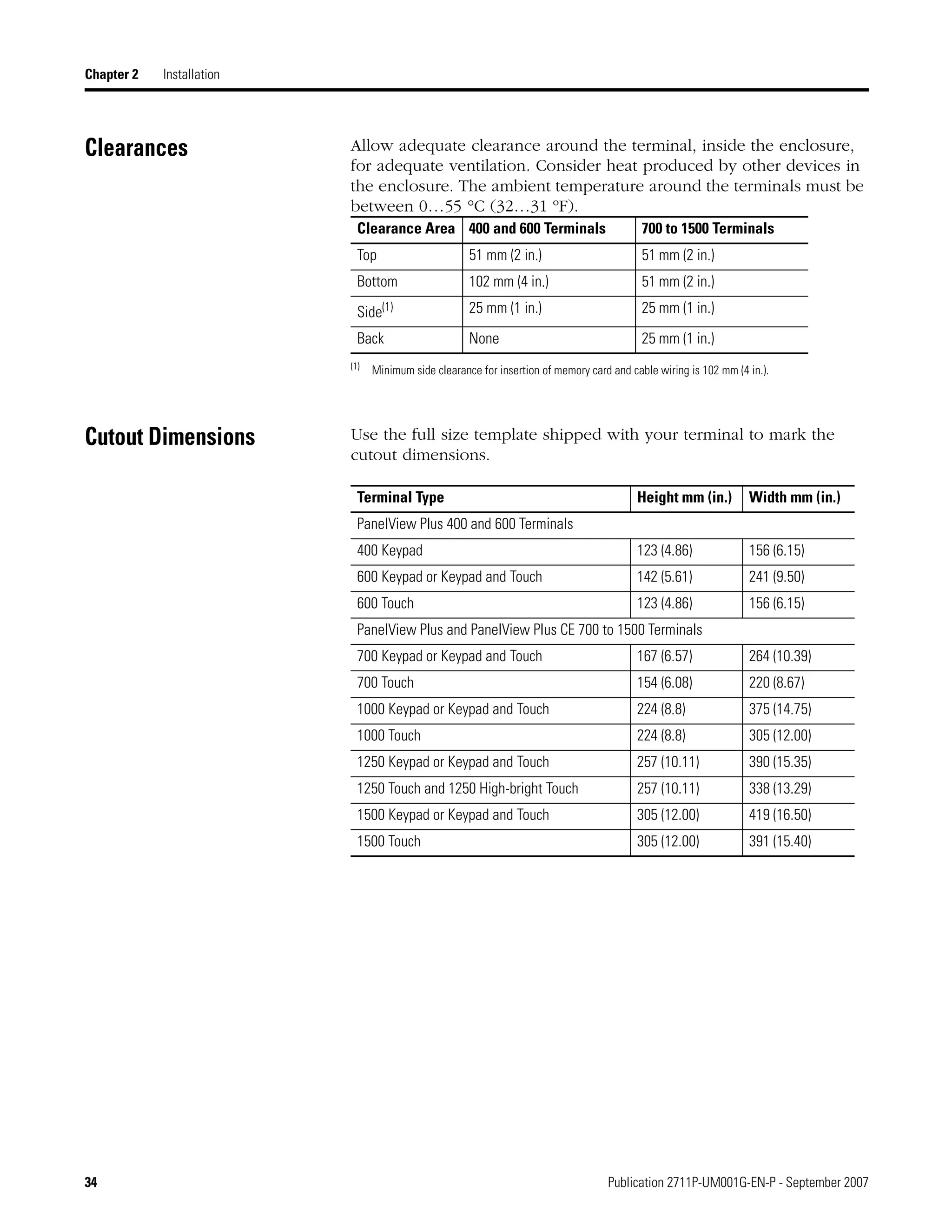
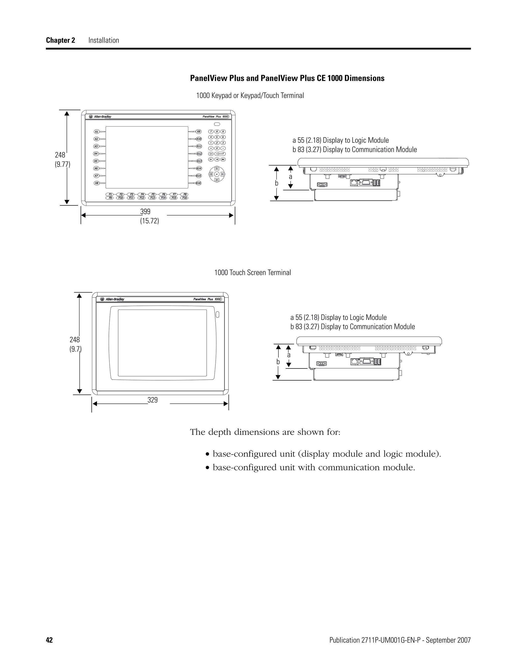
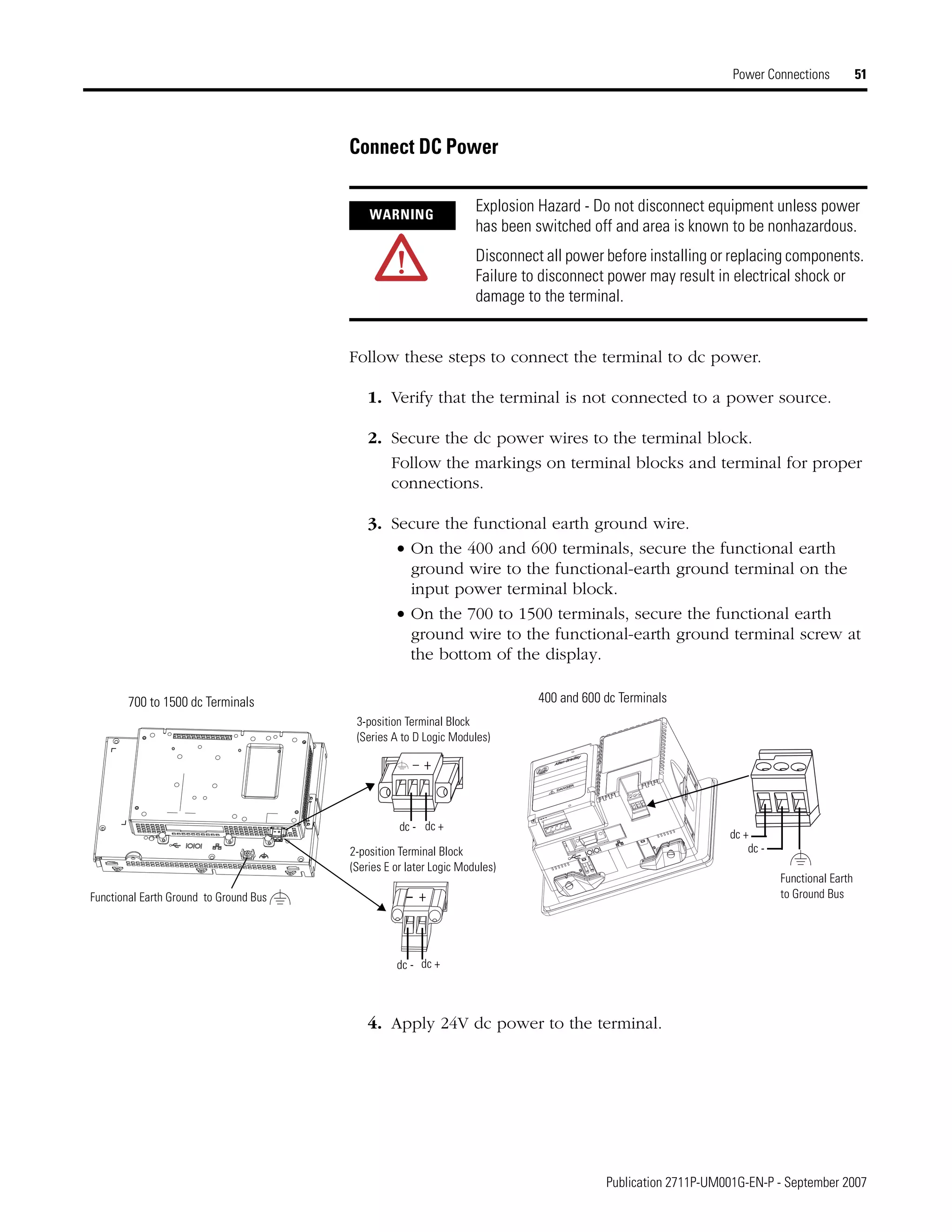
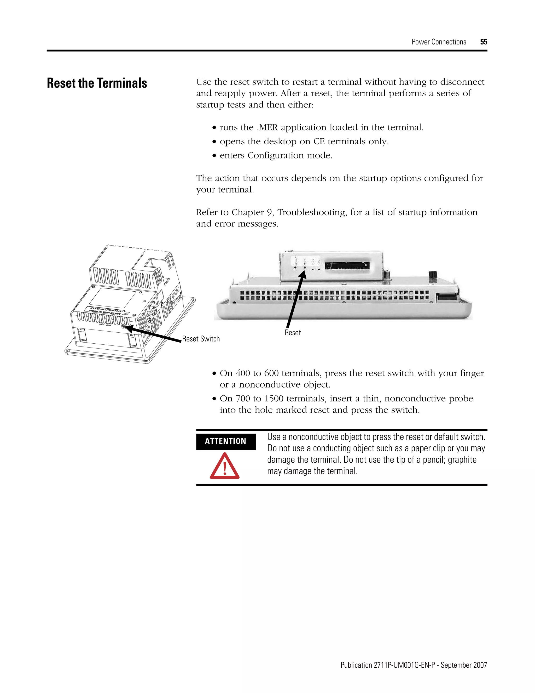
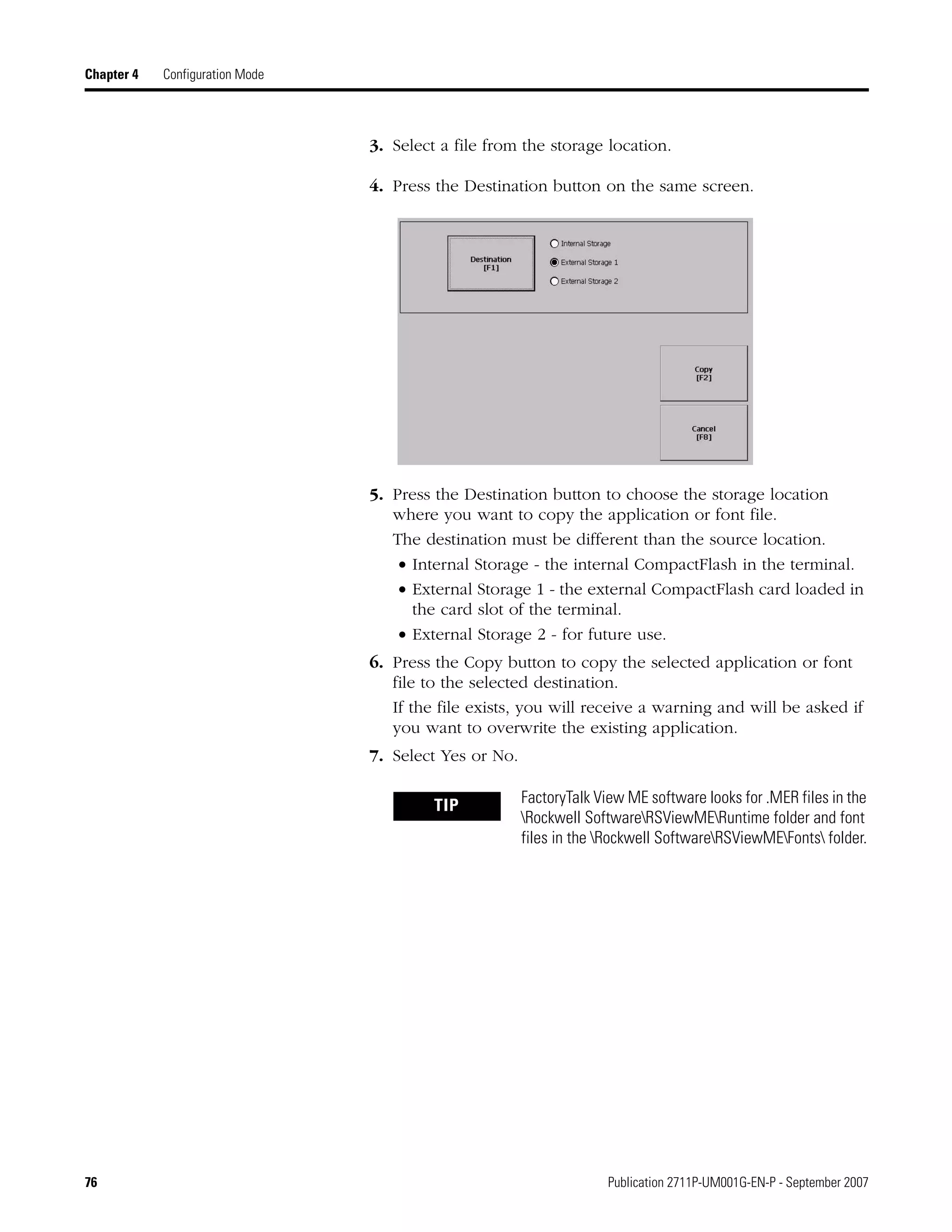
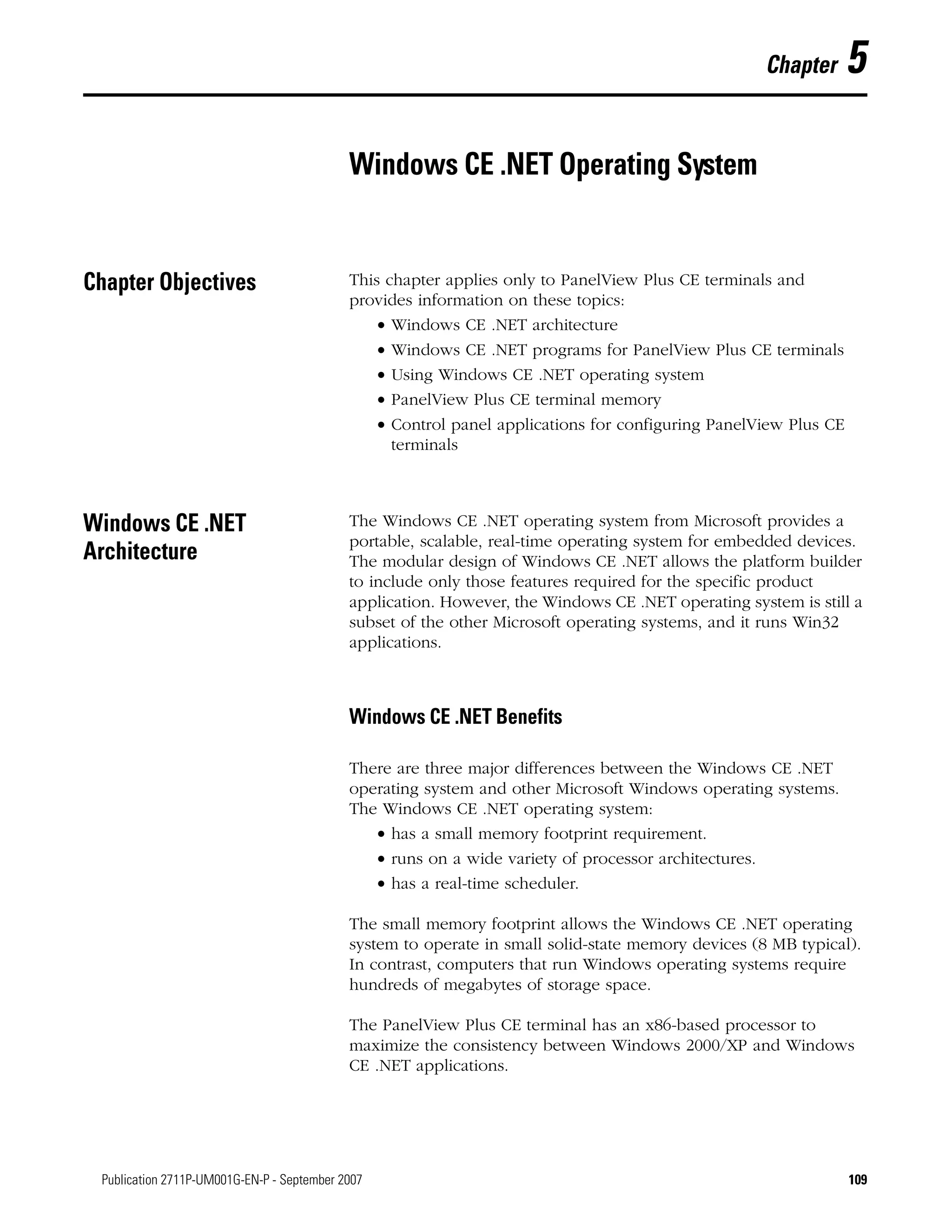
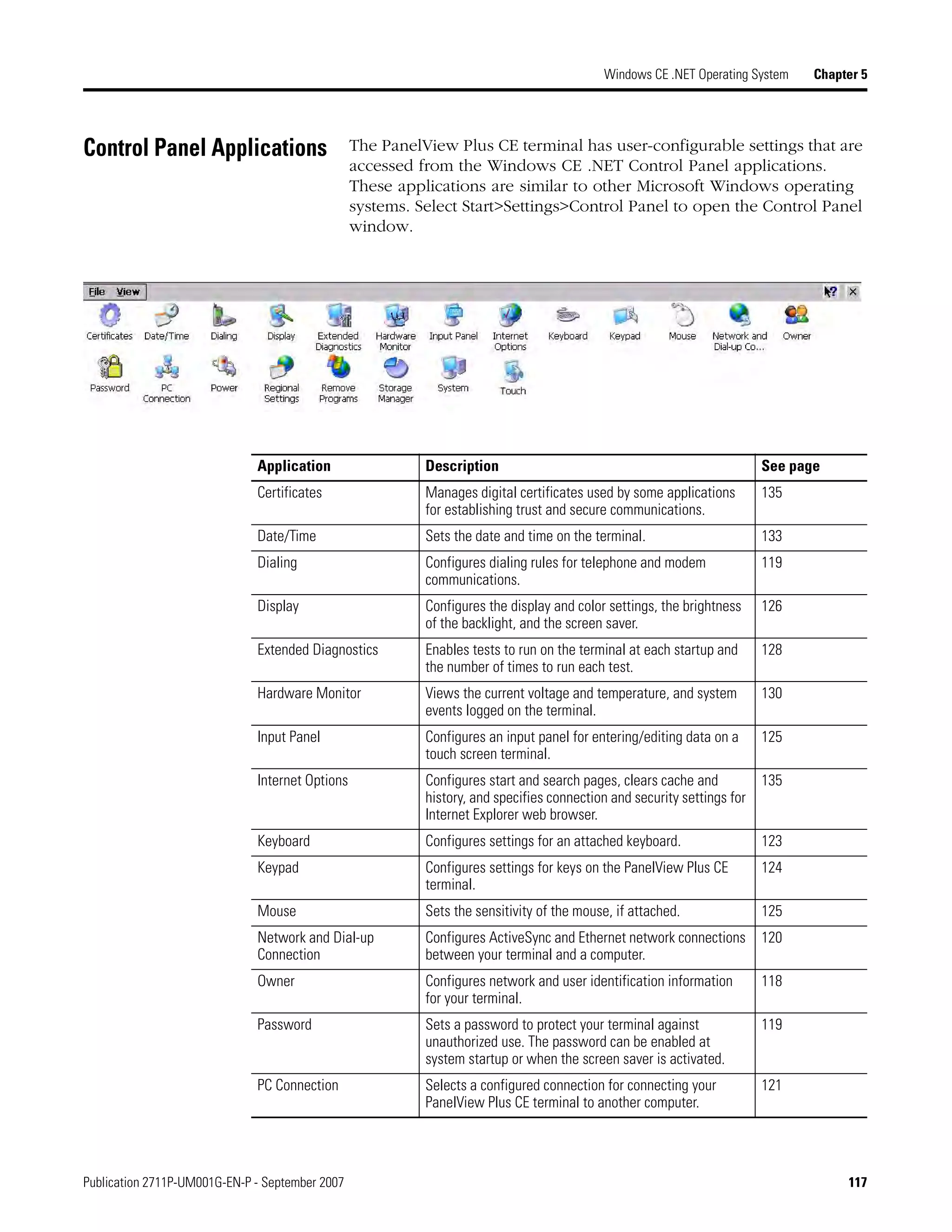
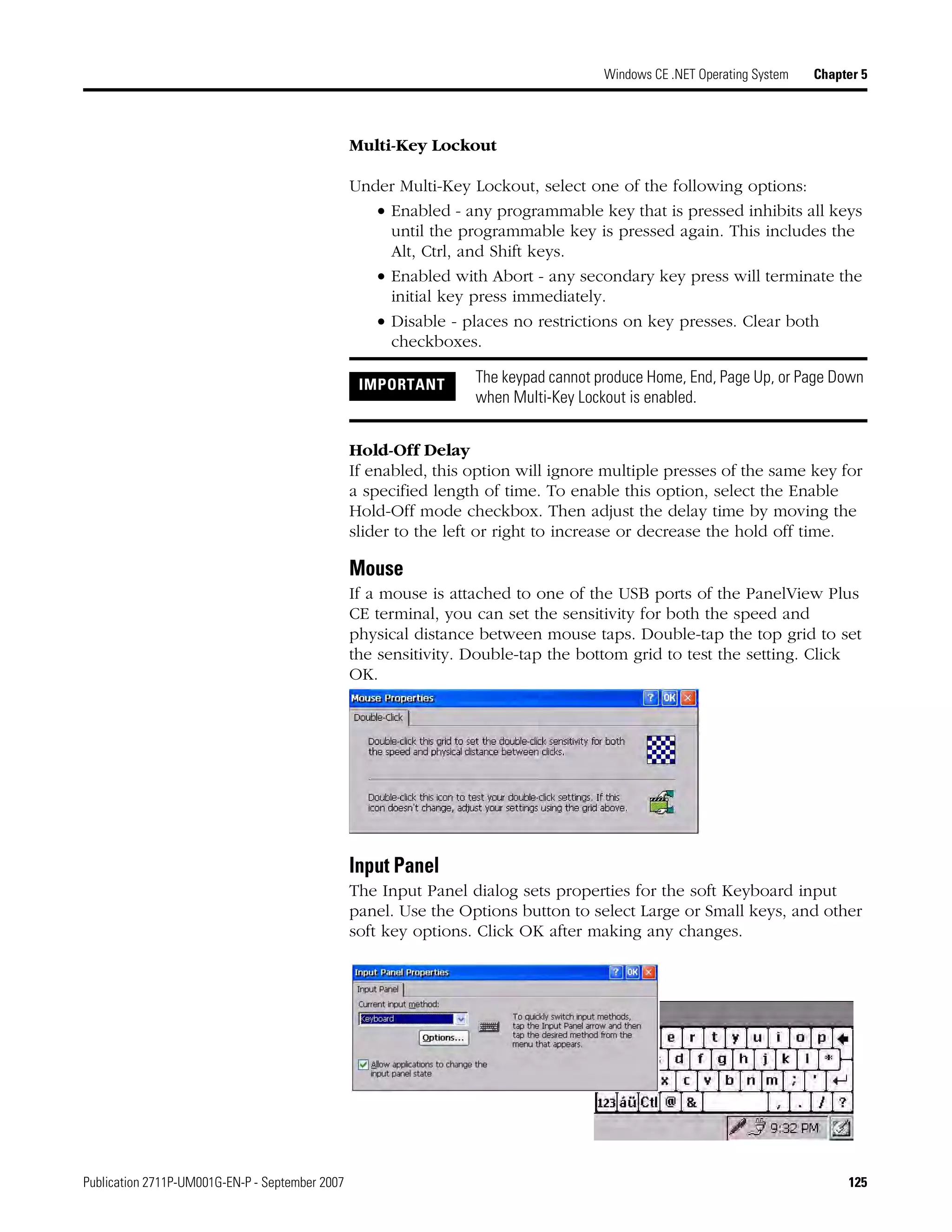
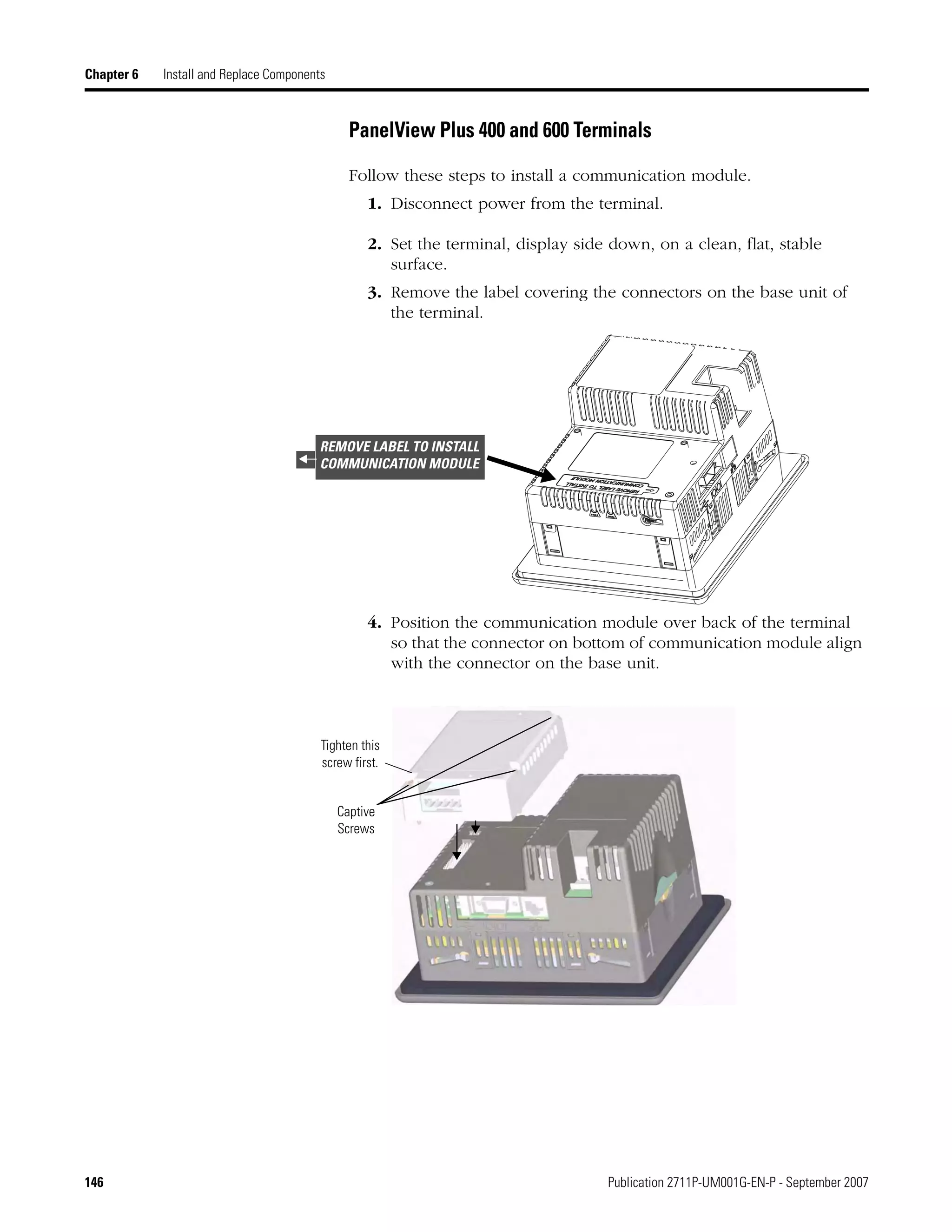
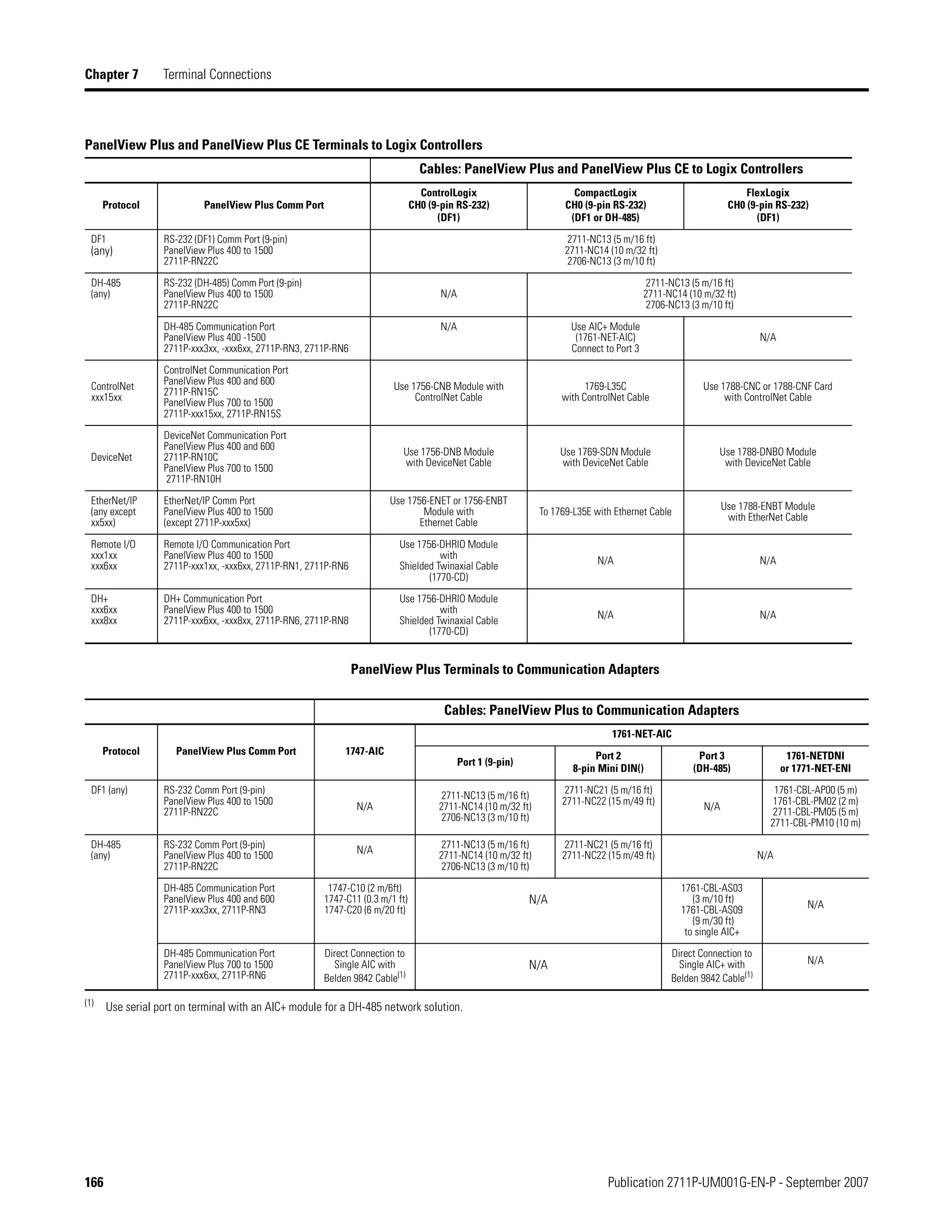
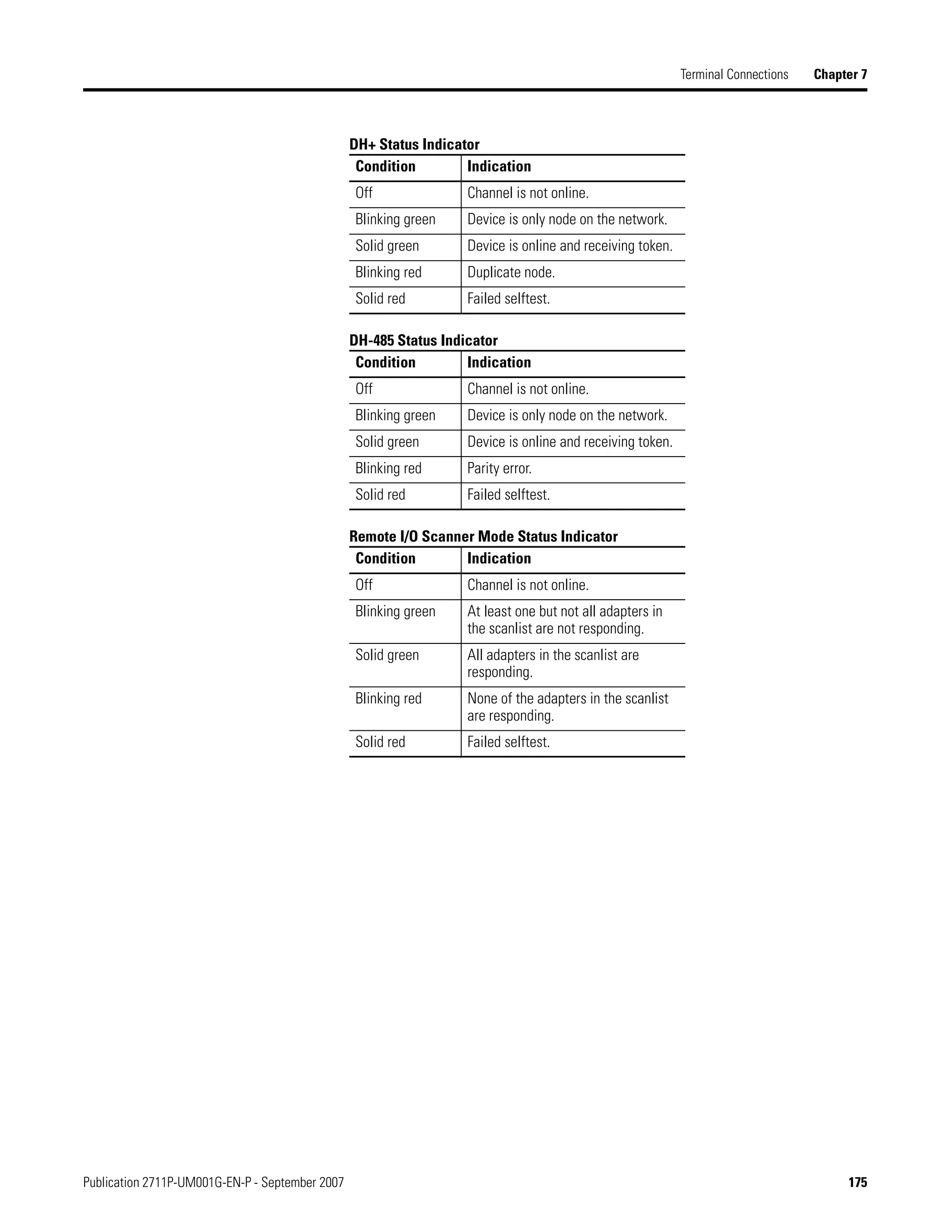
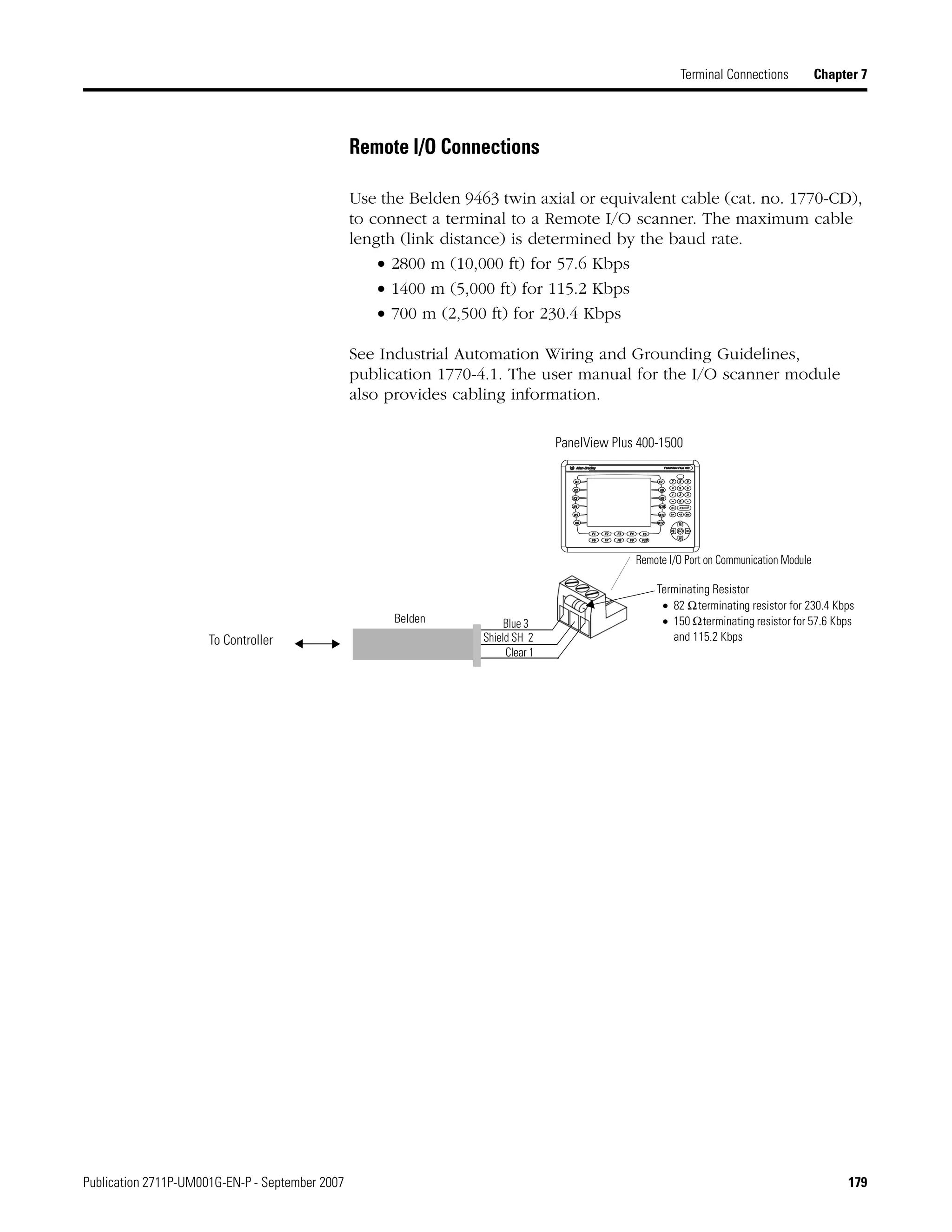
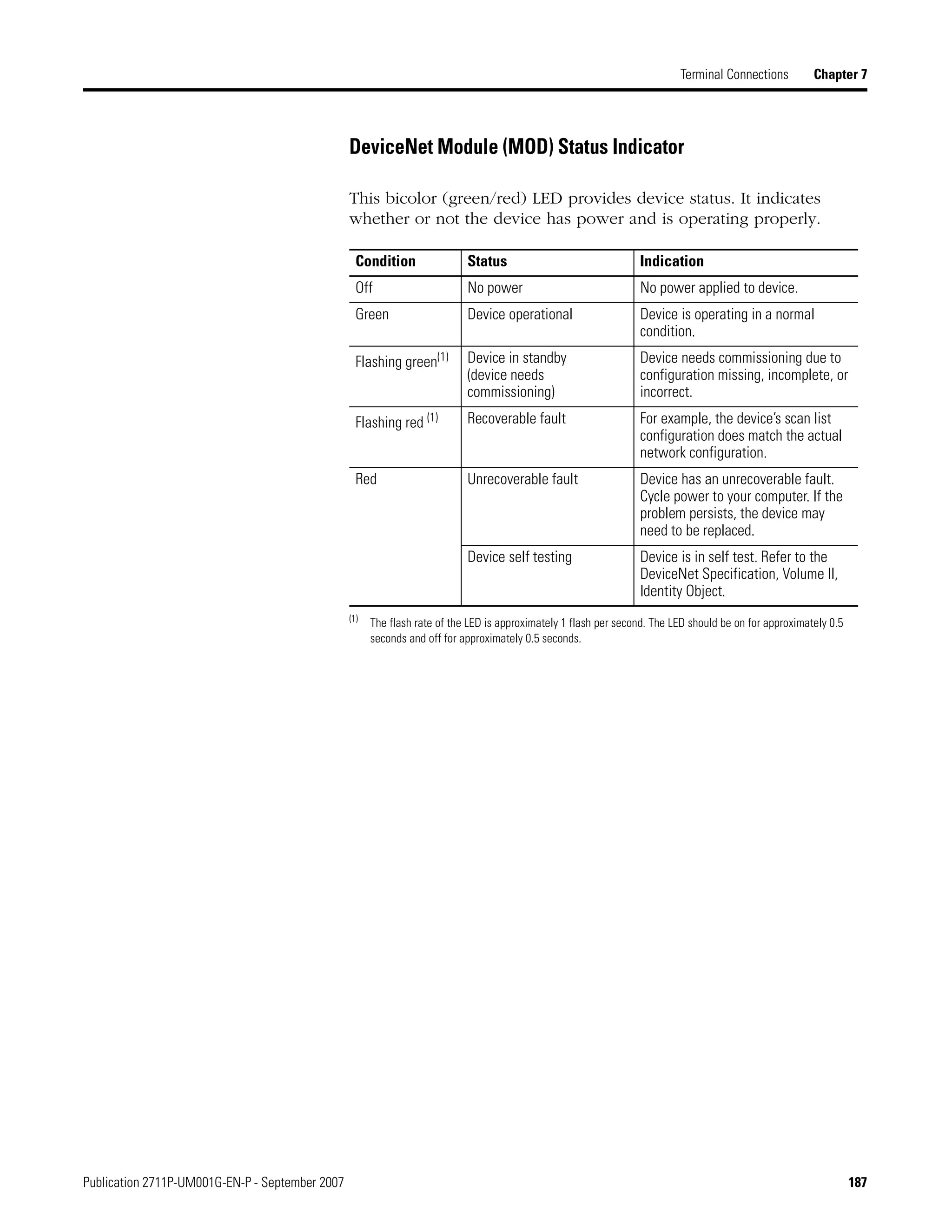
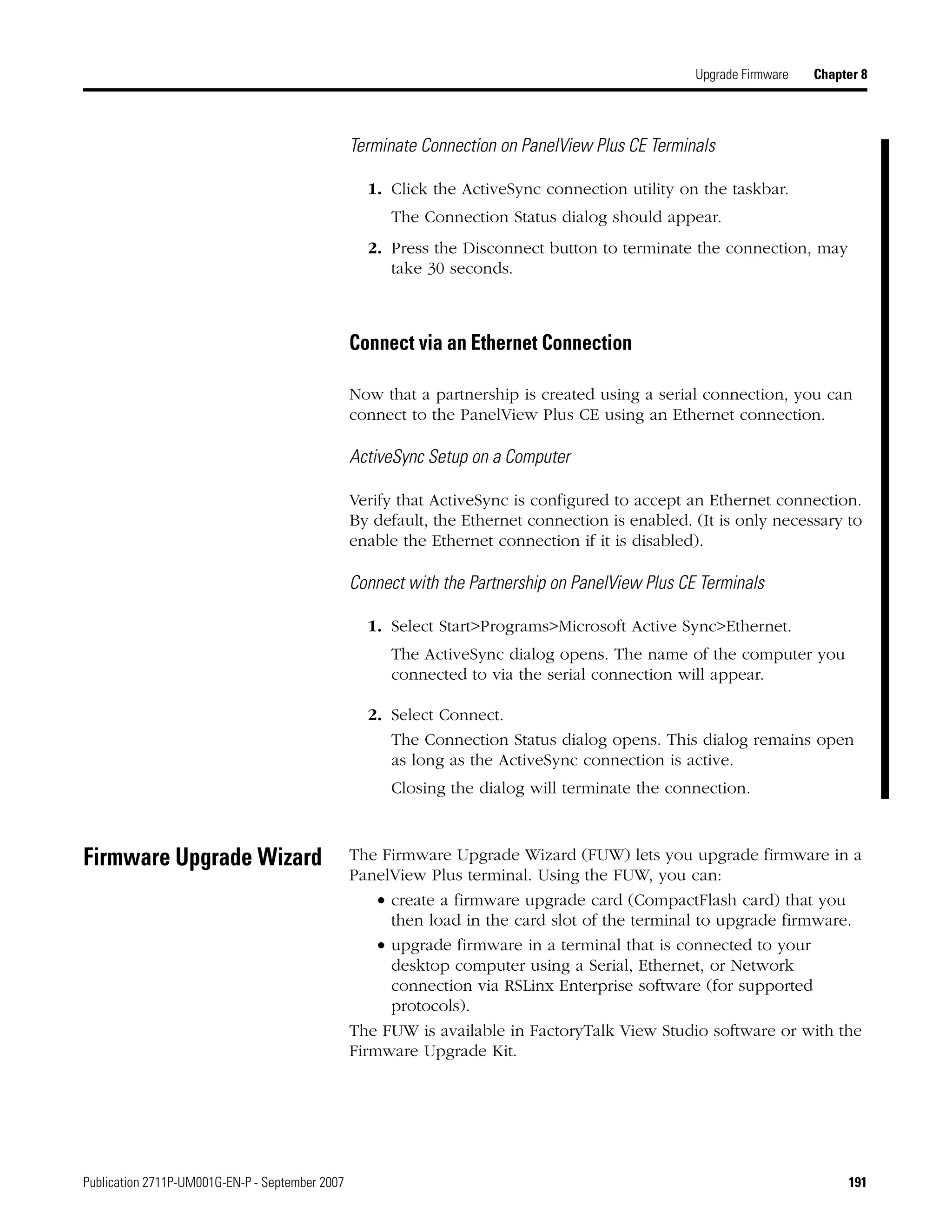
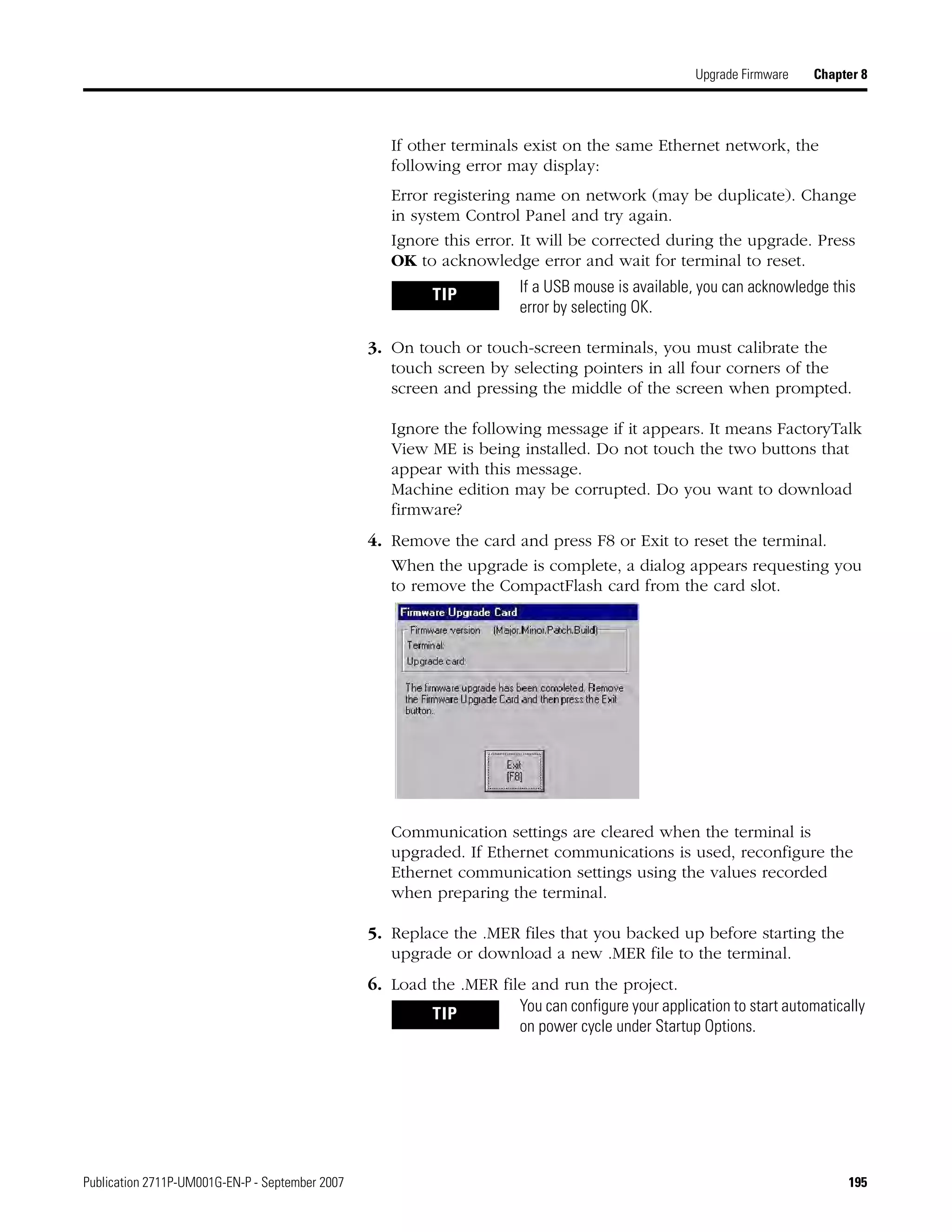
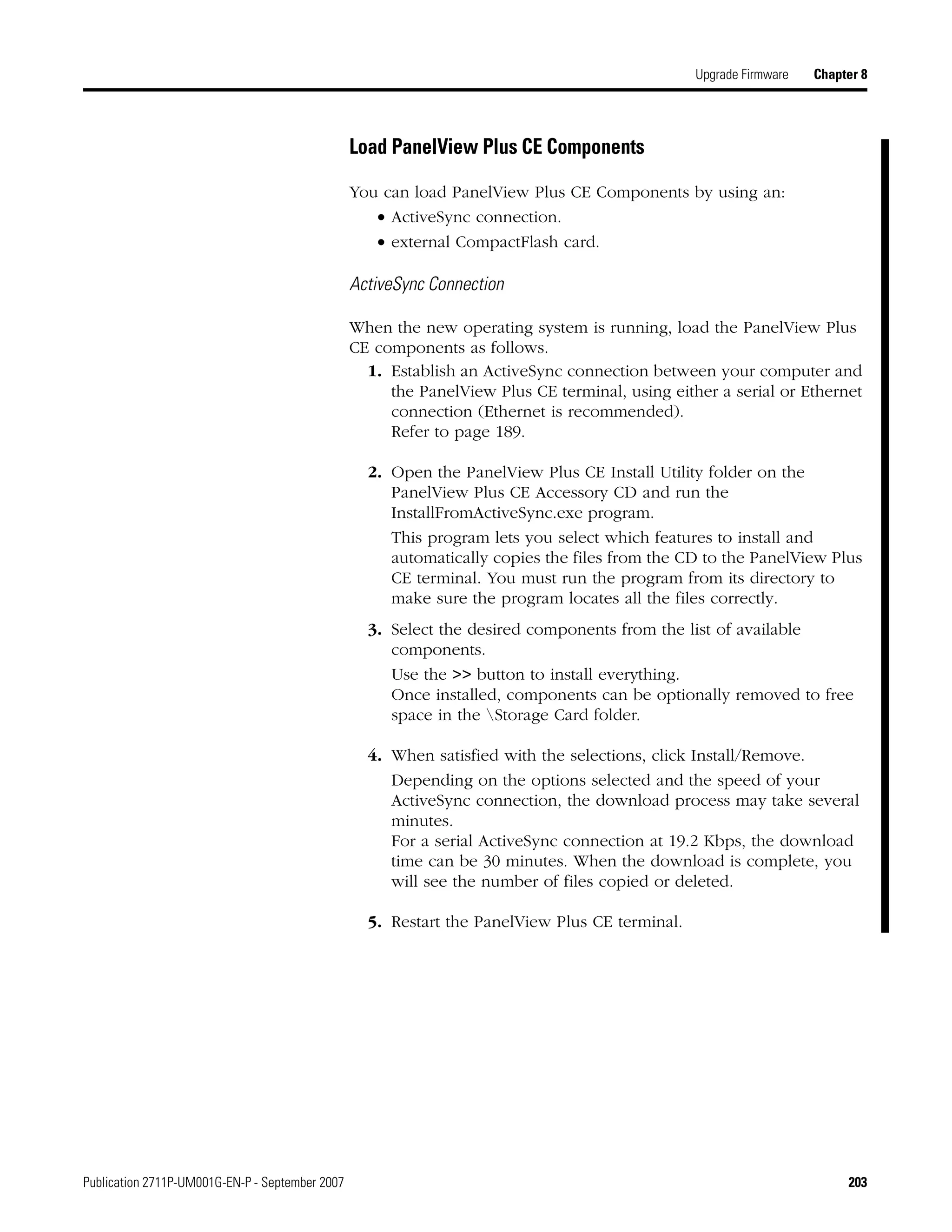
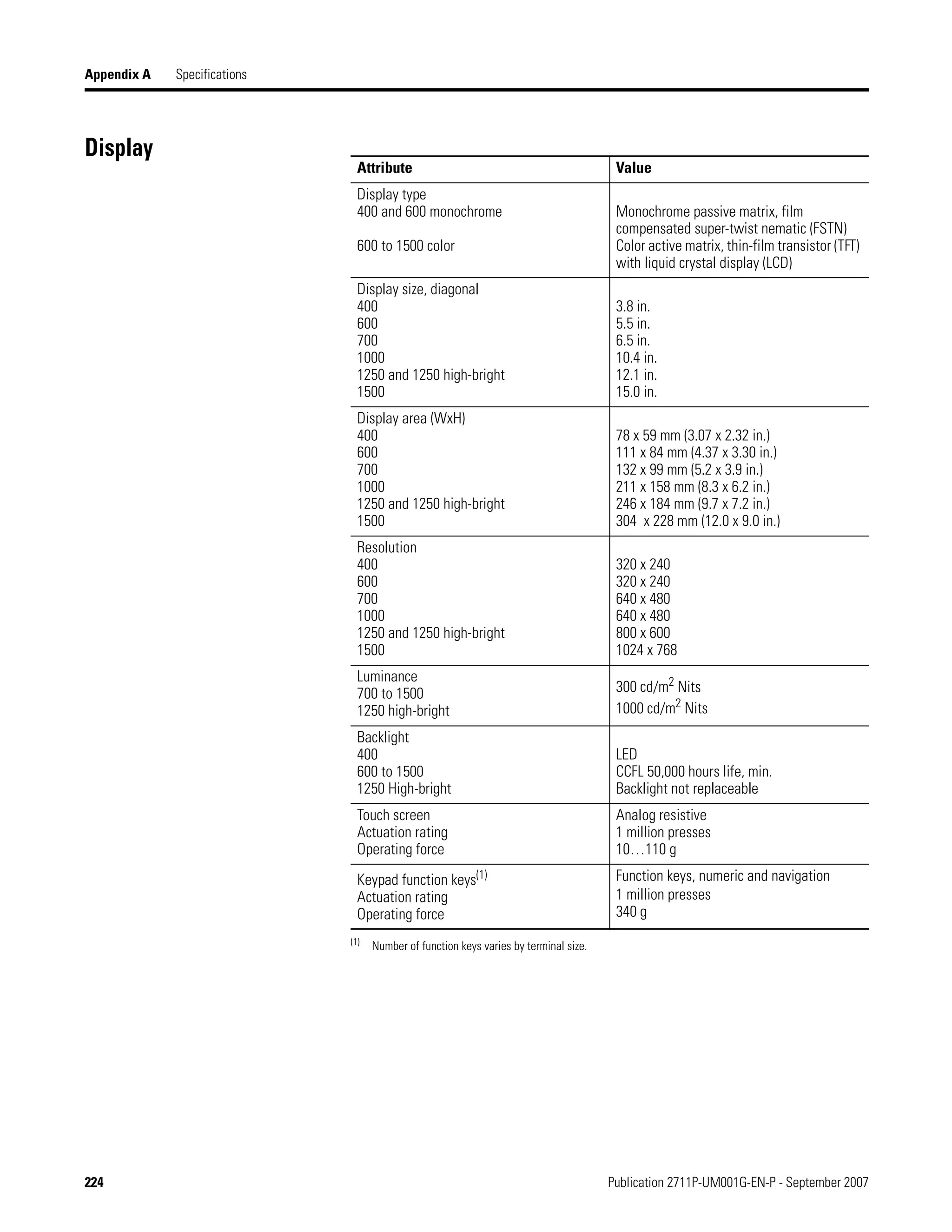
Navigation Buttons
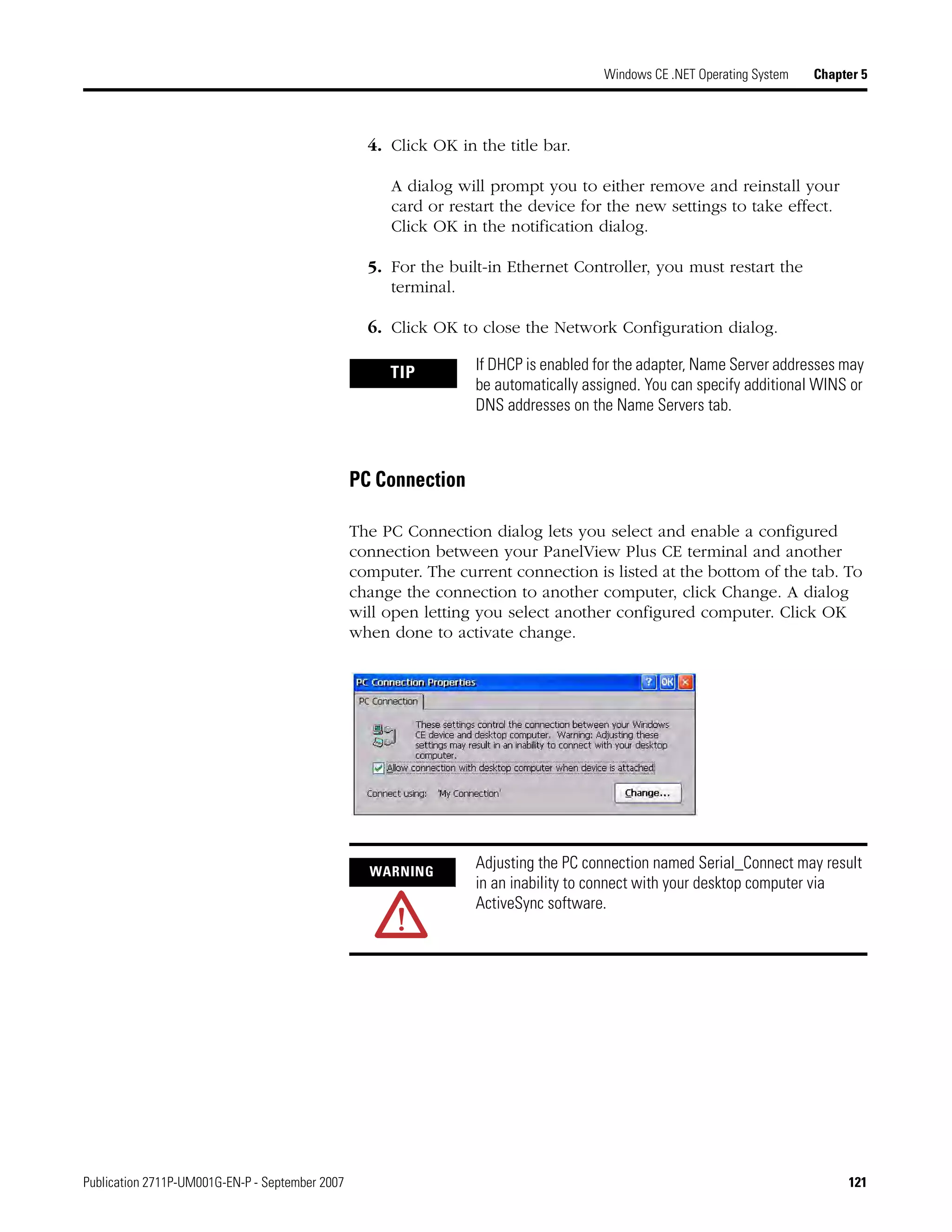
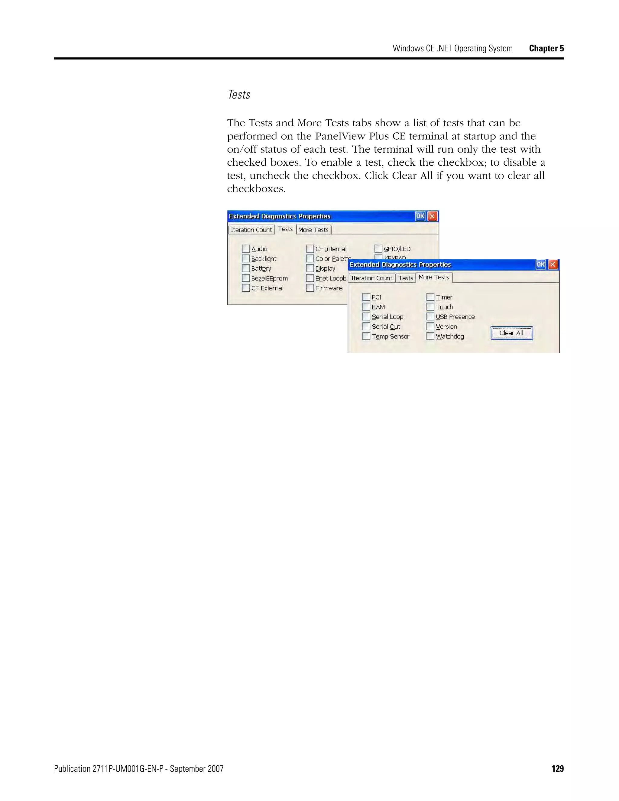
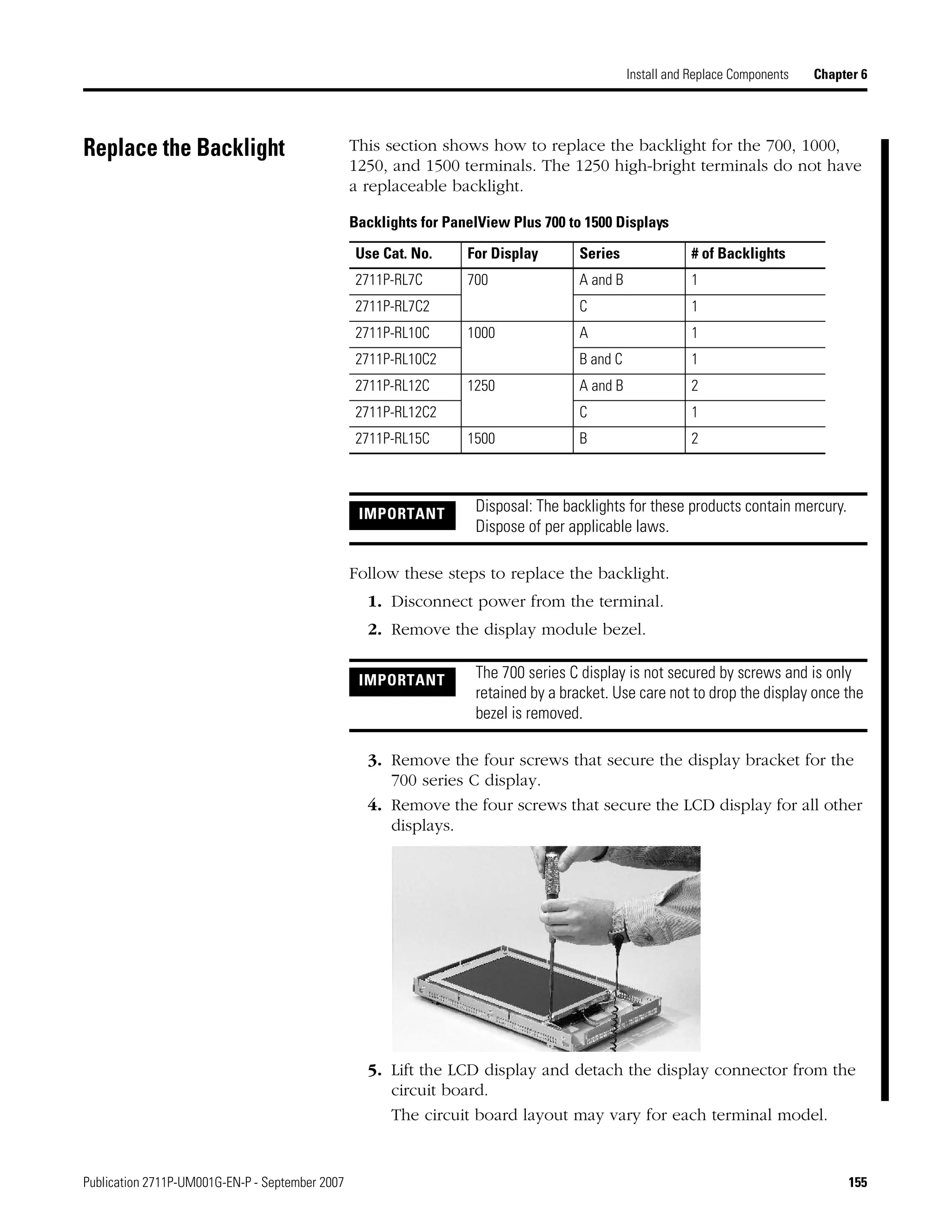
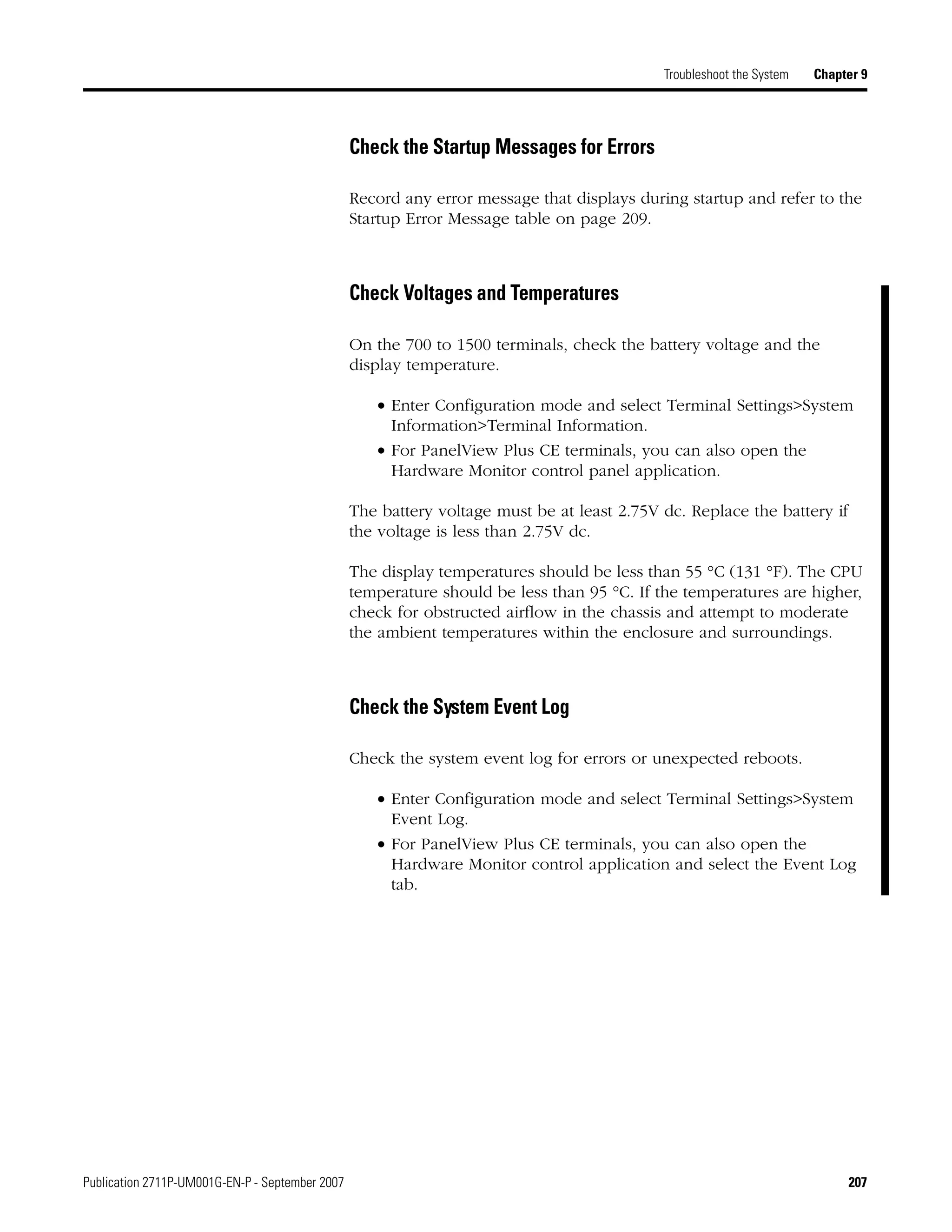
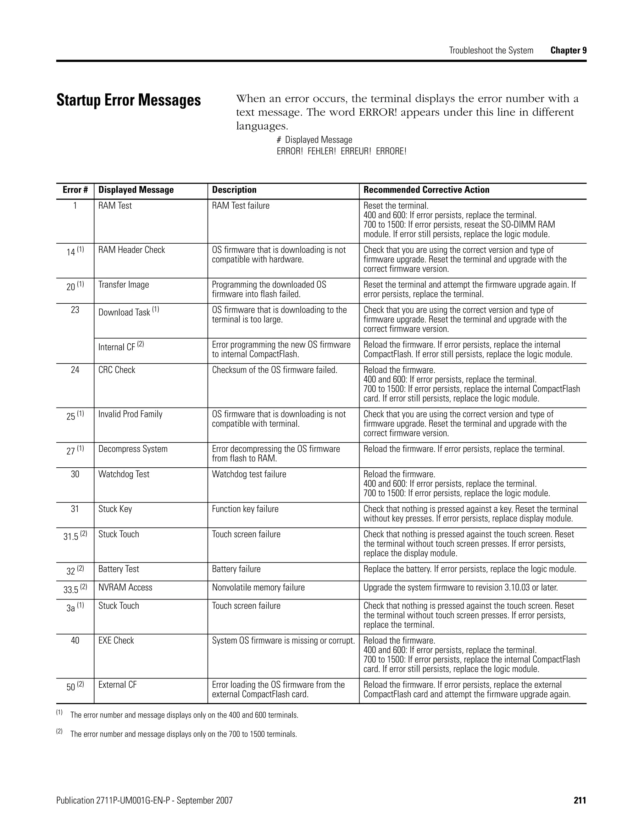
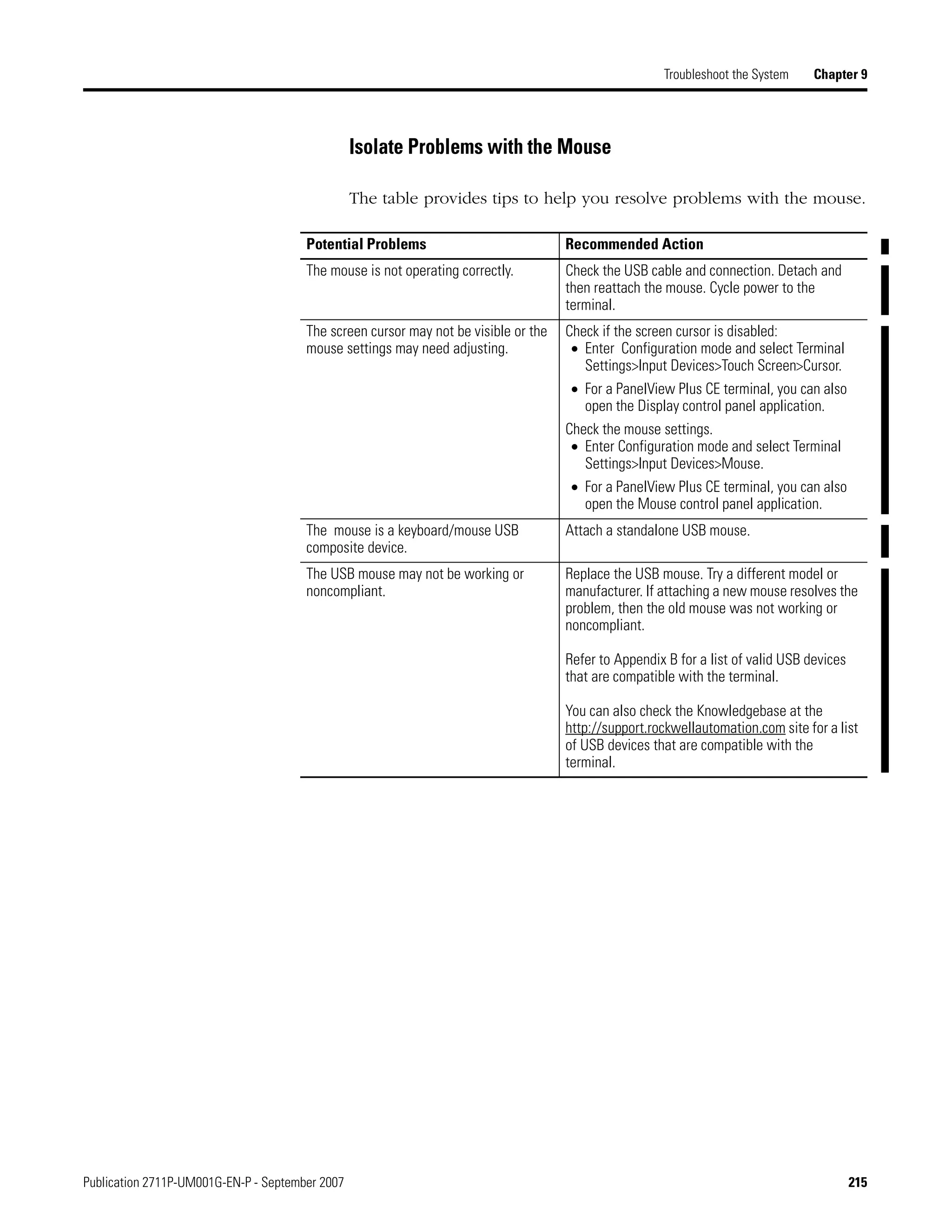
Screen buttons are used for data entry and navigation.
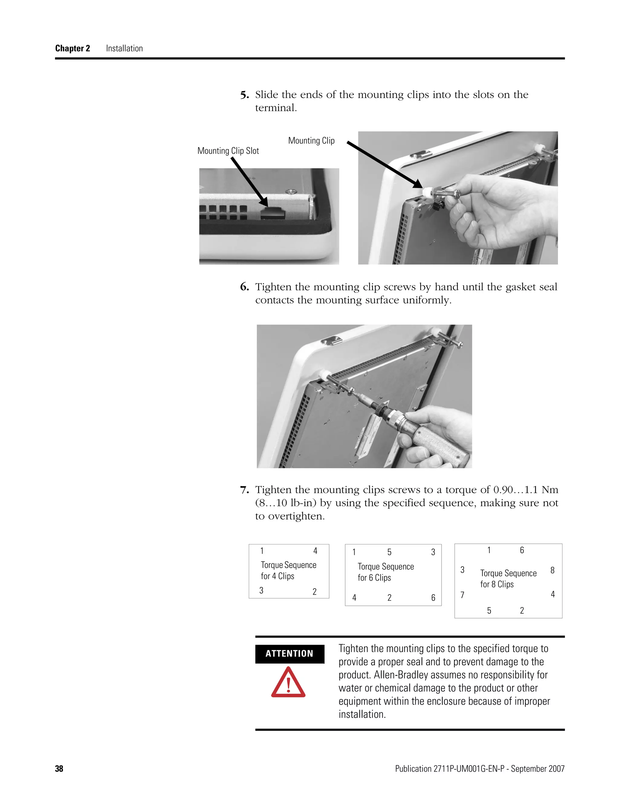
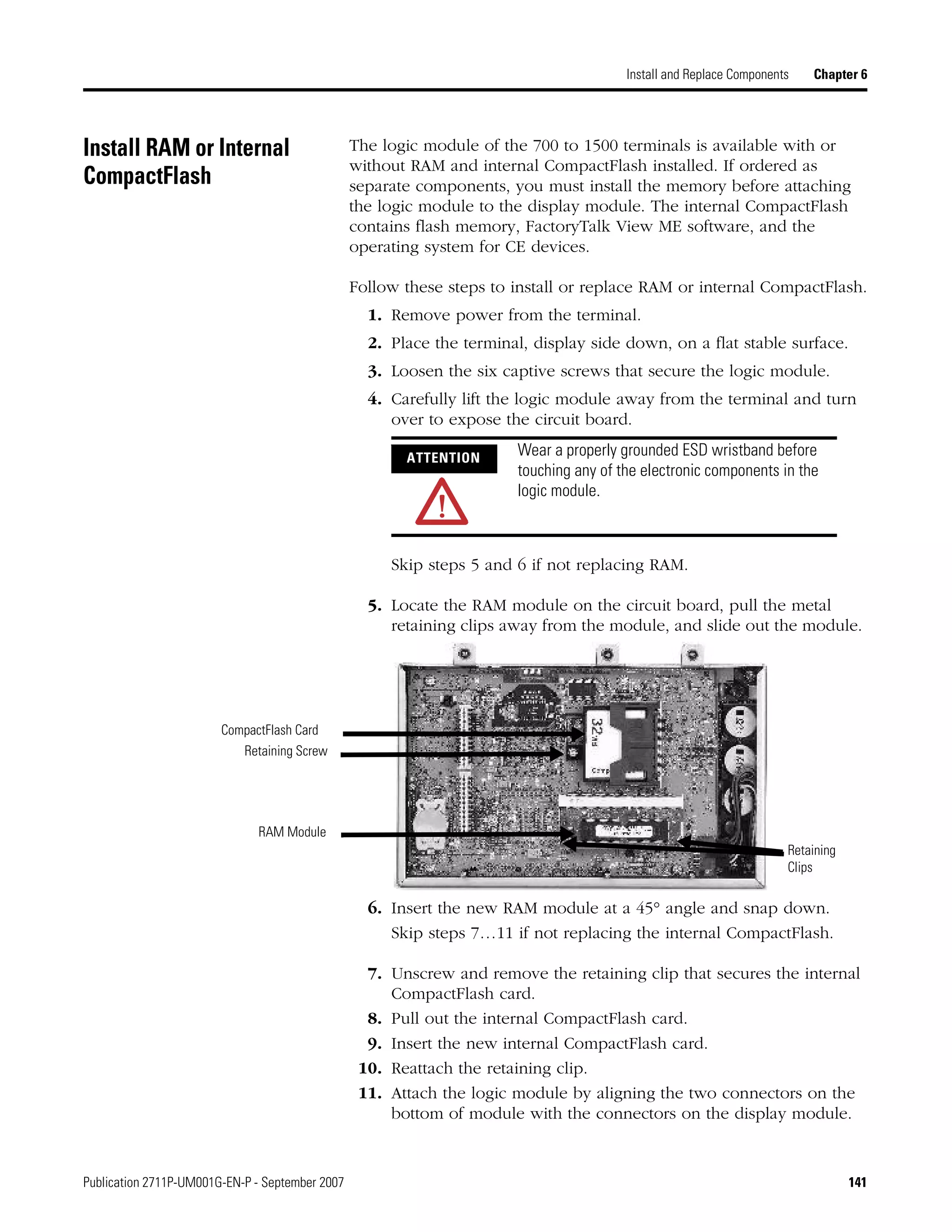
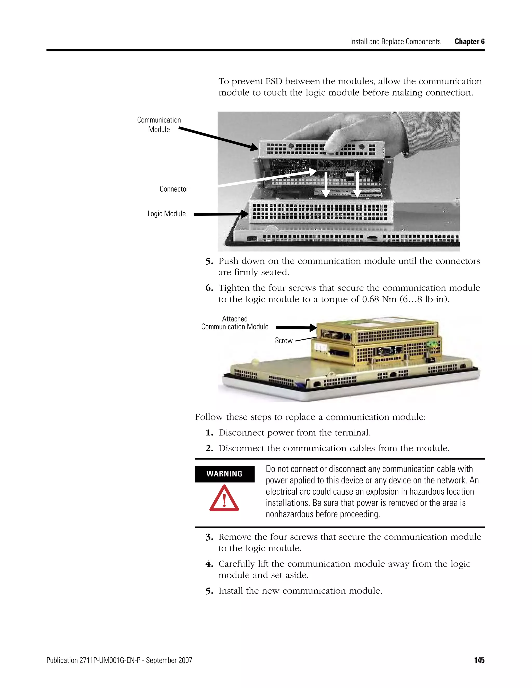
• On touch-screen terminals, tap the button with your finger or
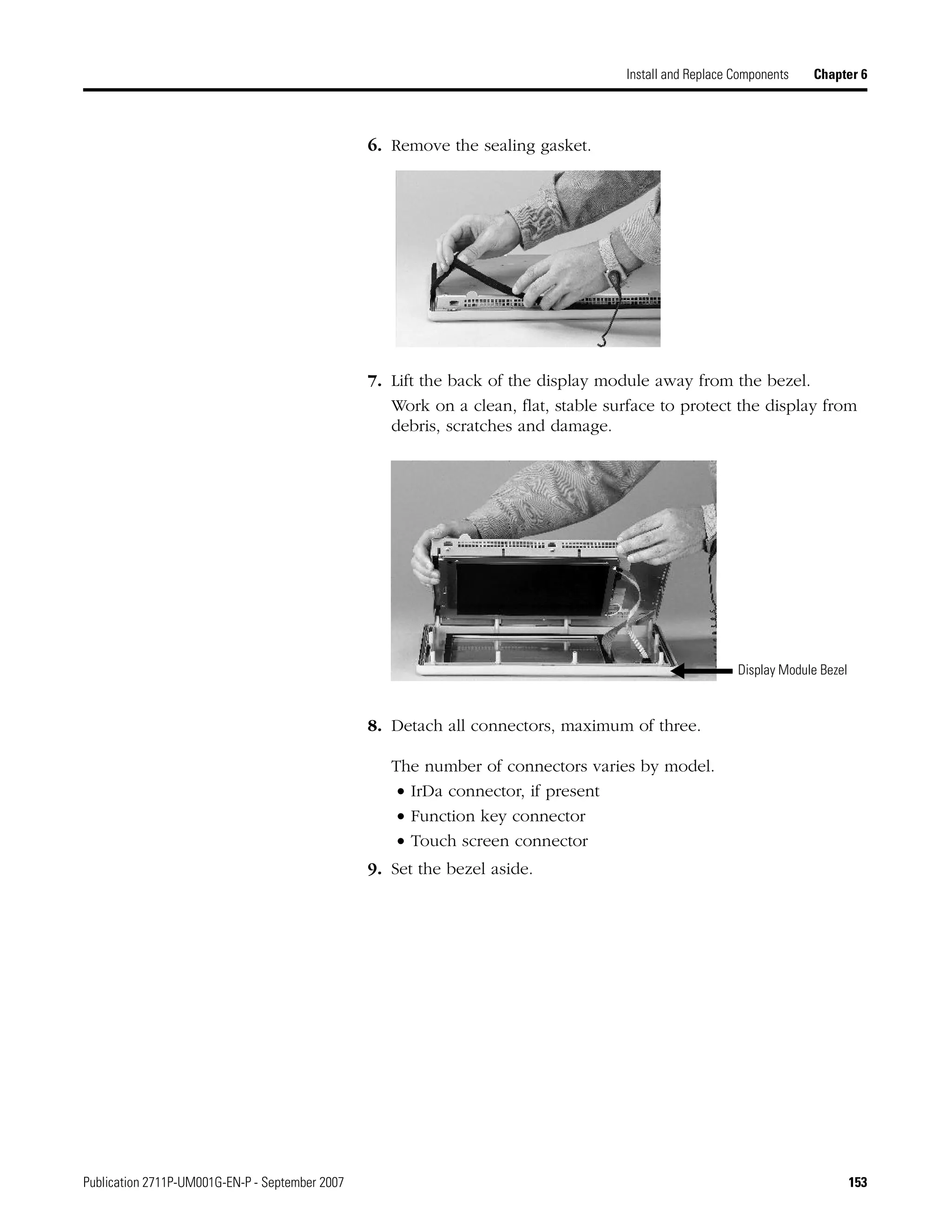
stylus.
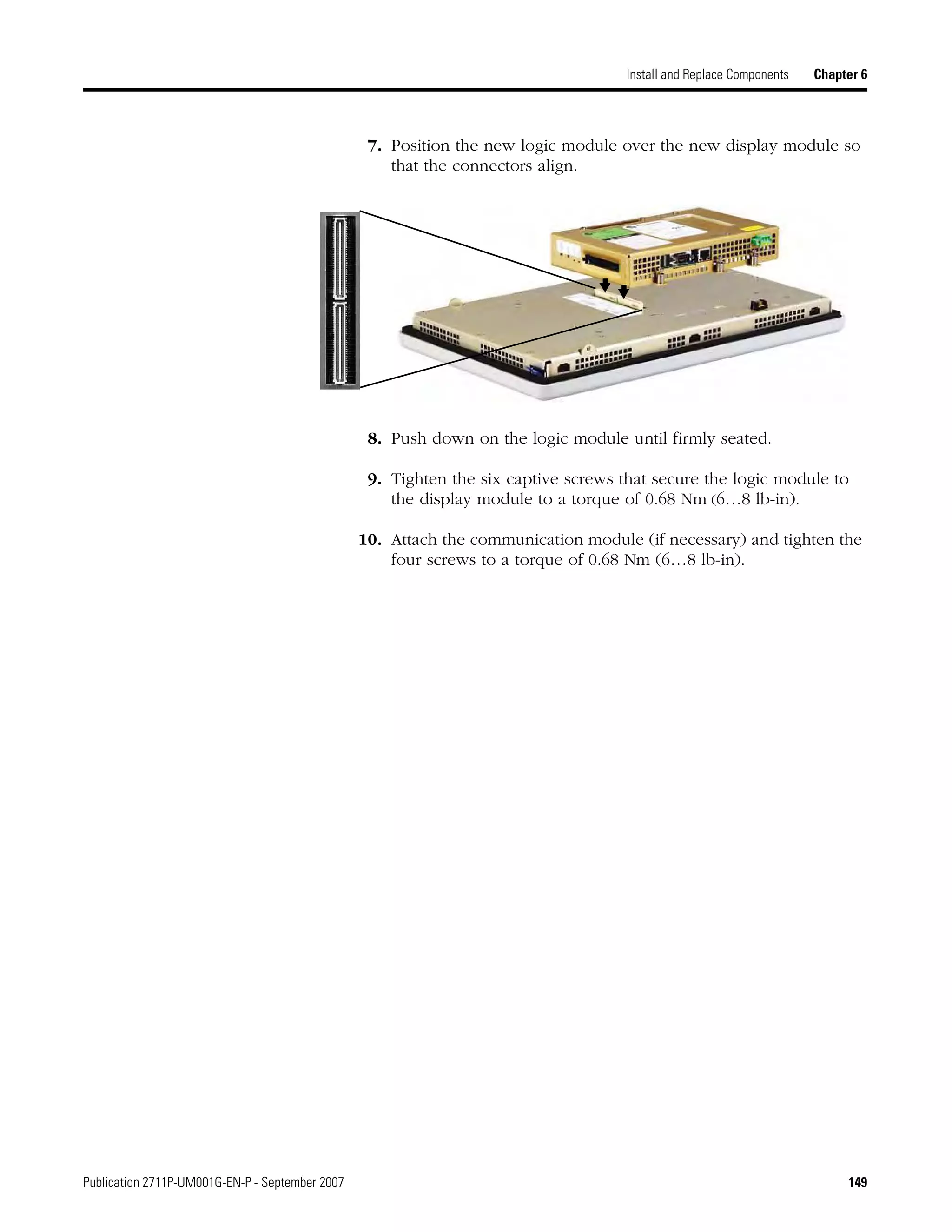
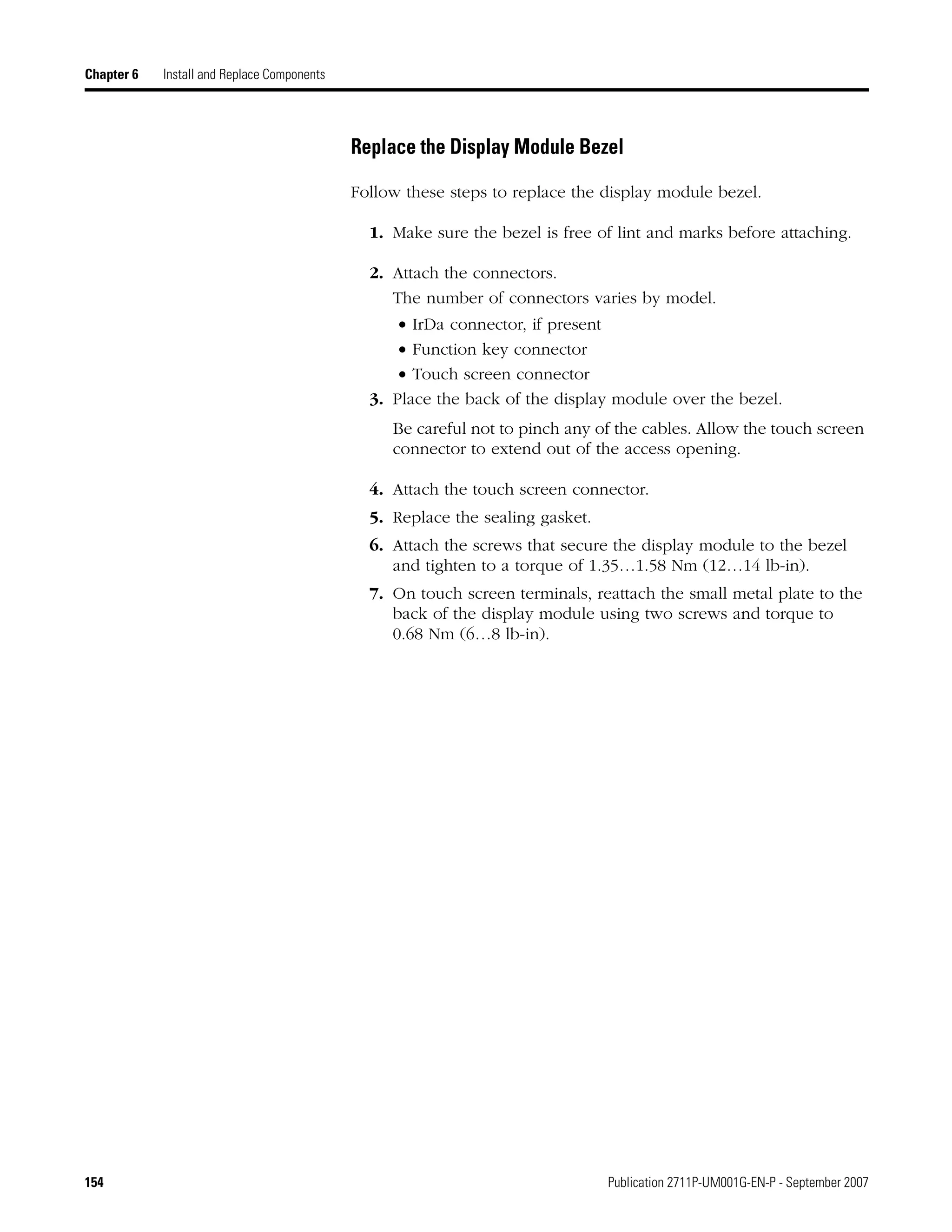
• On keypad terminals, select the function key listed on the
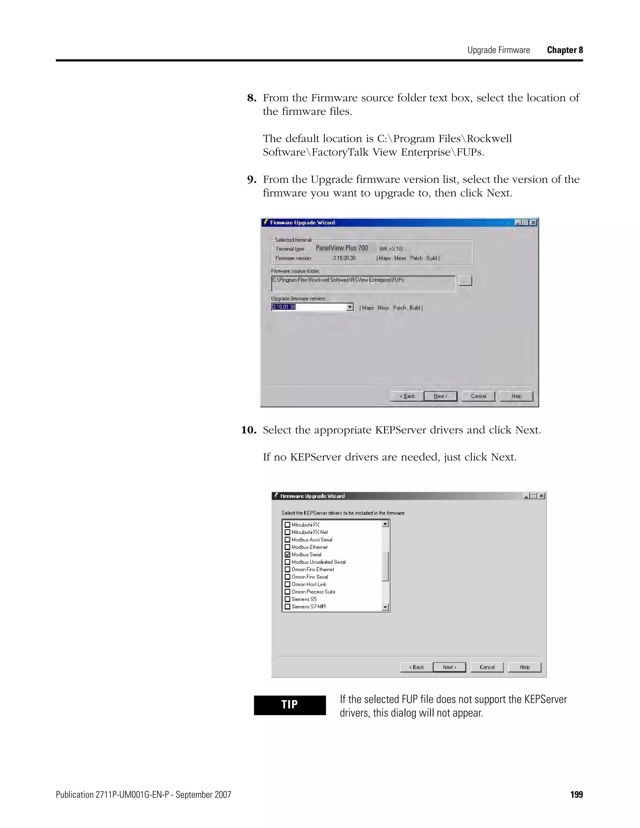
button, or in some cases, the corresponding key on the keypad.
• If a mouse is attached, click a button.
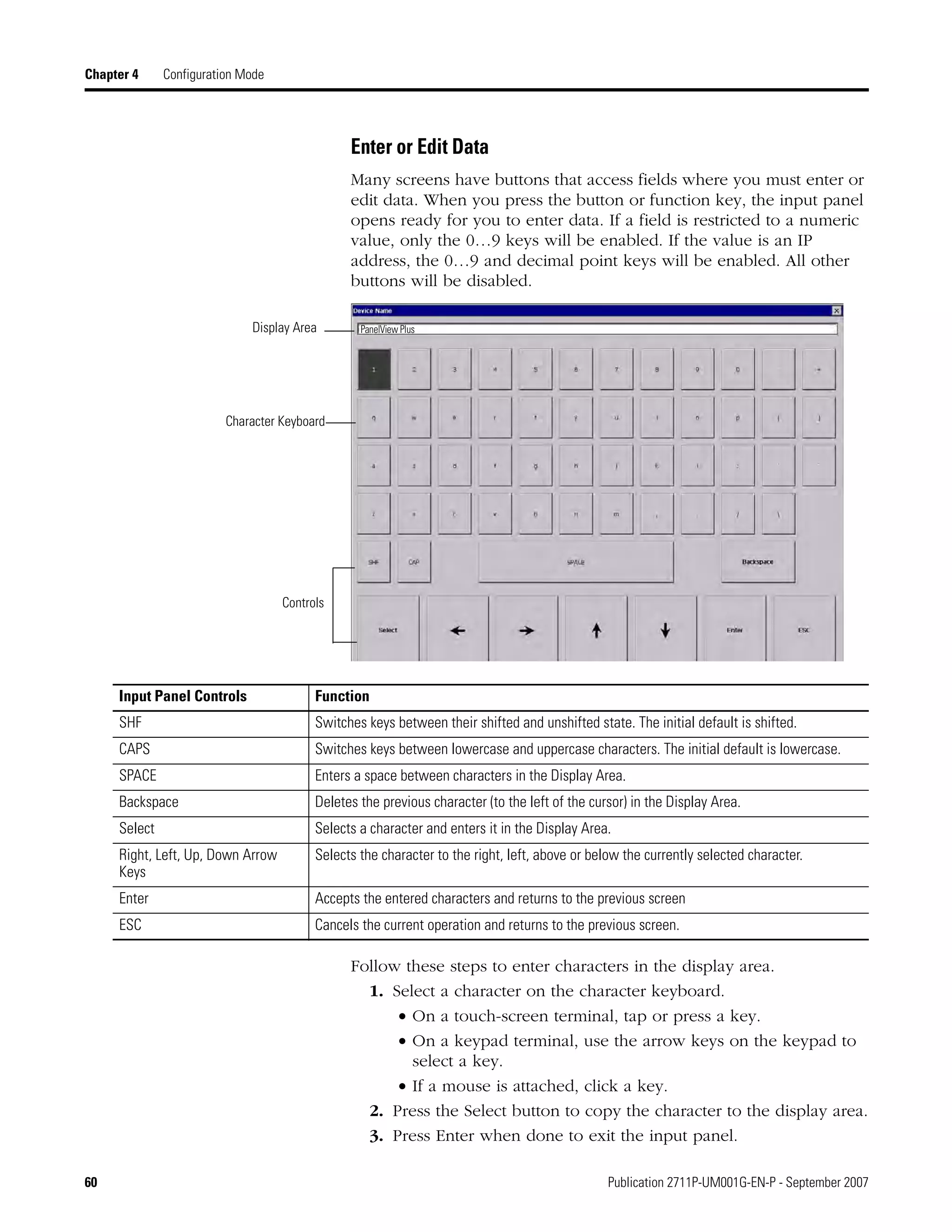
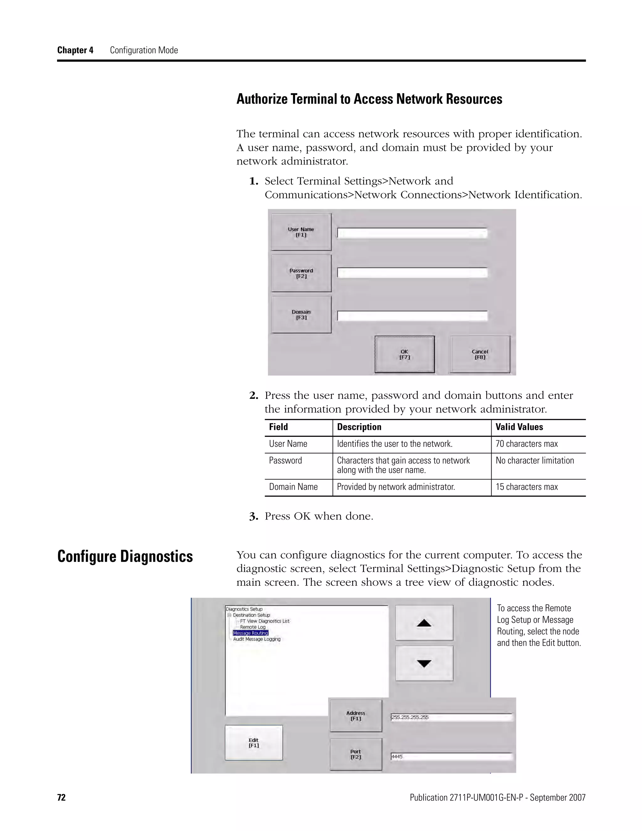
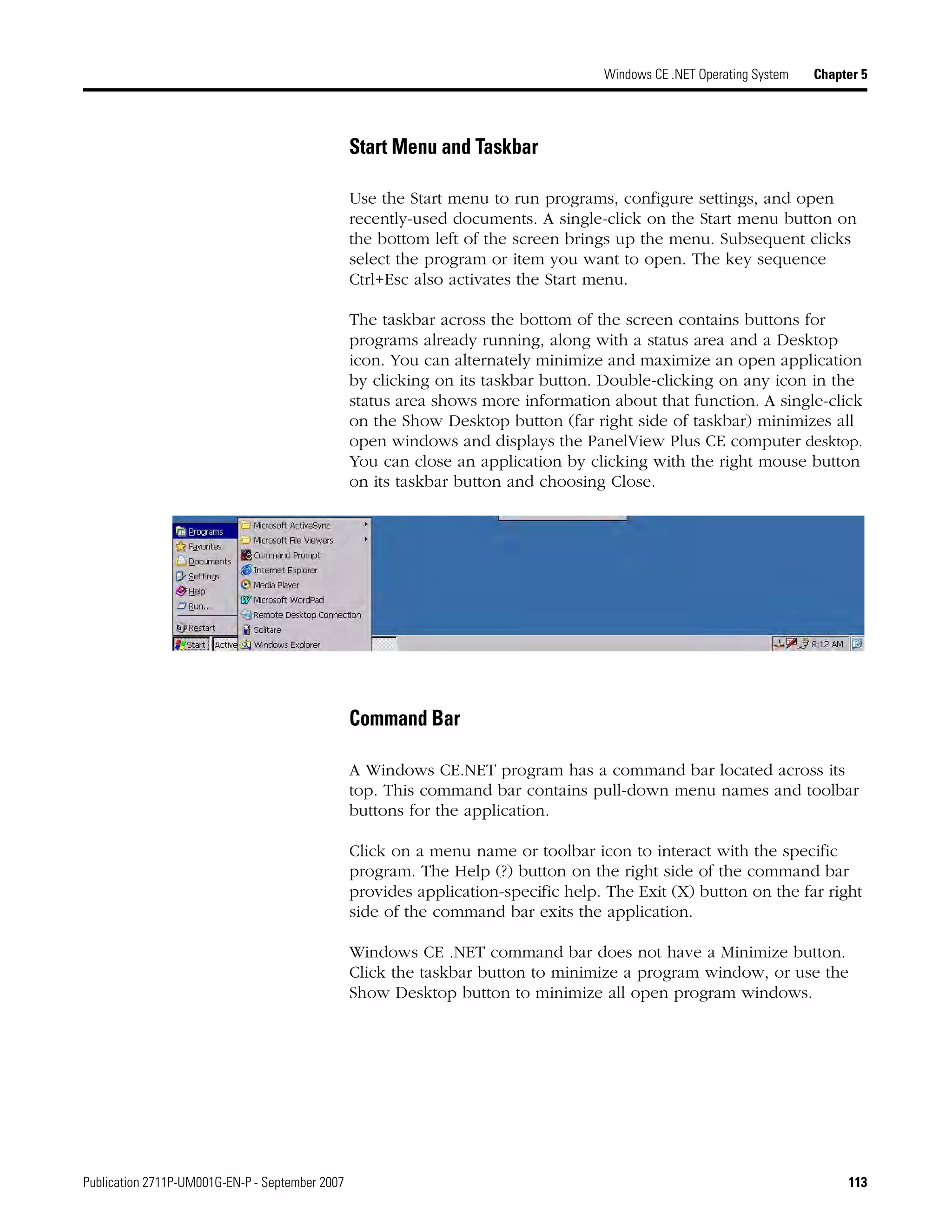
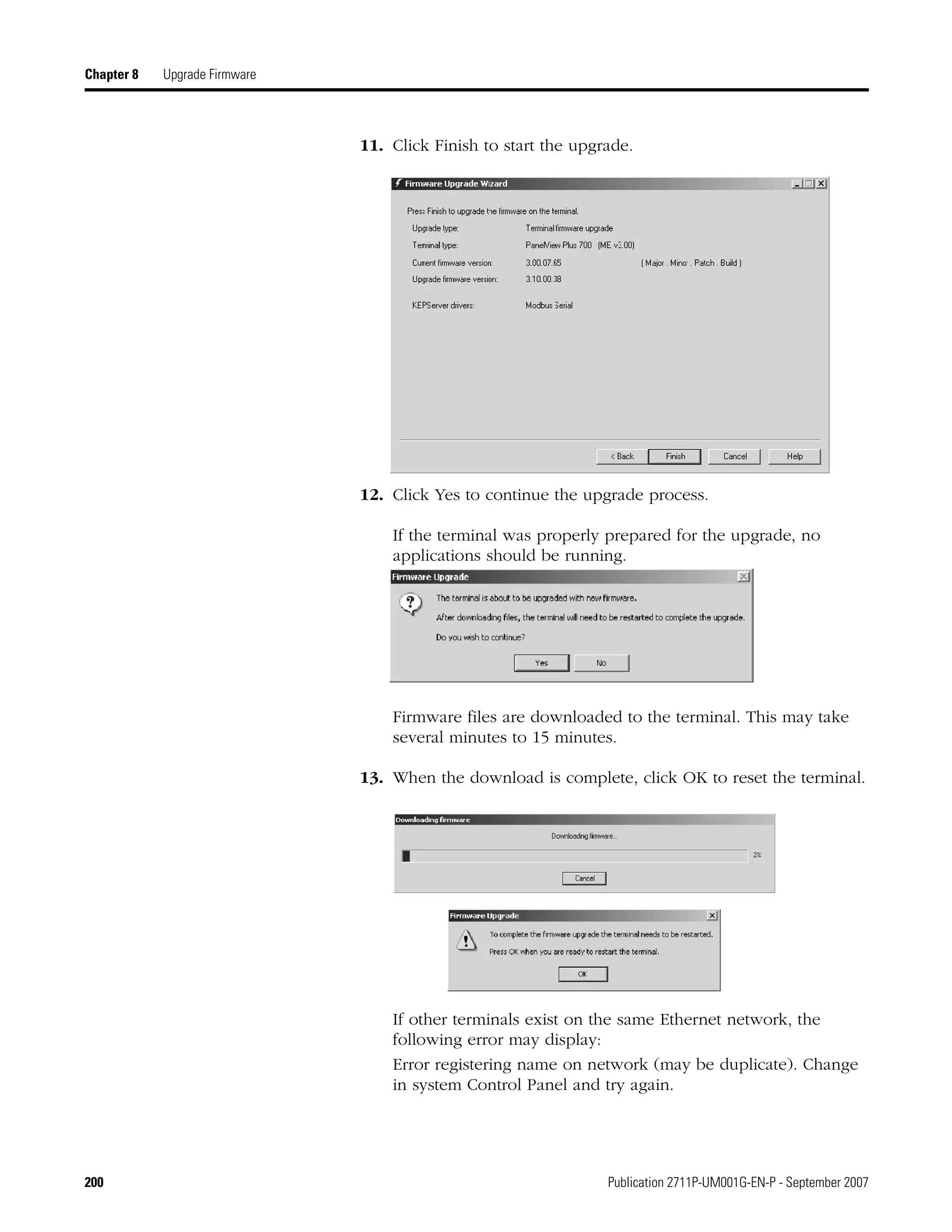
In addition to operation specific buttons, most screens have a
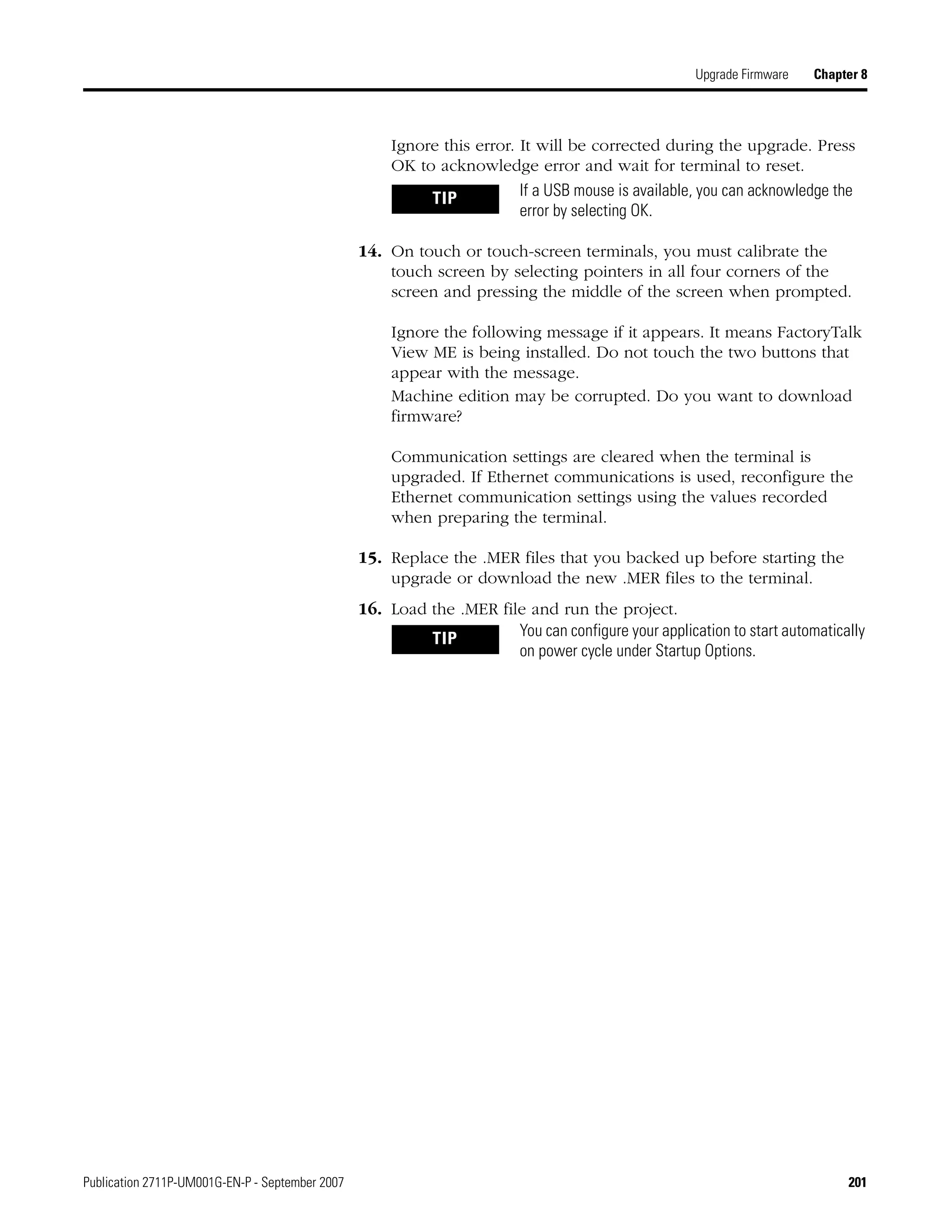
combination of these buttons.
Navigation Buttons Description
Returns to the previous screen.
Accepts modified values and returns to
previous screen.
Cancels the current operation without saving
any changes.
Moves highlight up or down a list.
Selects a highlighted screen or item from a list.
Close
[F8]
OK
[F7]
Cancel
[F8]](https://image.slidesharecdn.com/panelviewplusmanual-150321055544-conversion-gate01/75/Panelviewplusmanual-59-2048.jpg)
![Publication 2711P-UM001G-EN-P - September 2007 81
Configuration Mode Chapter 4
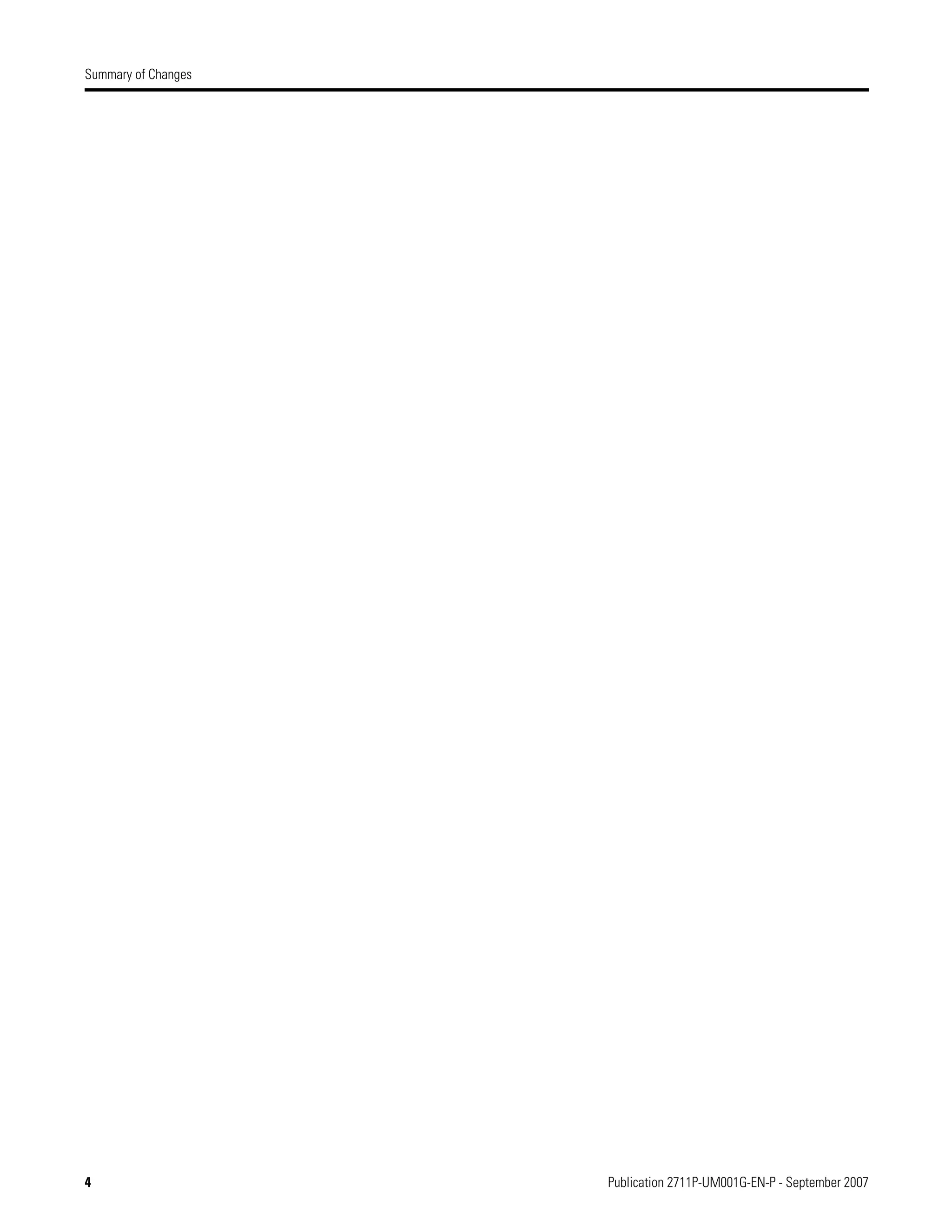
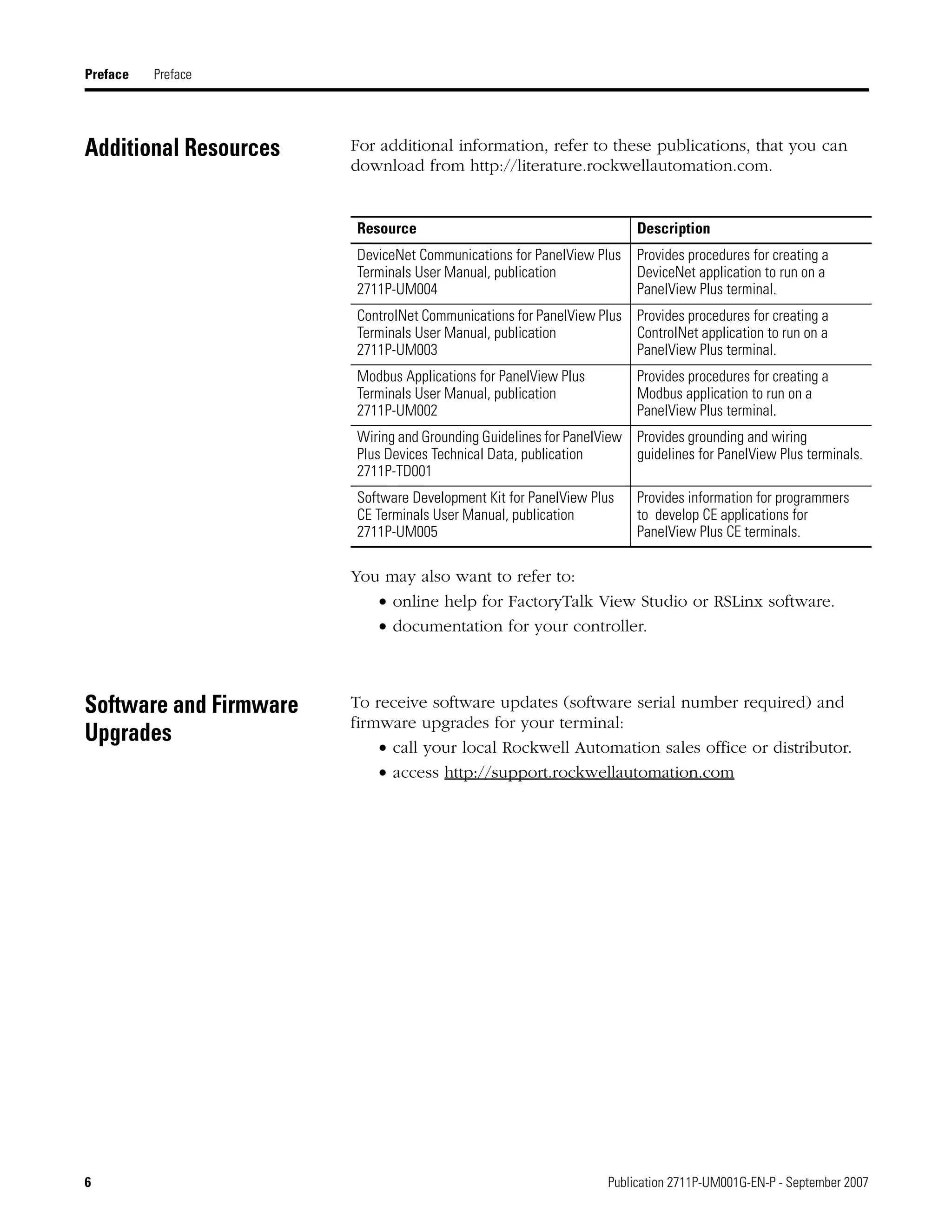
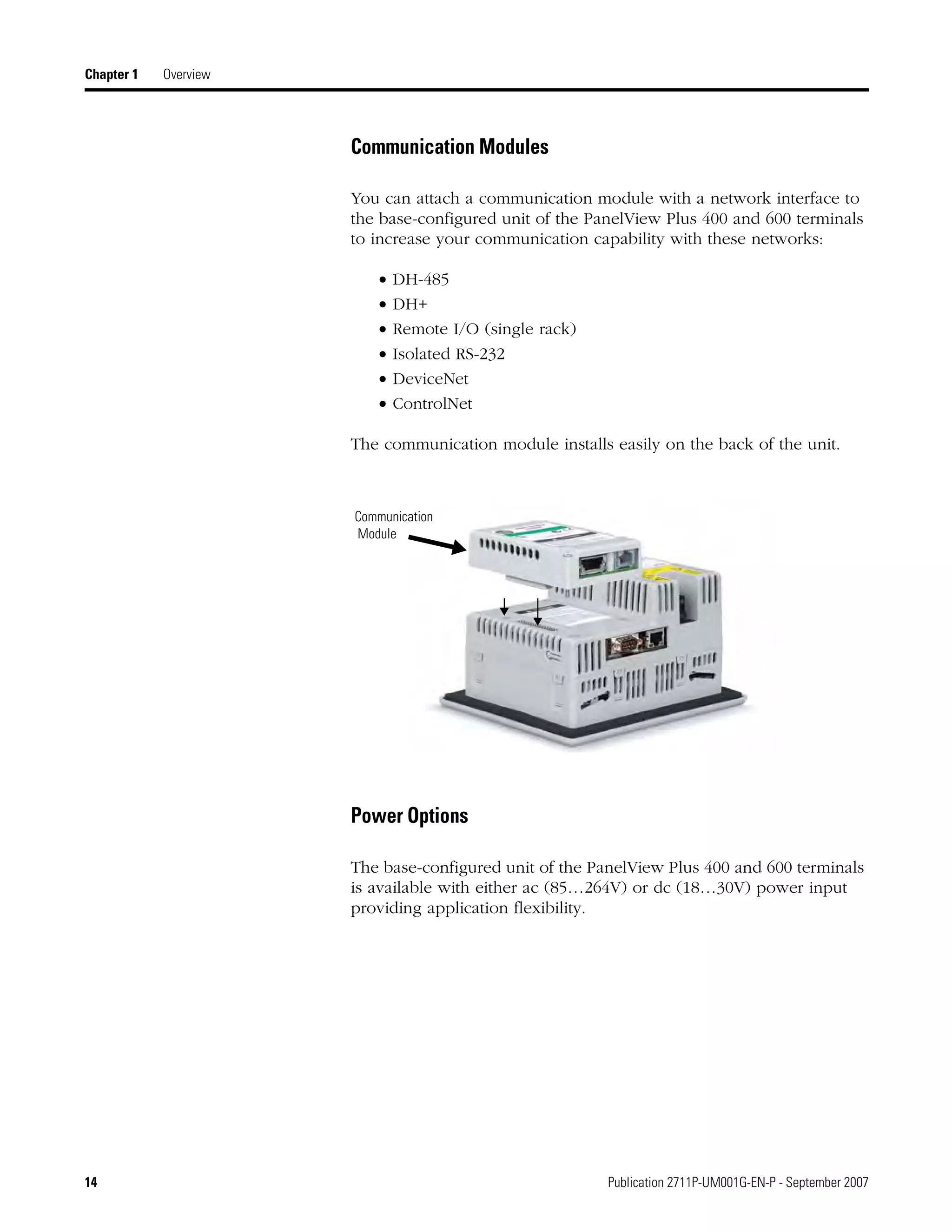
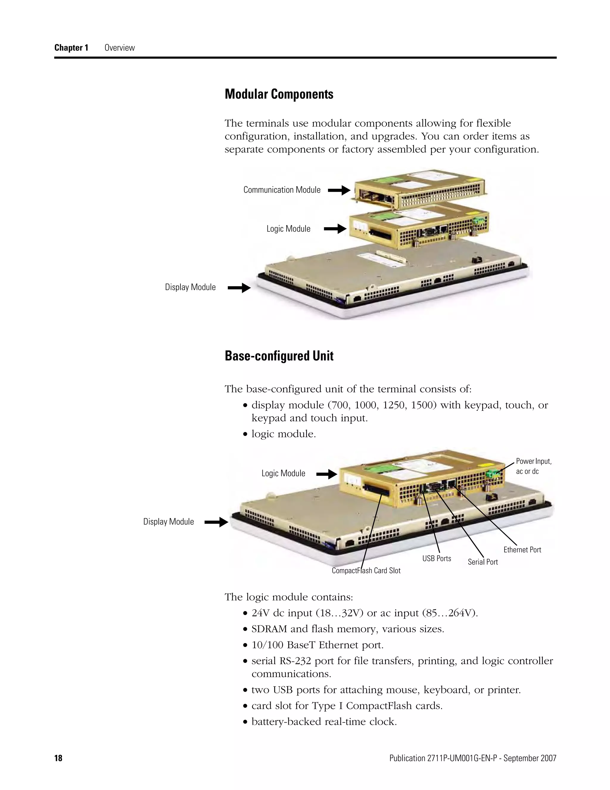
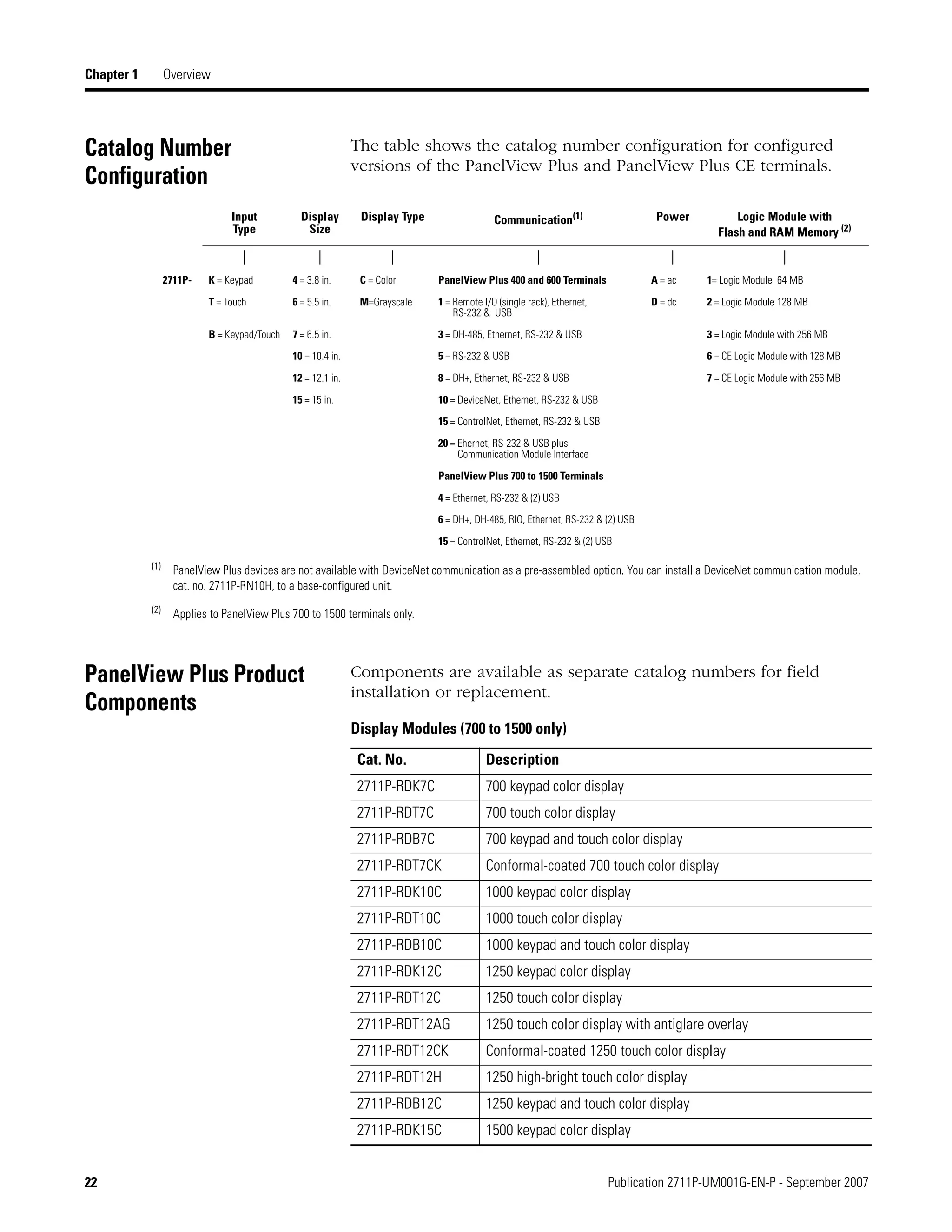
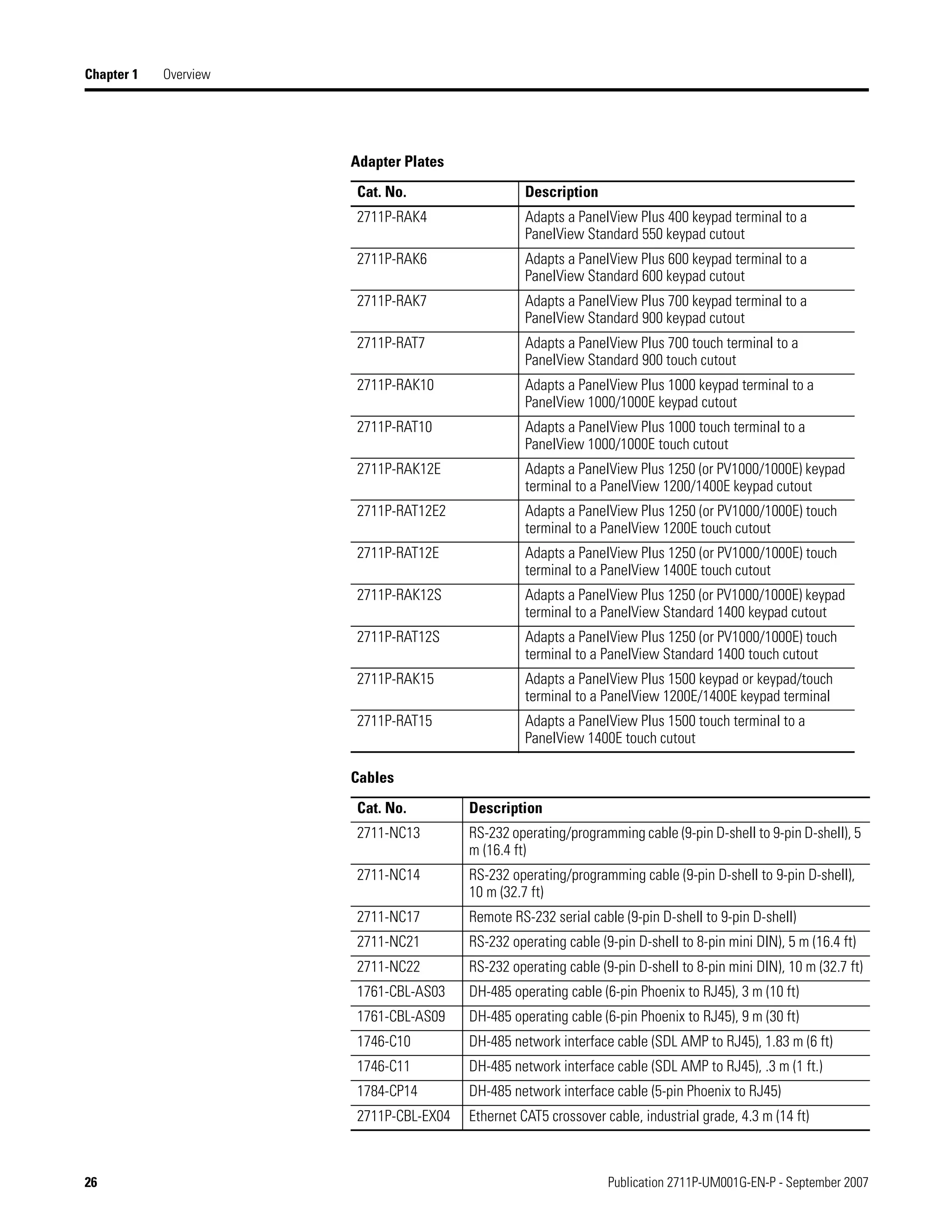
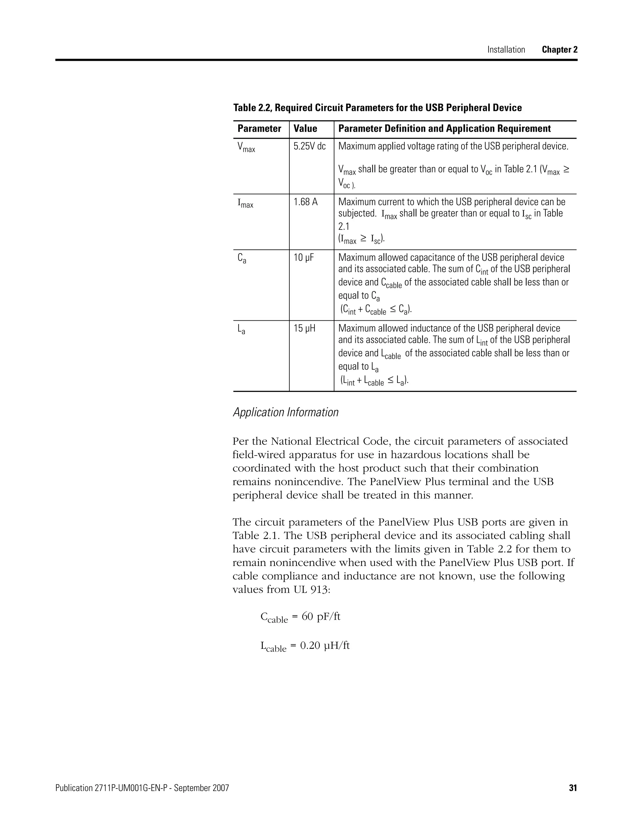
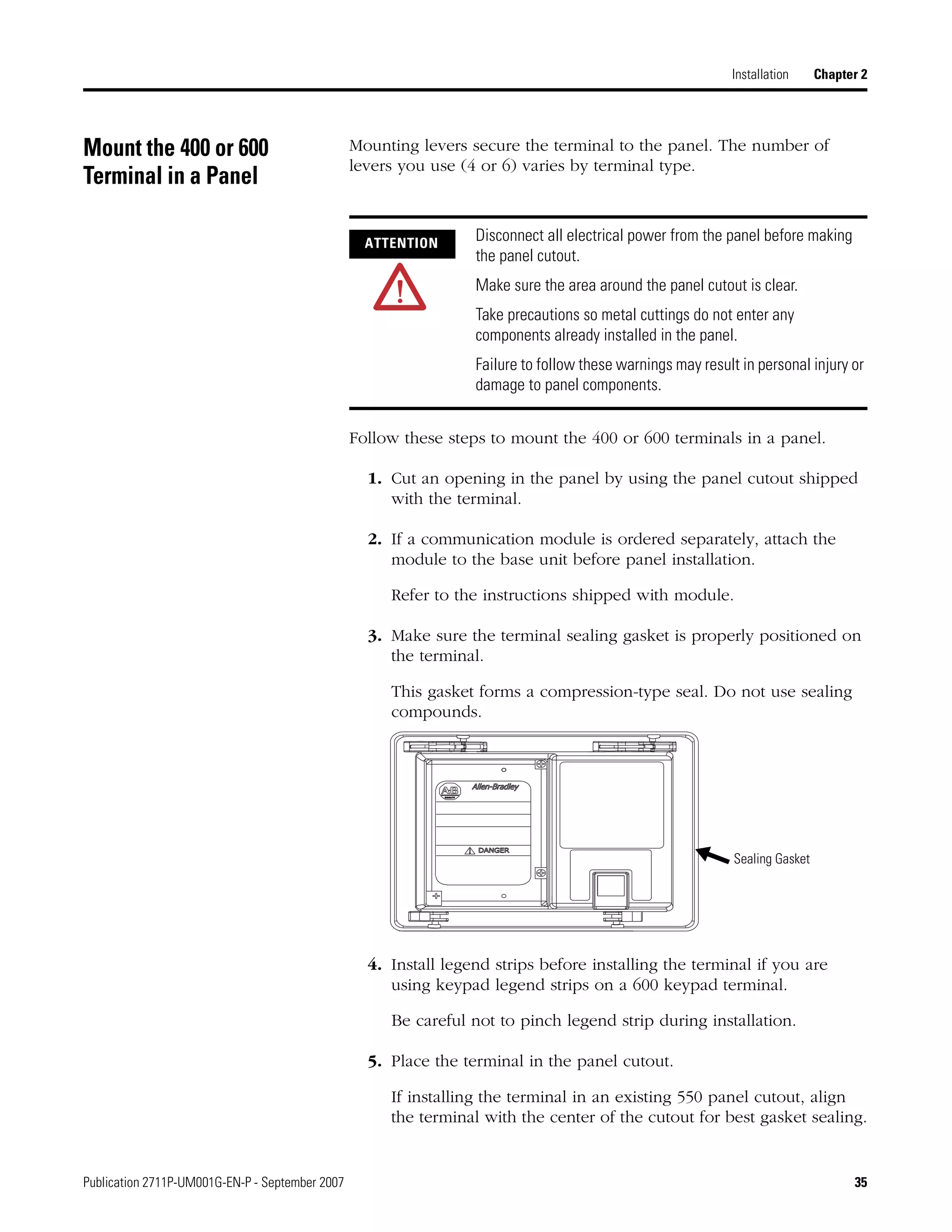
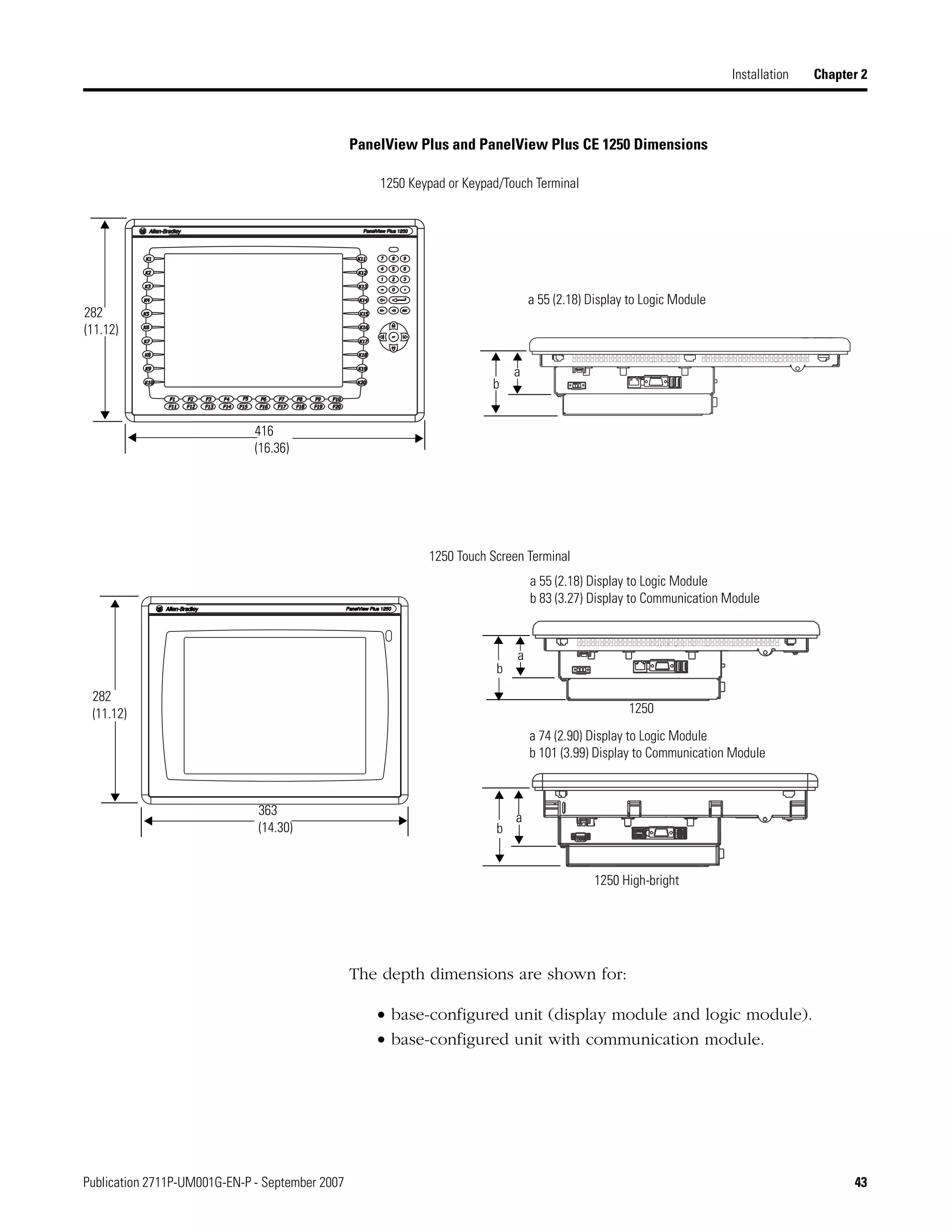
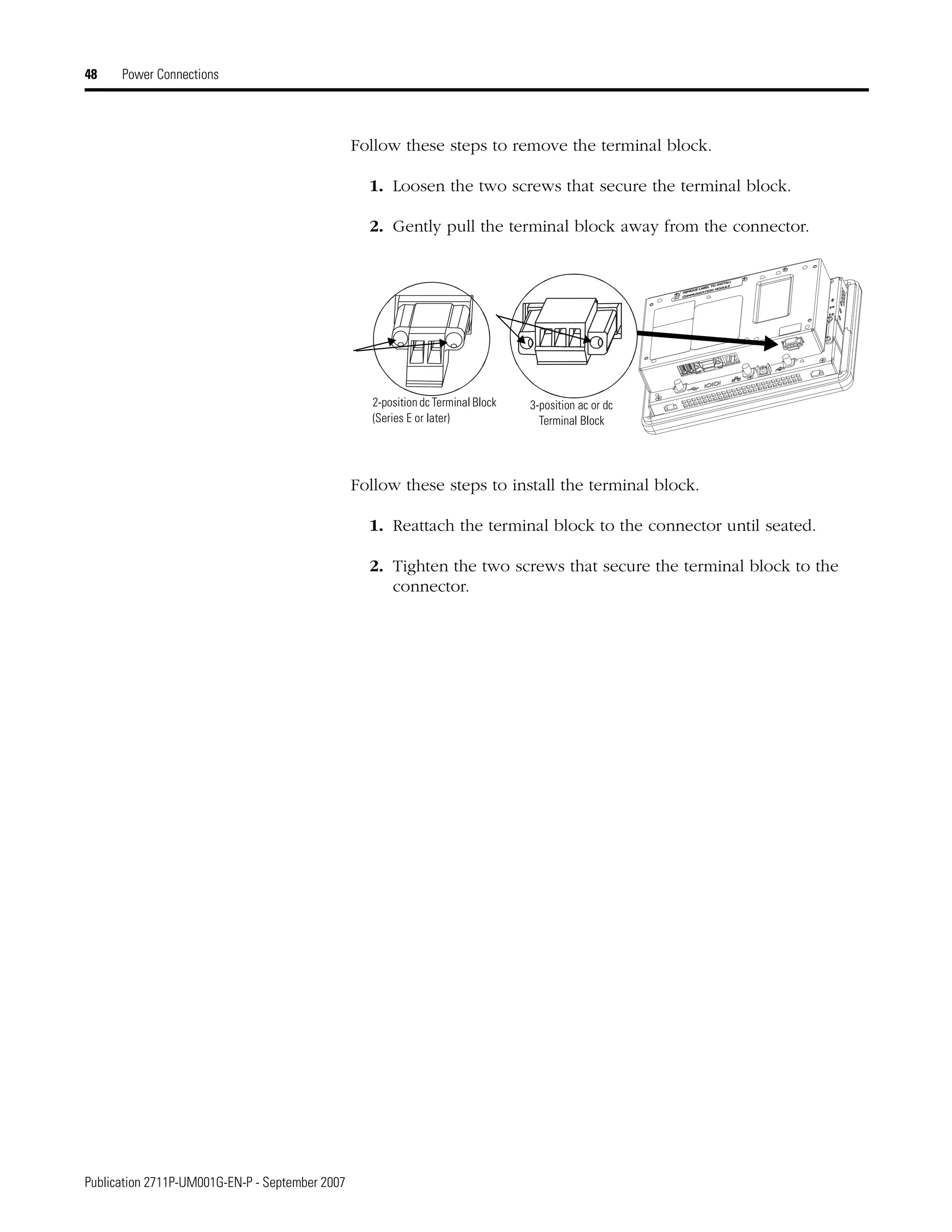
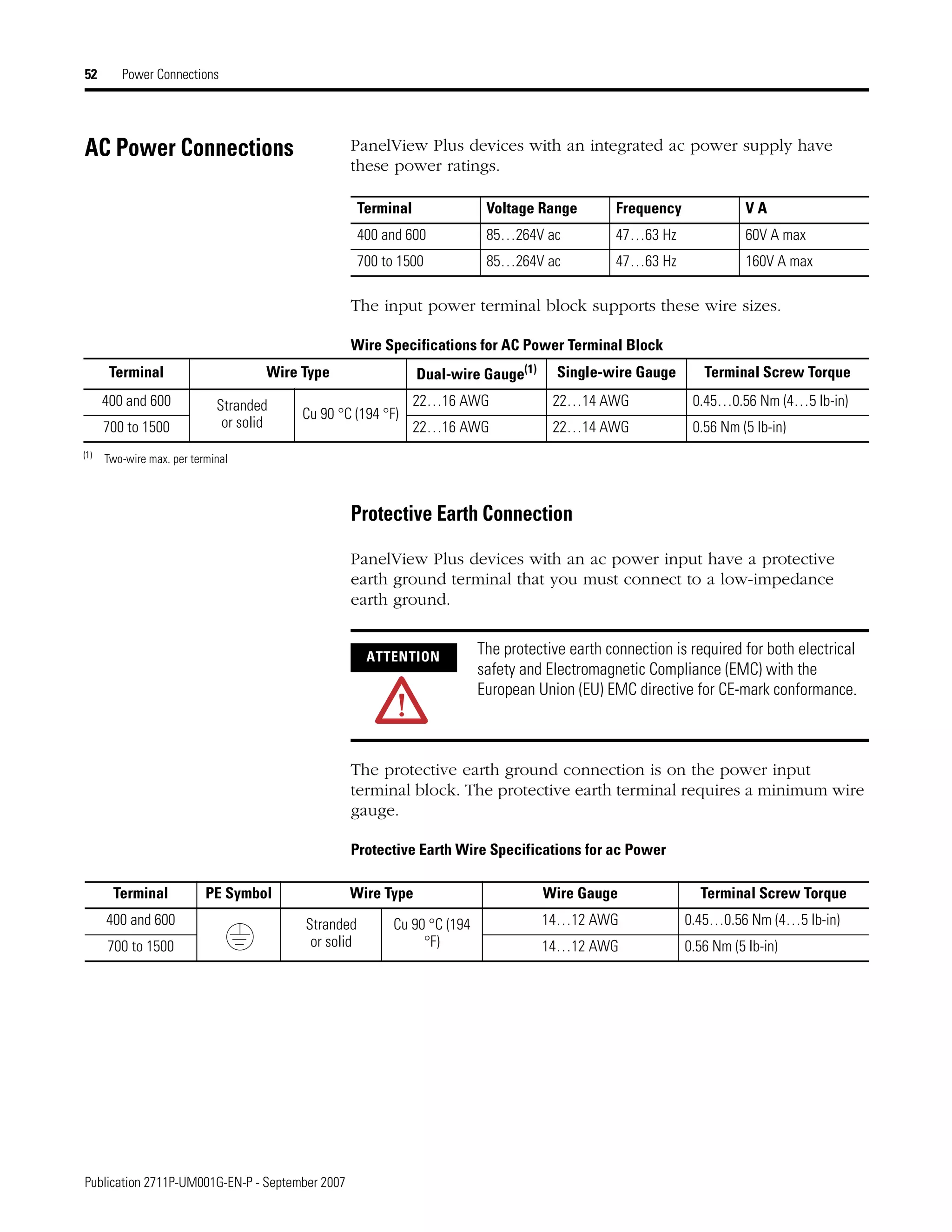
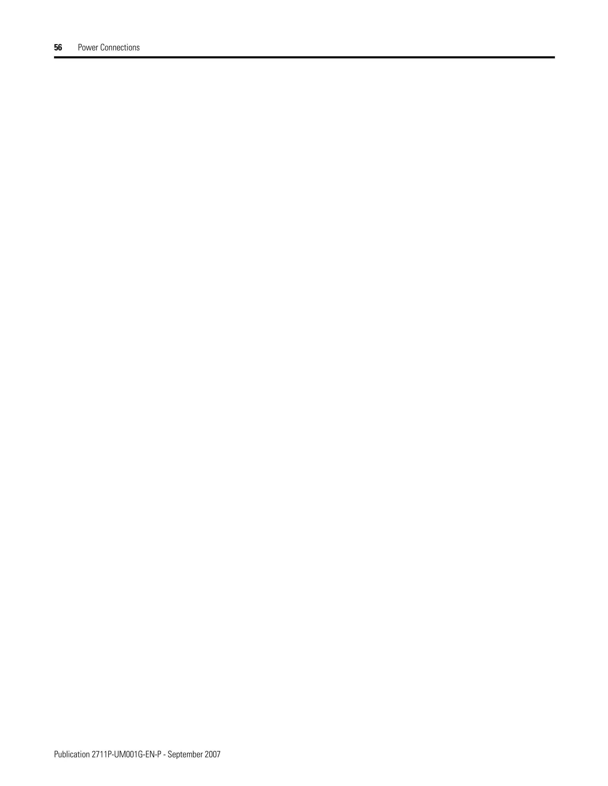
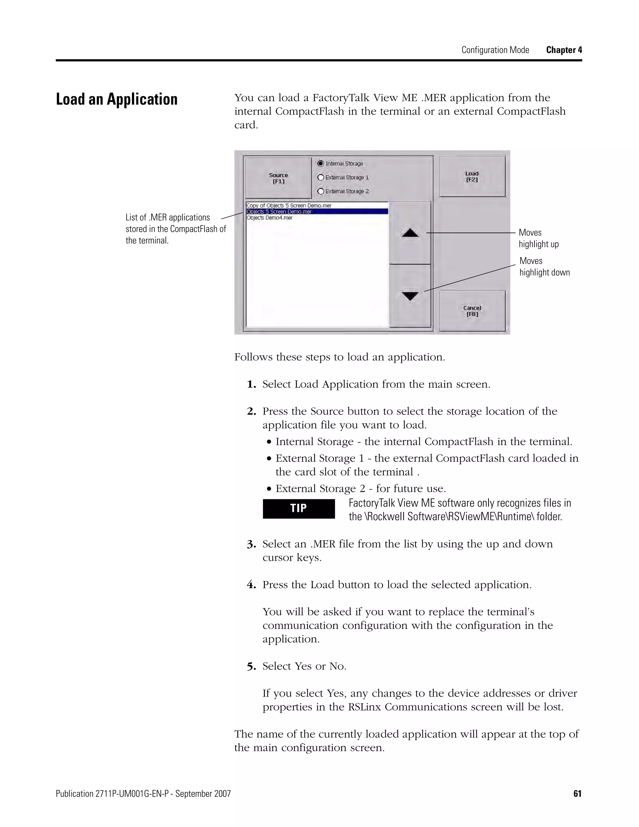
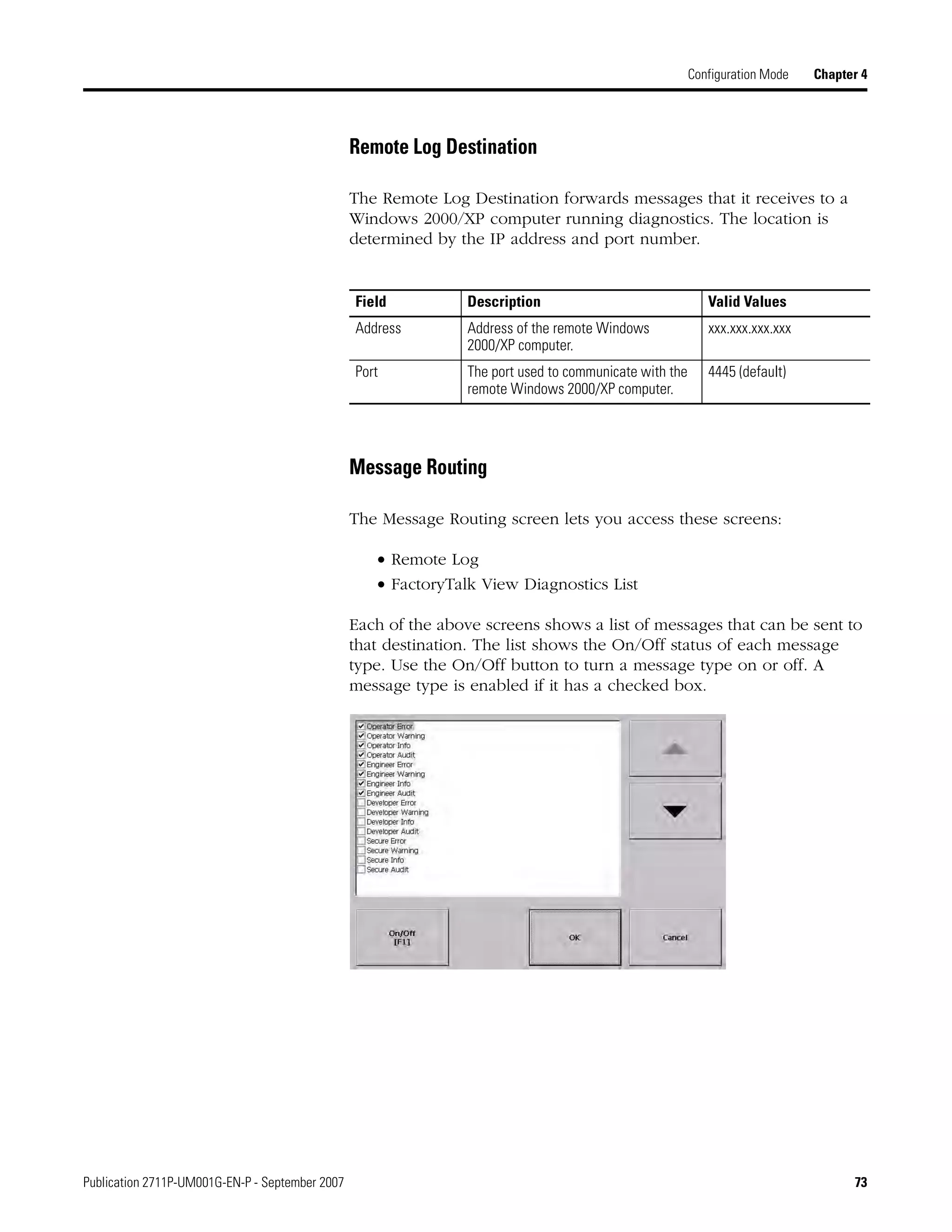
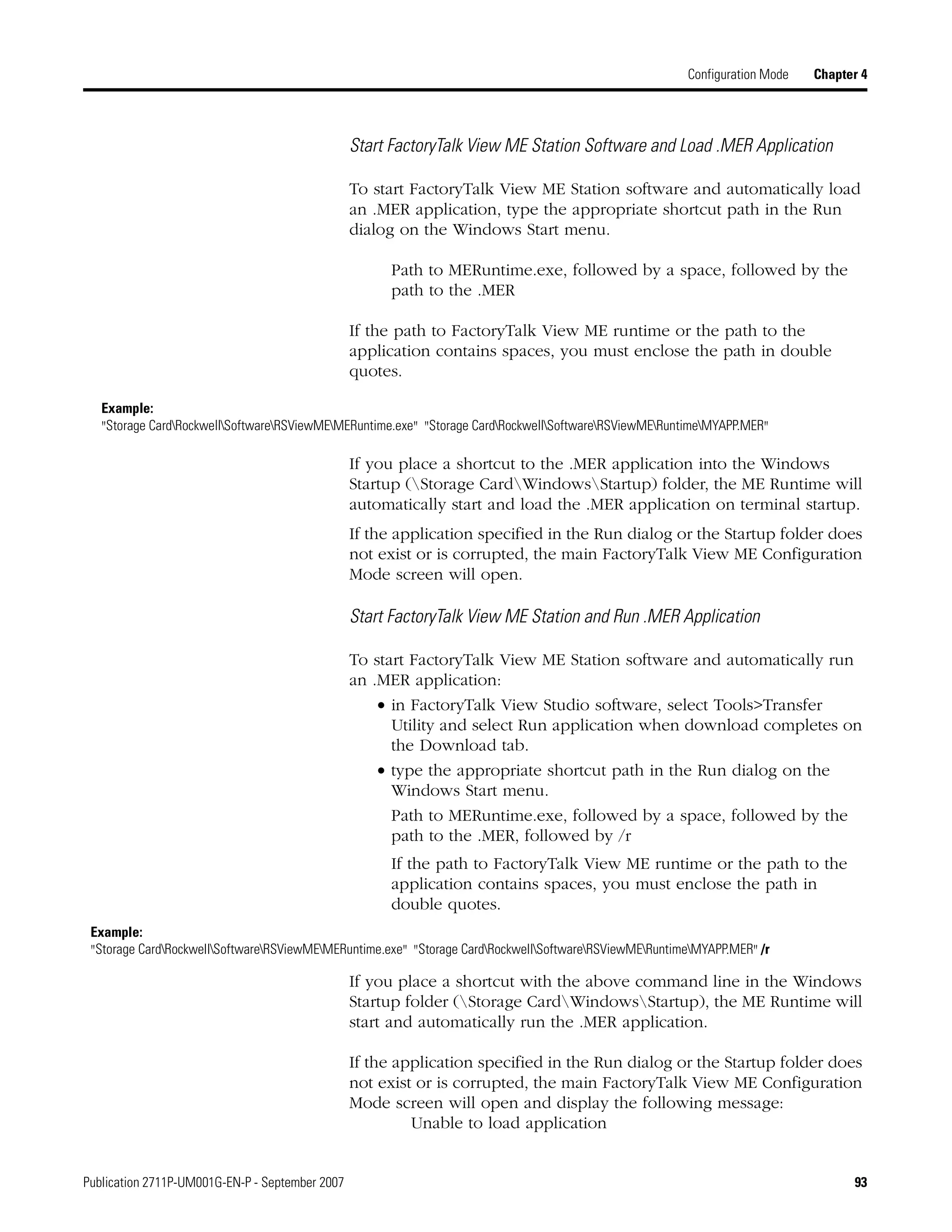
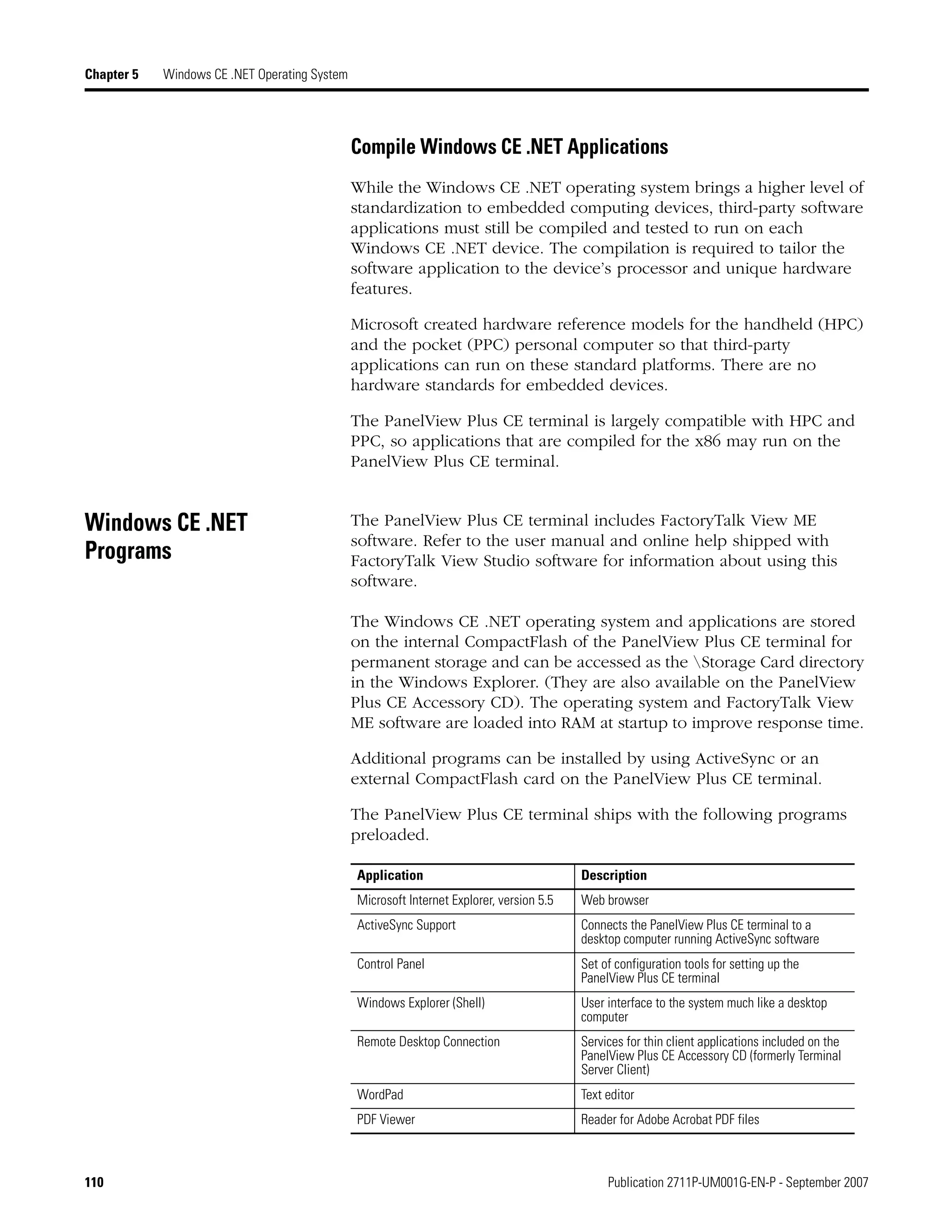
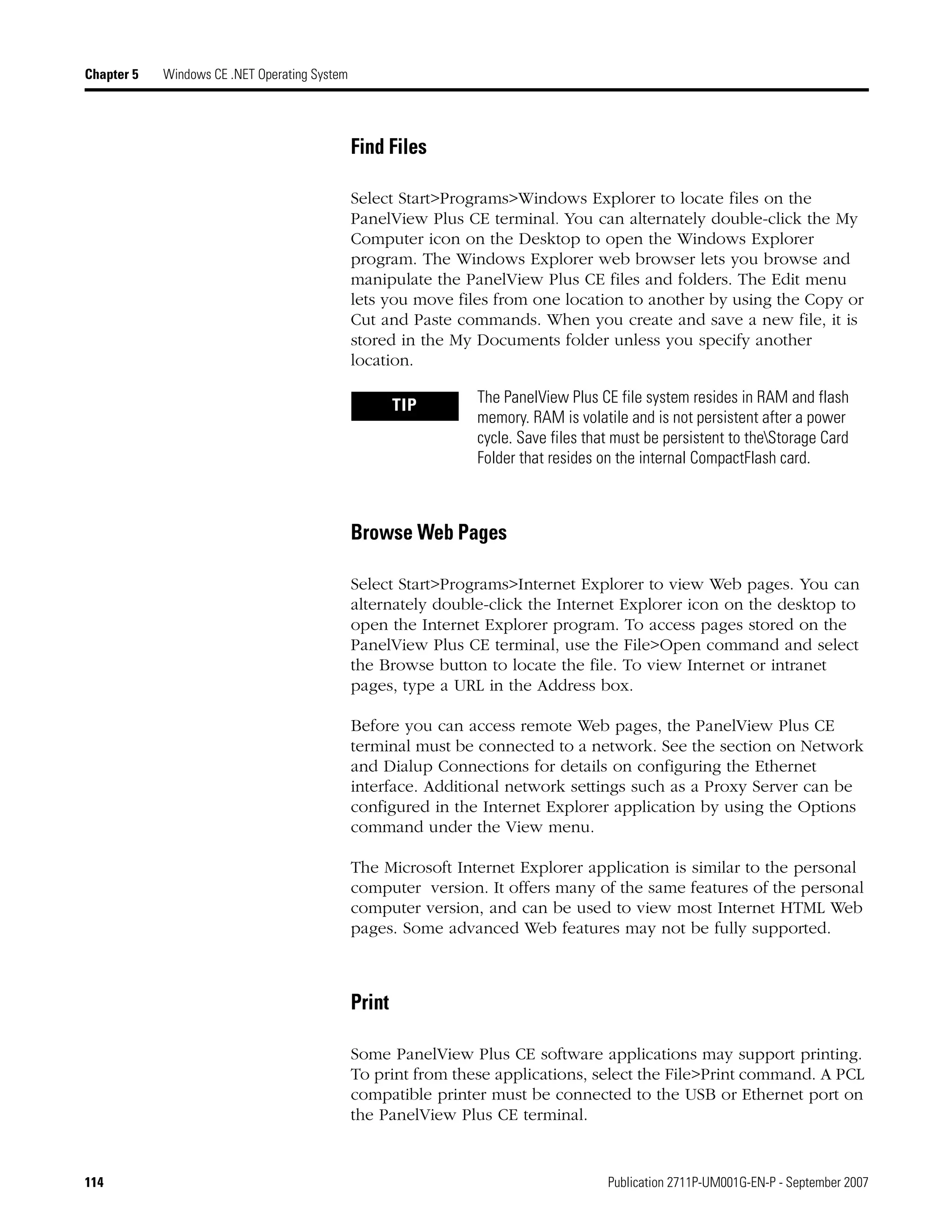
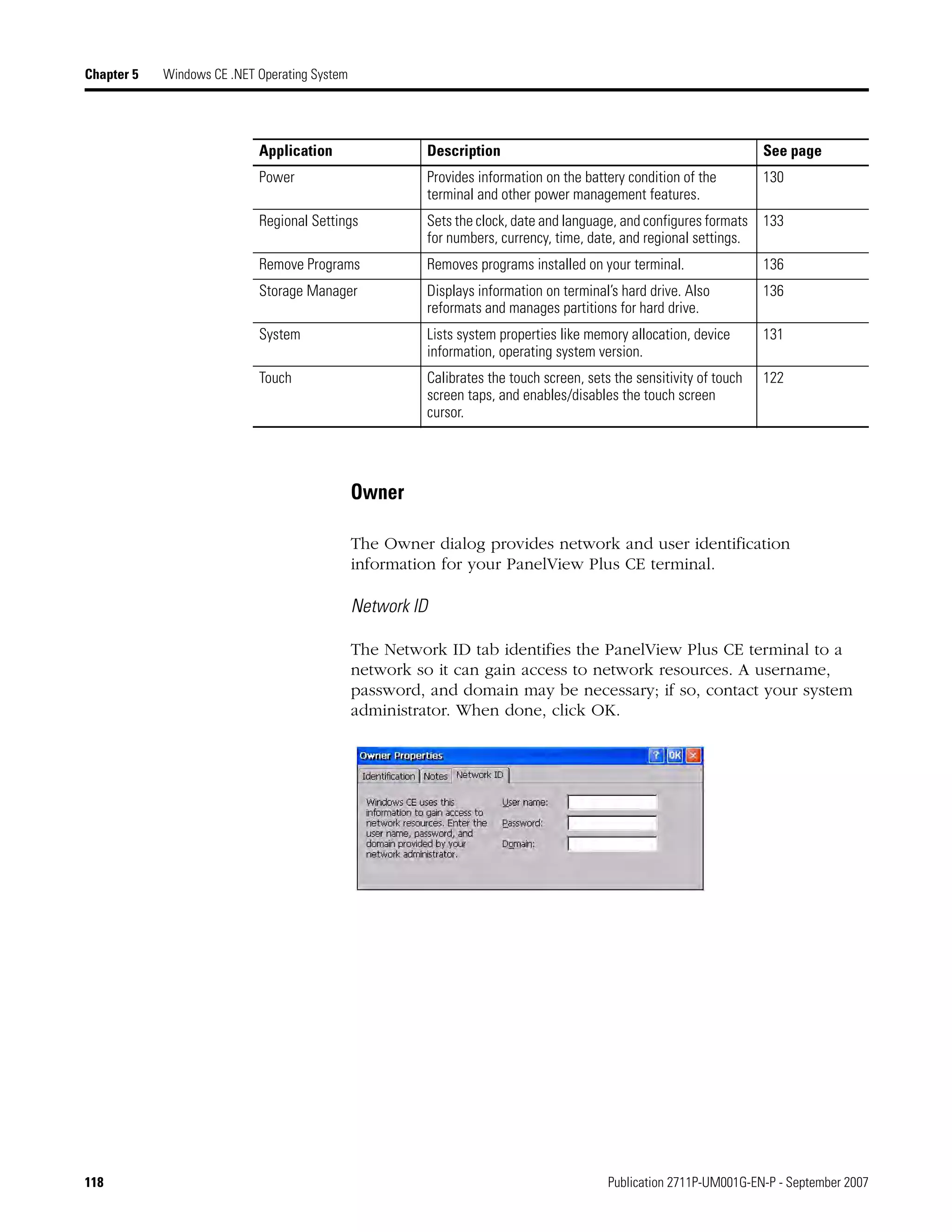
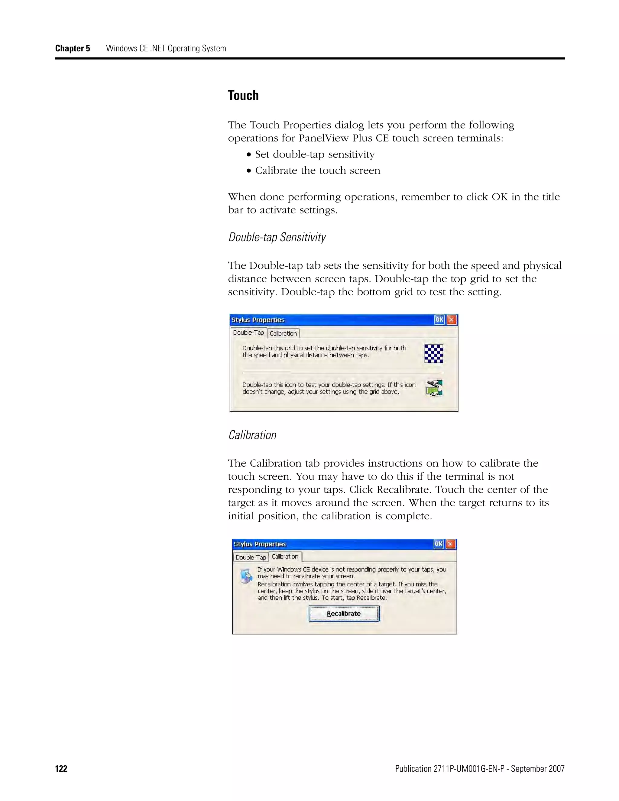
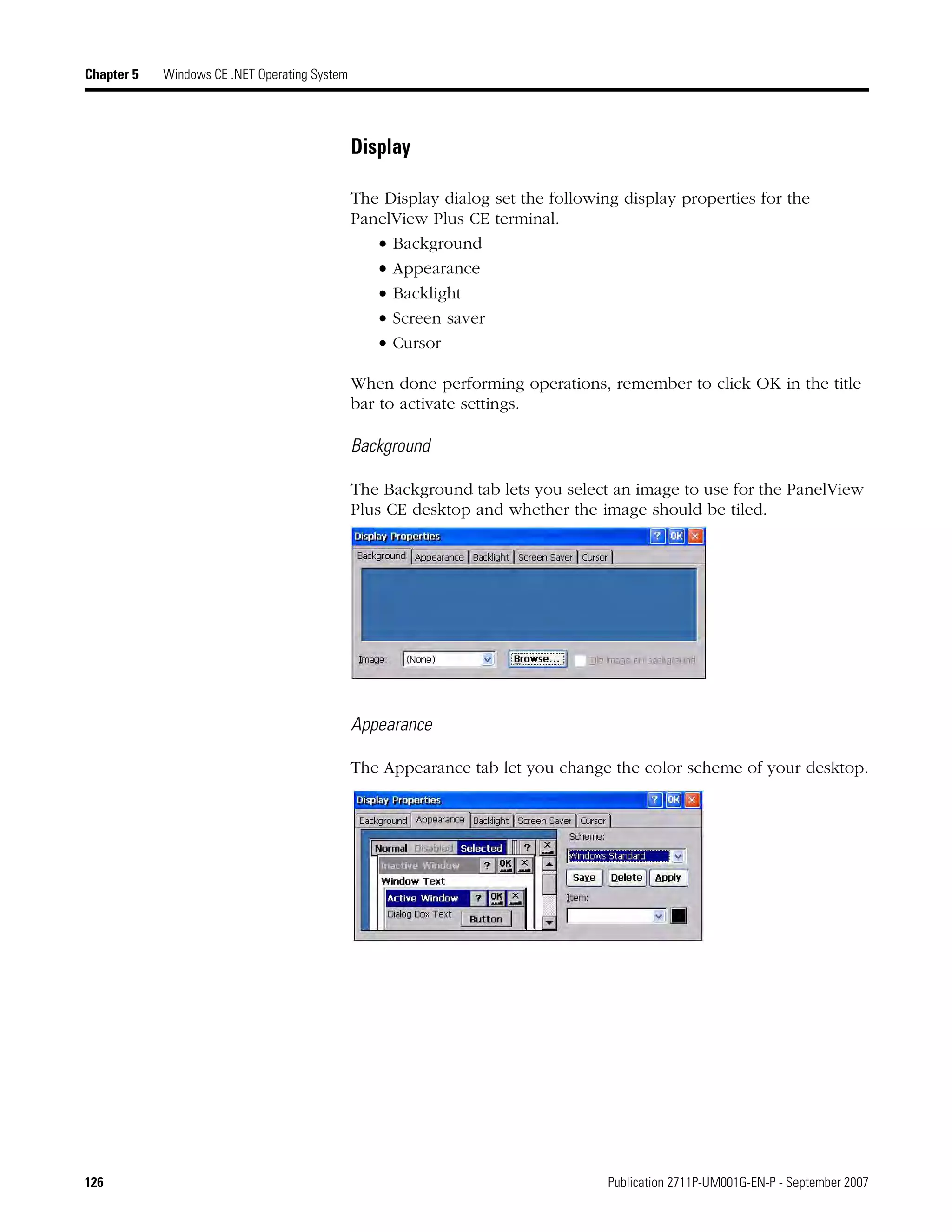
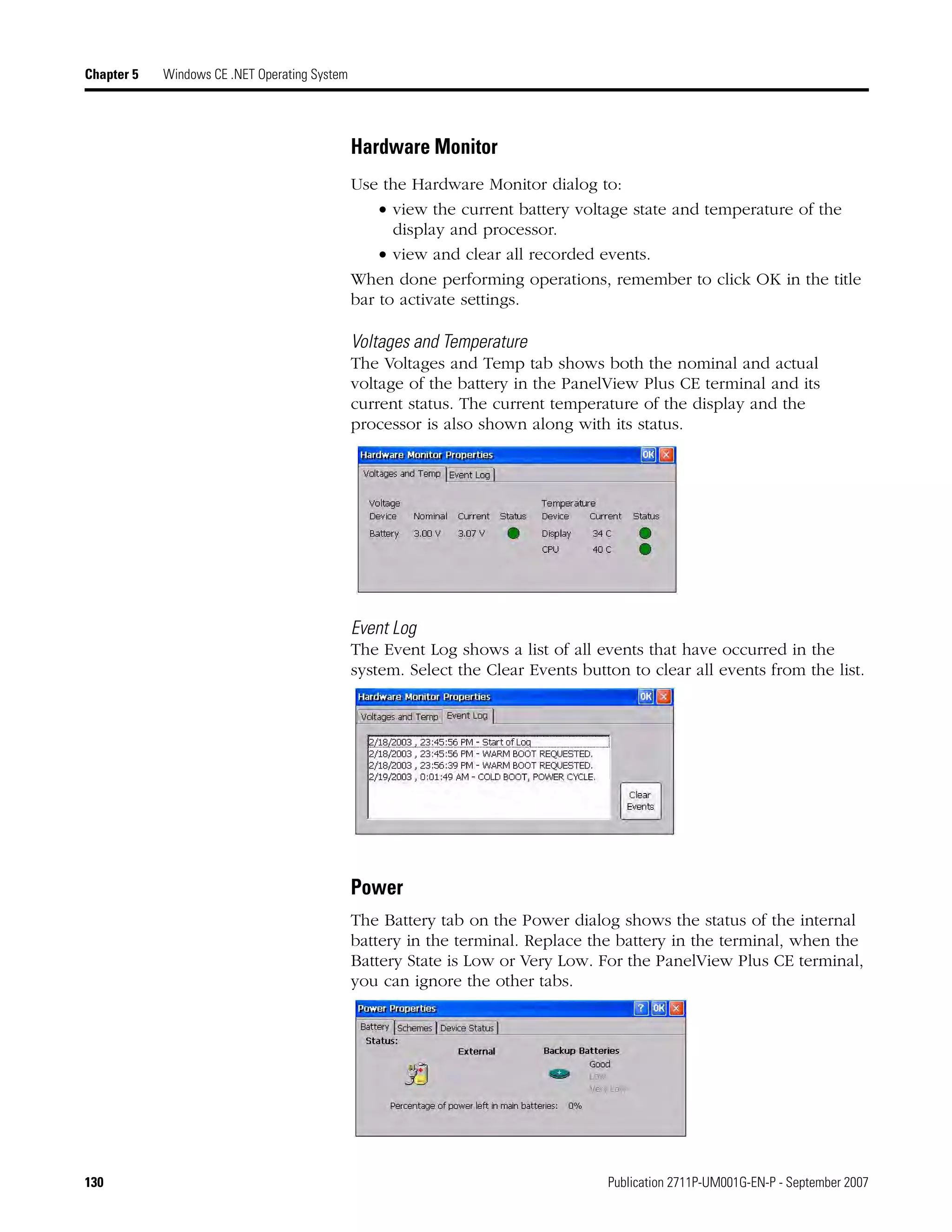
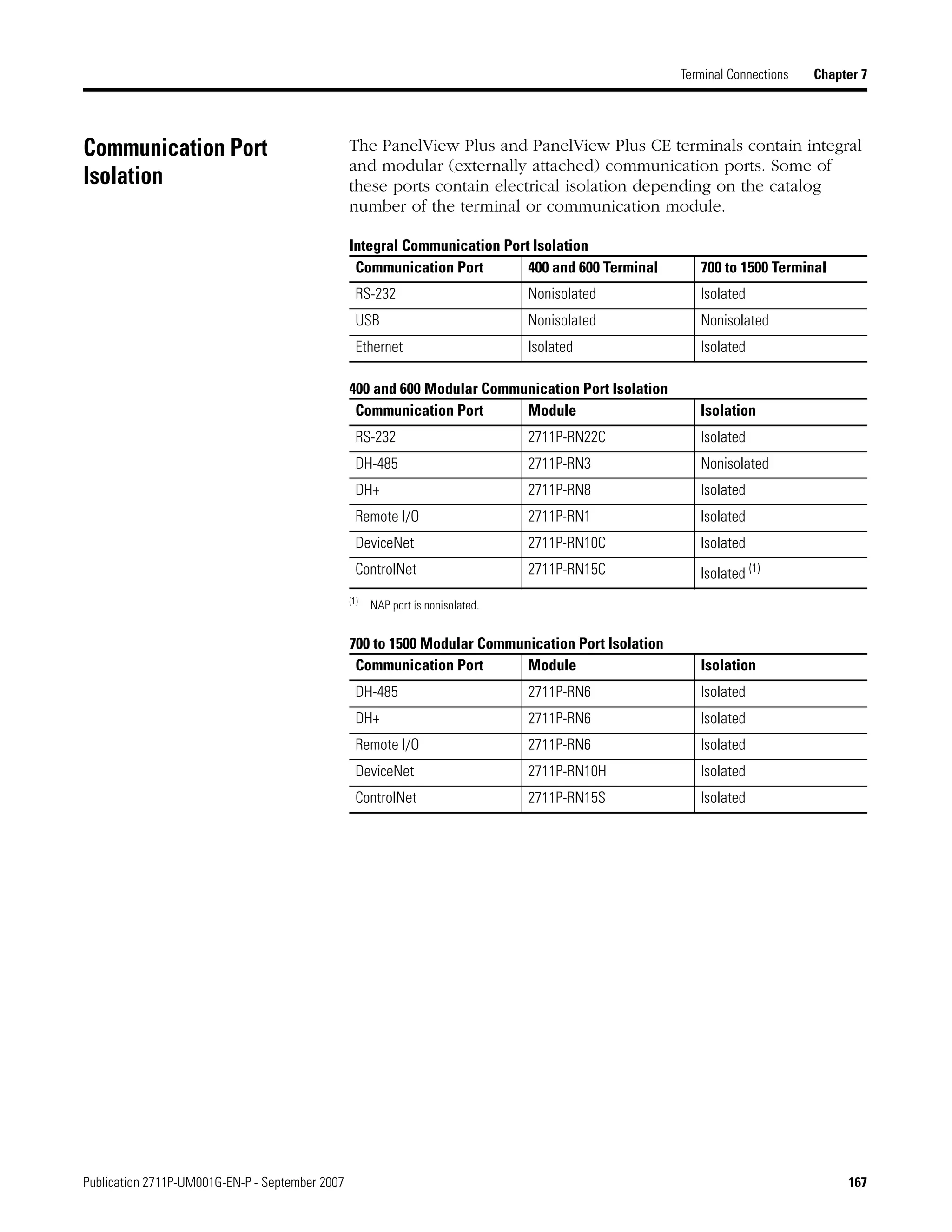
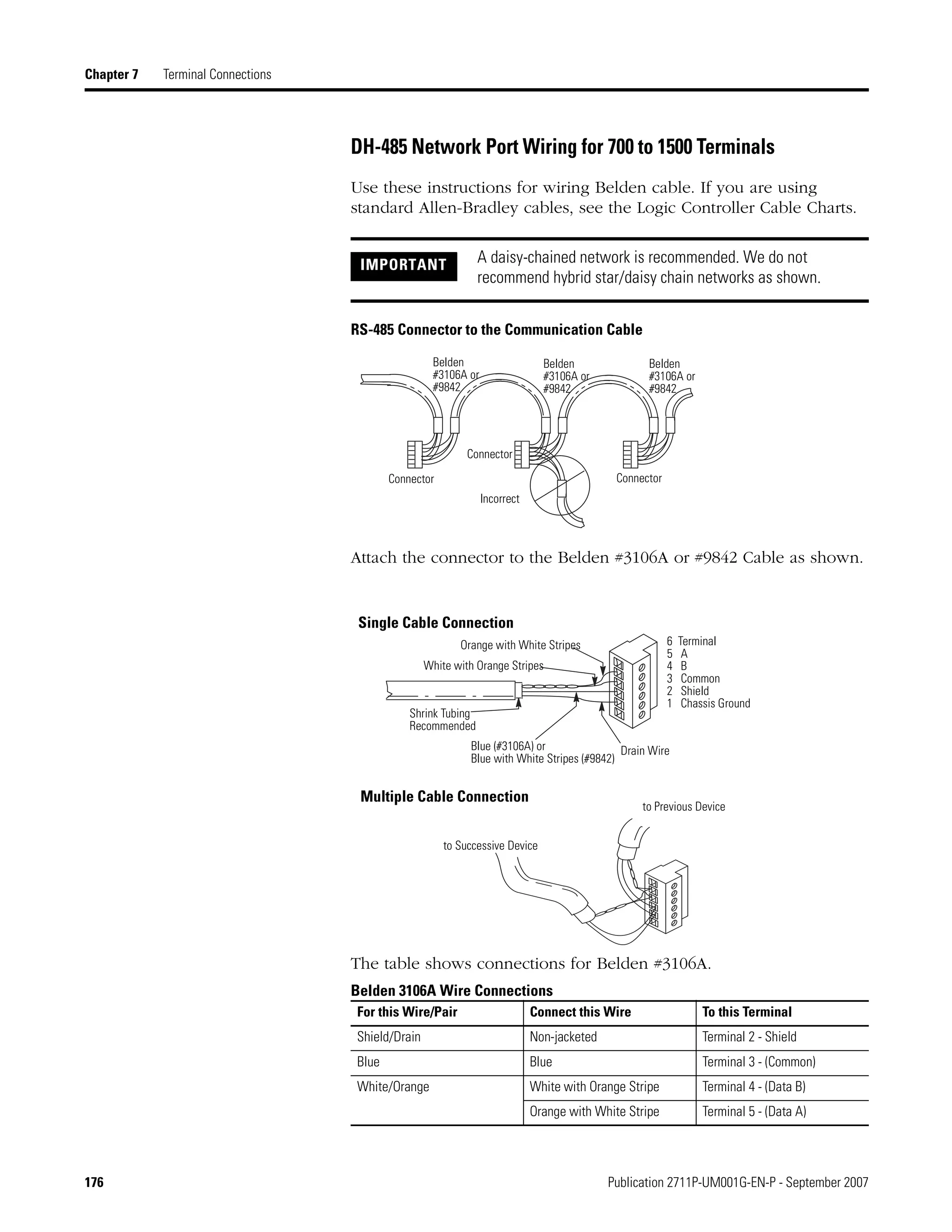
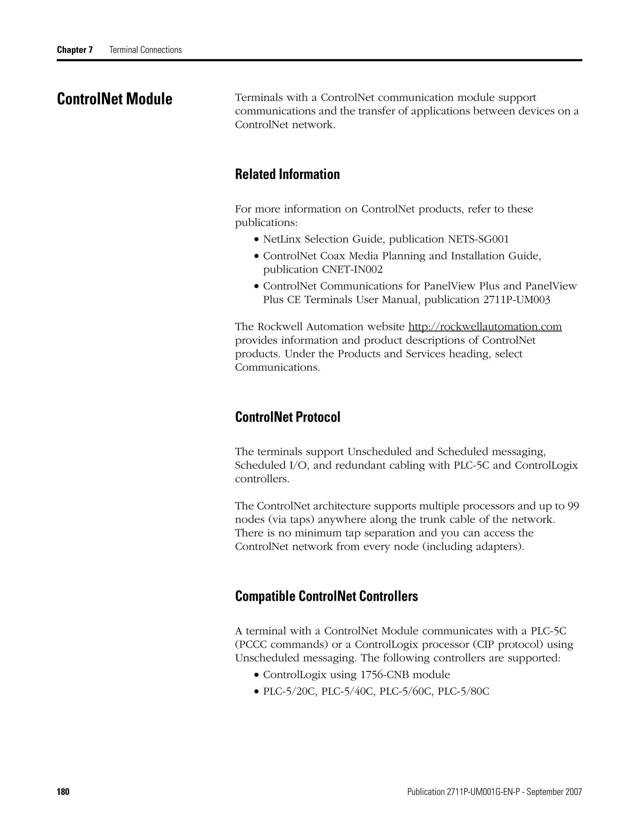
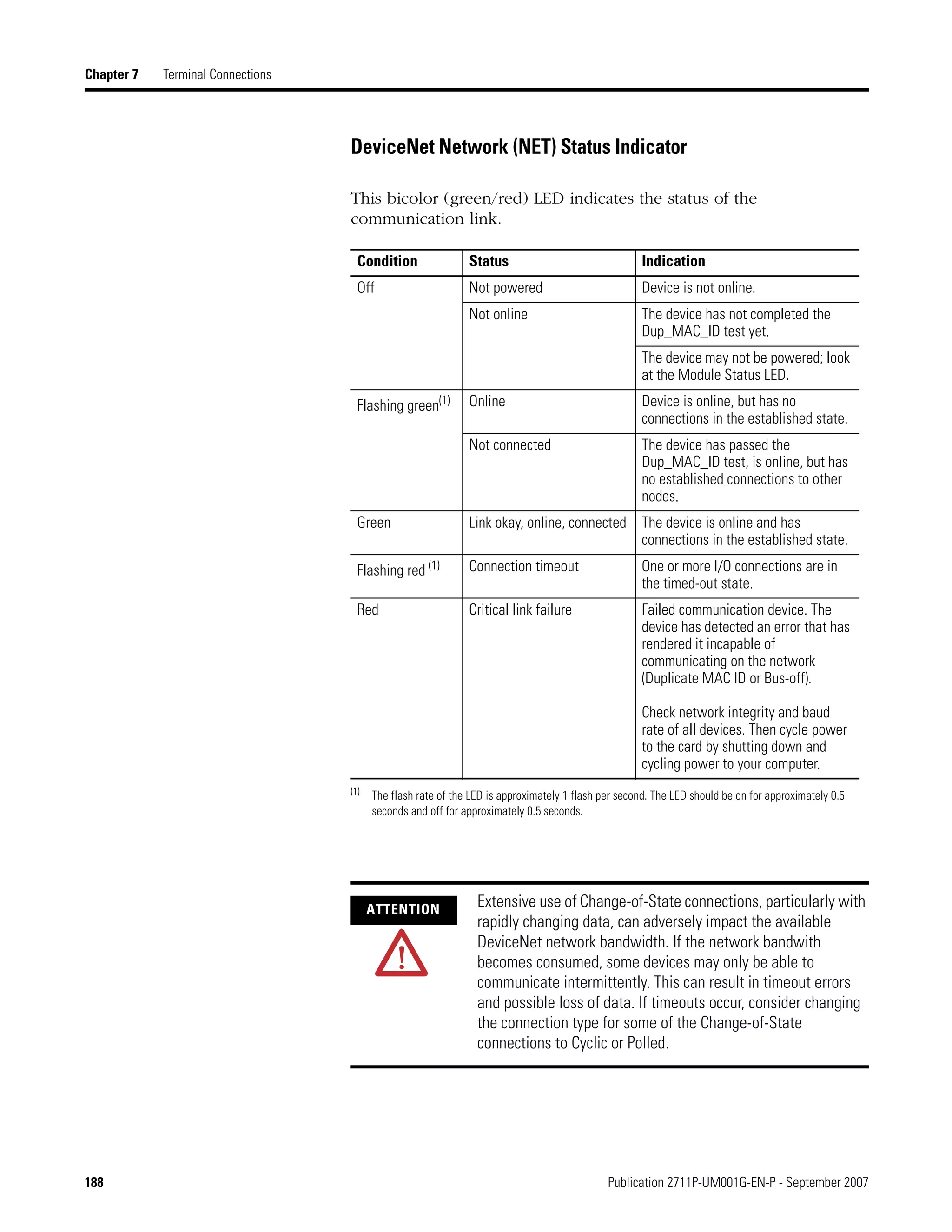
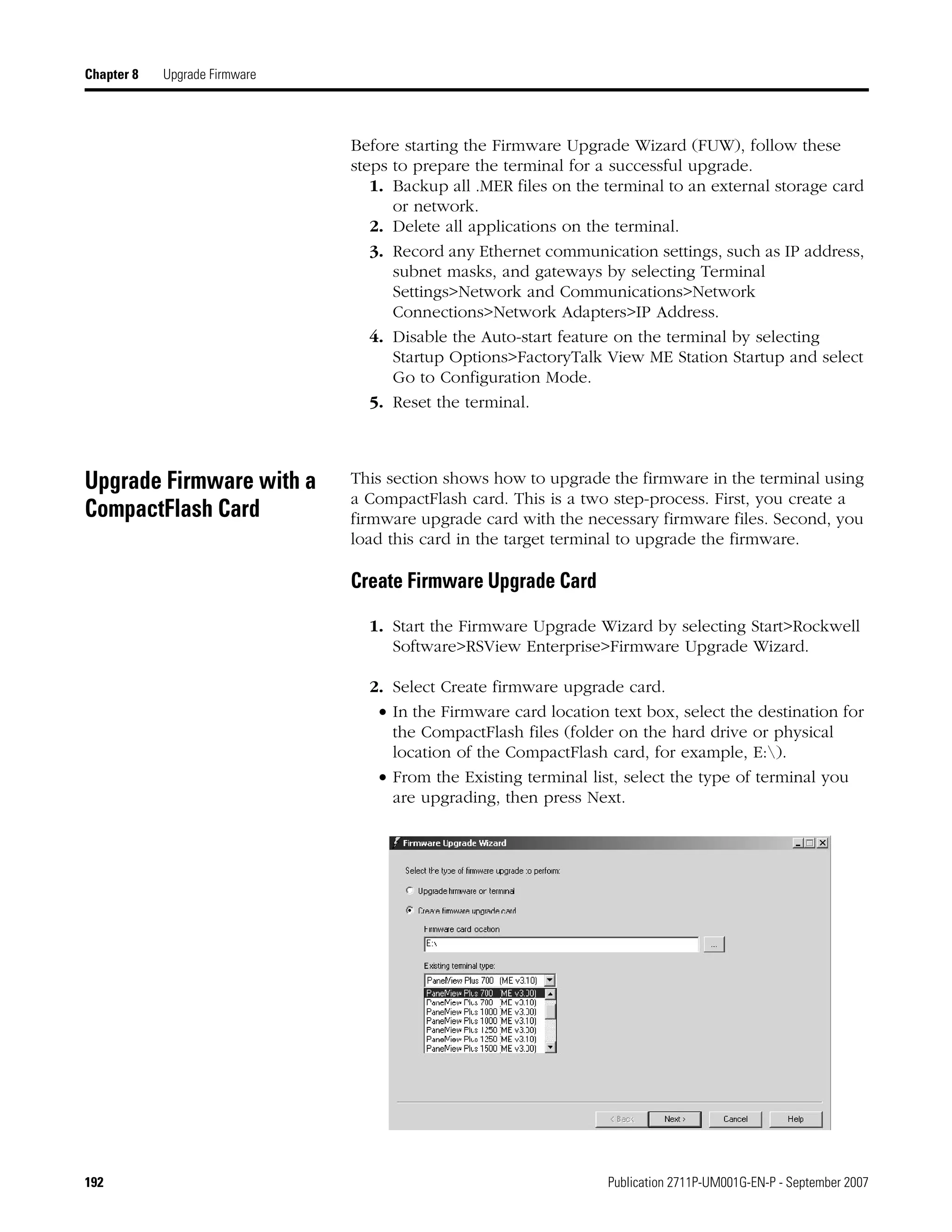
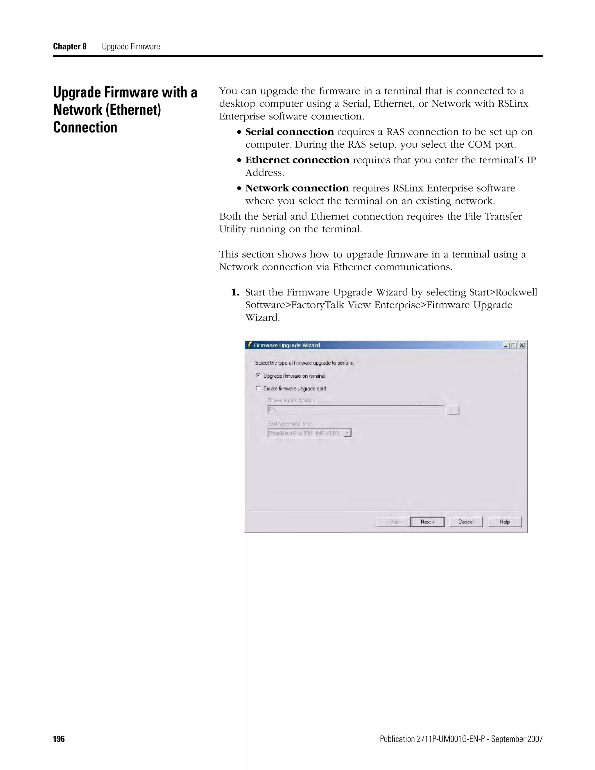
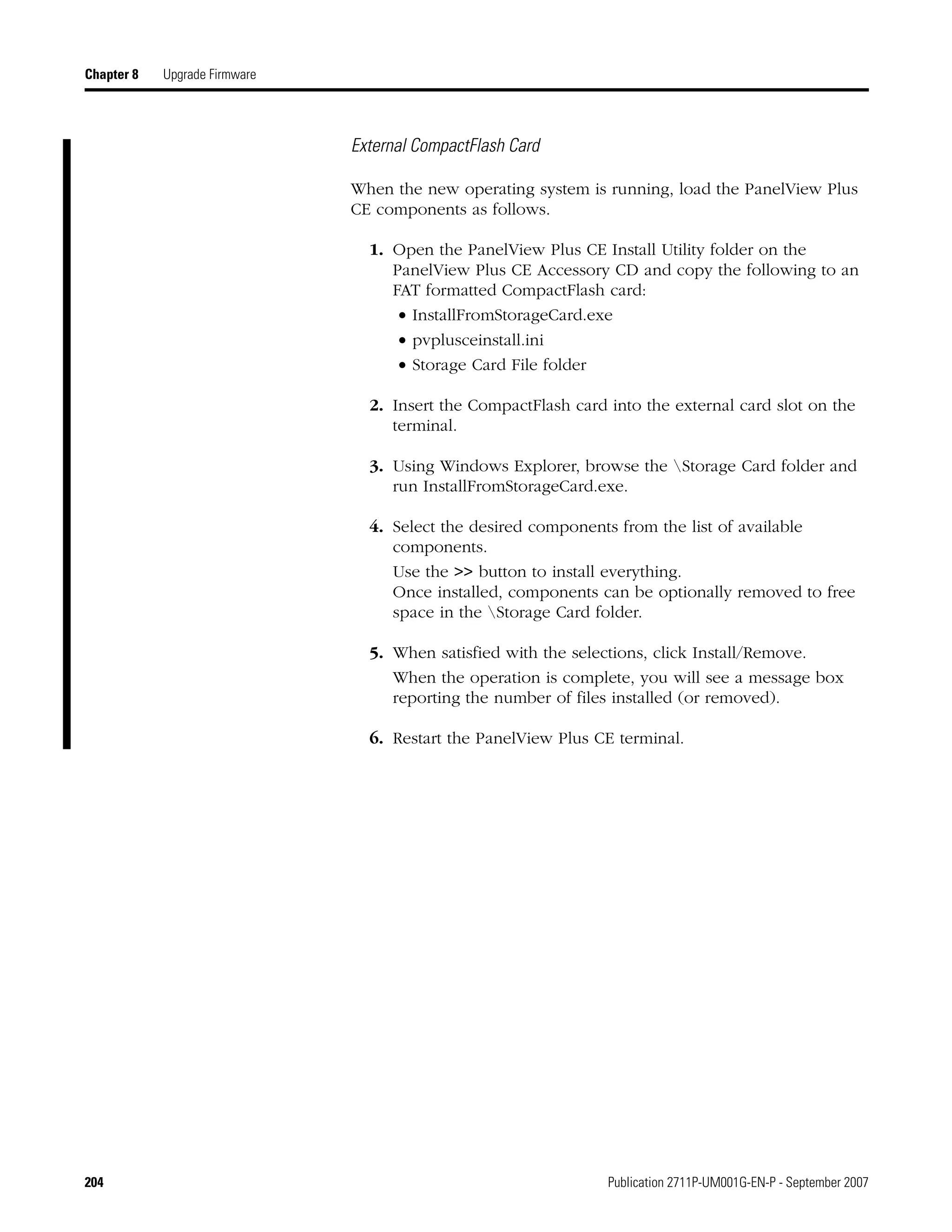
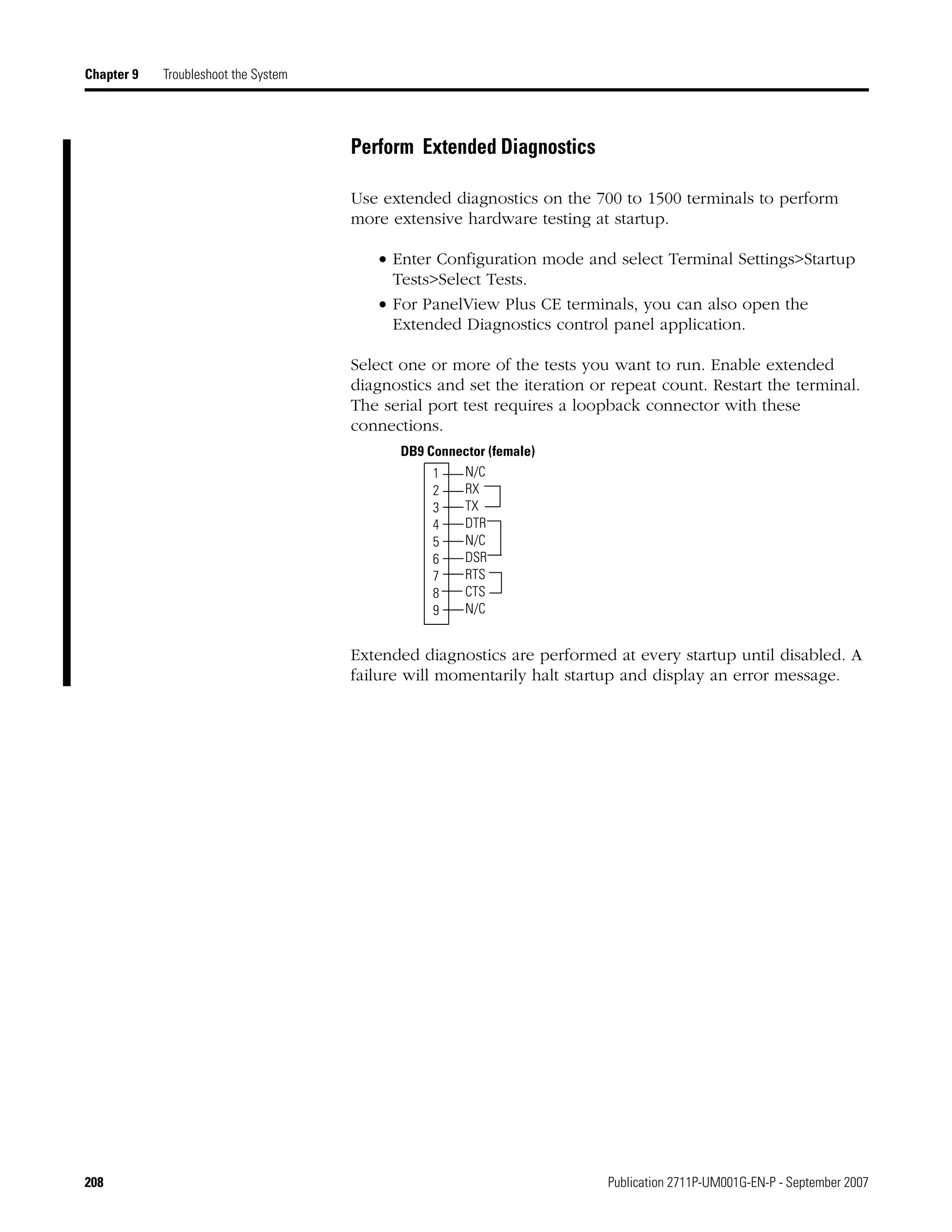
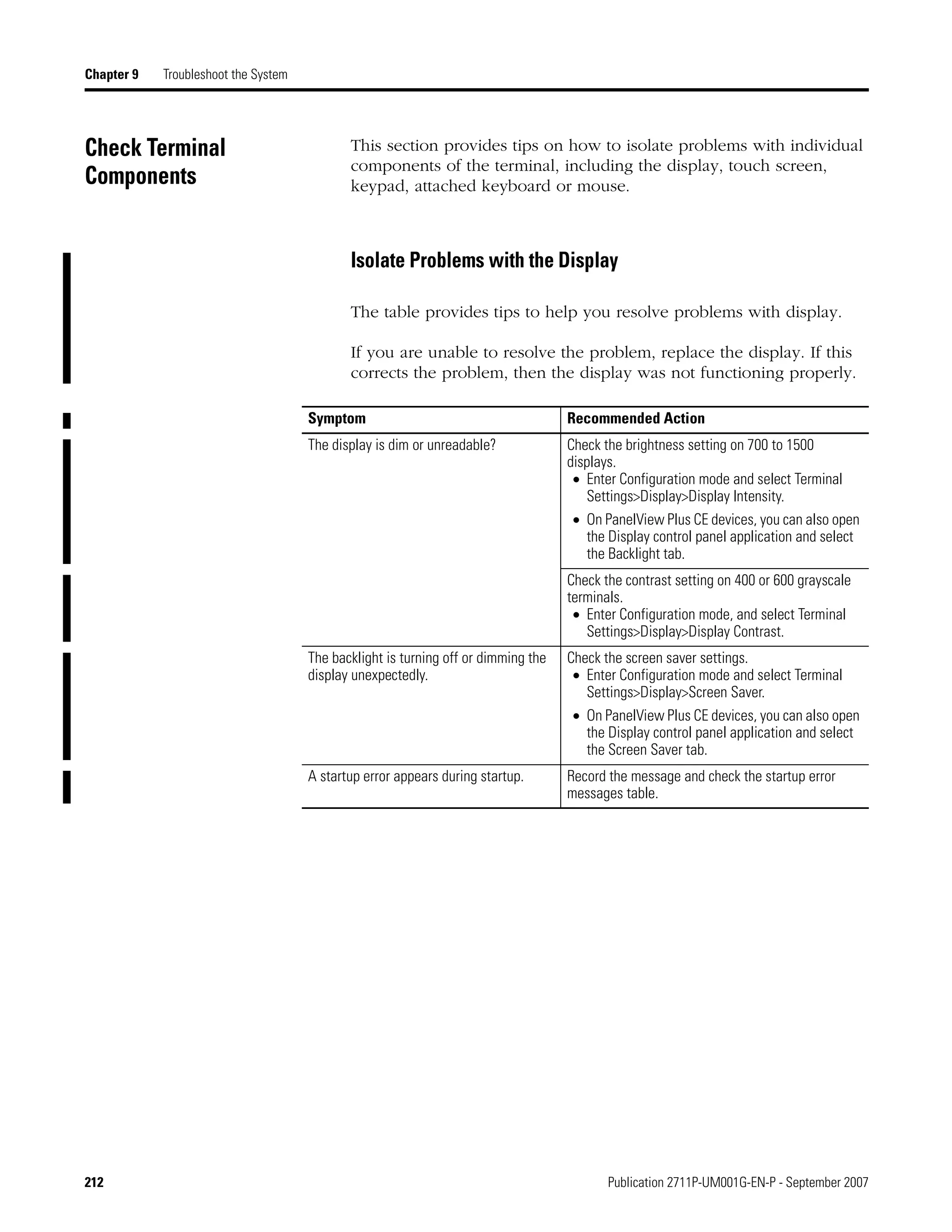
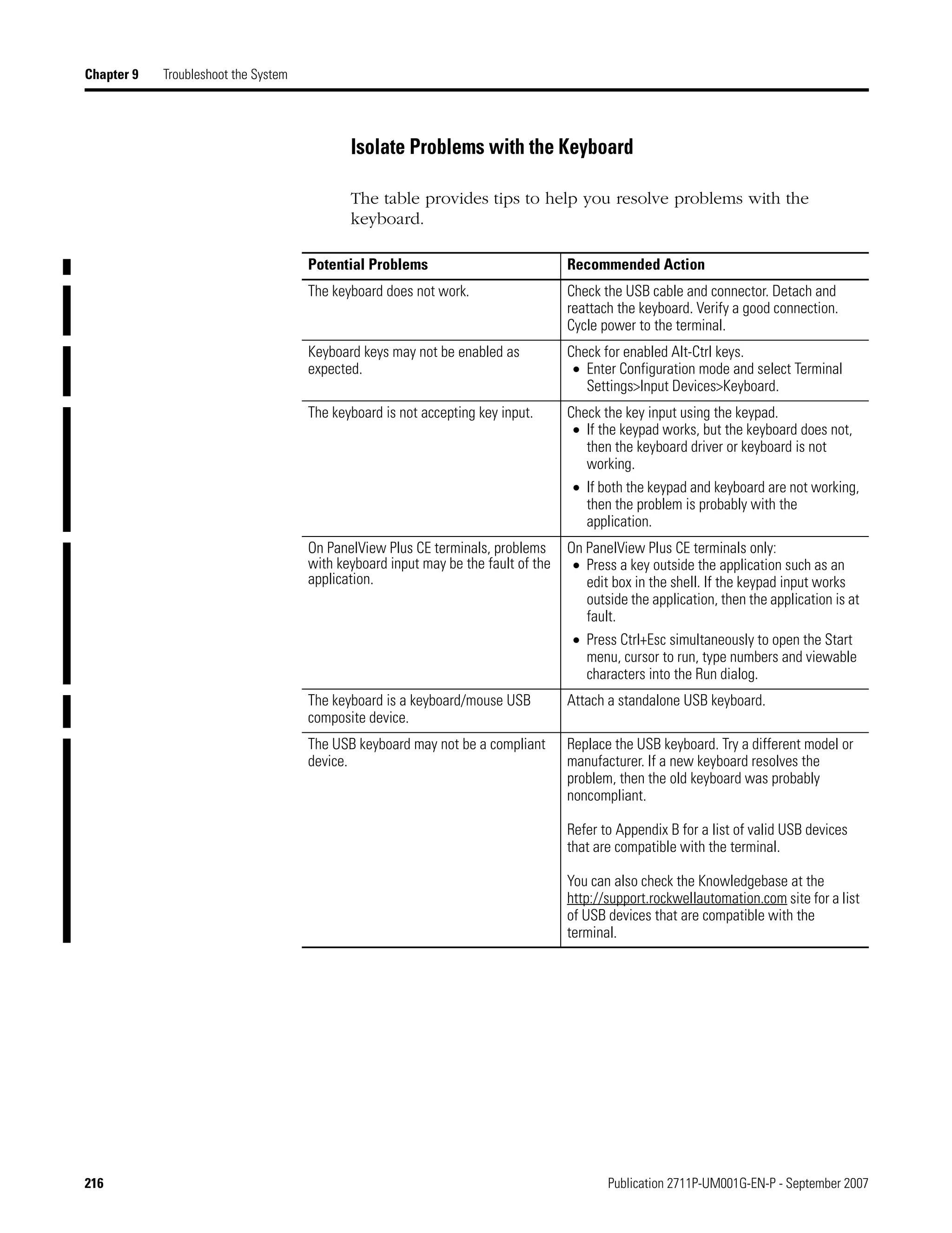
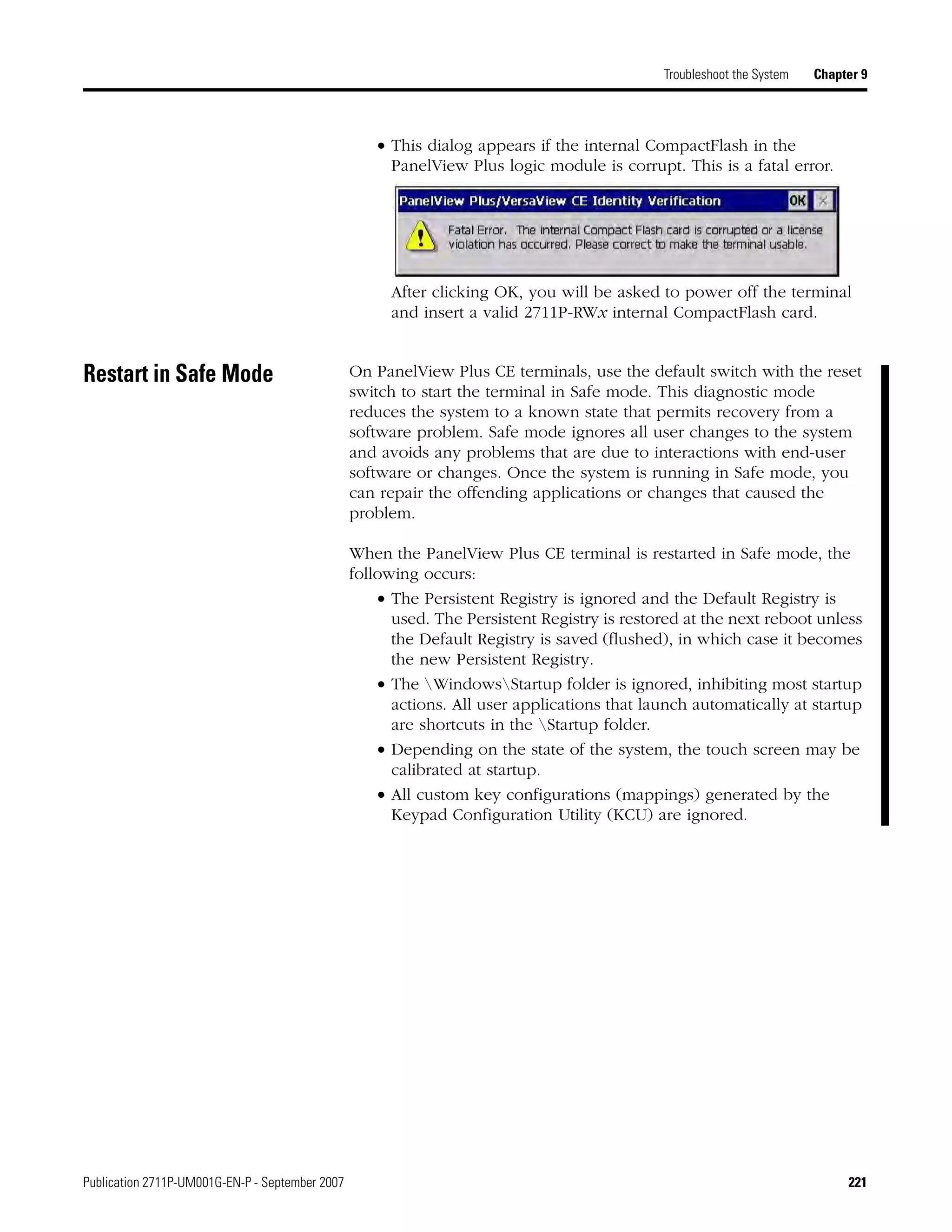
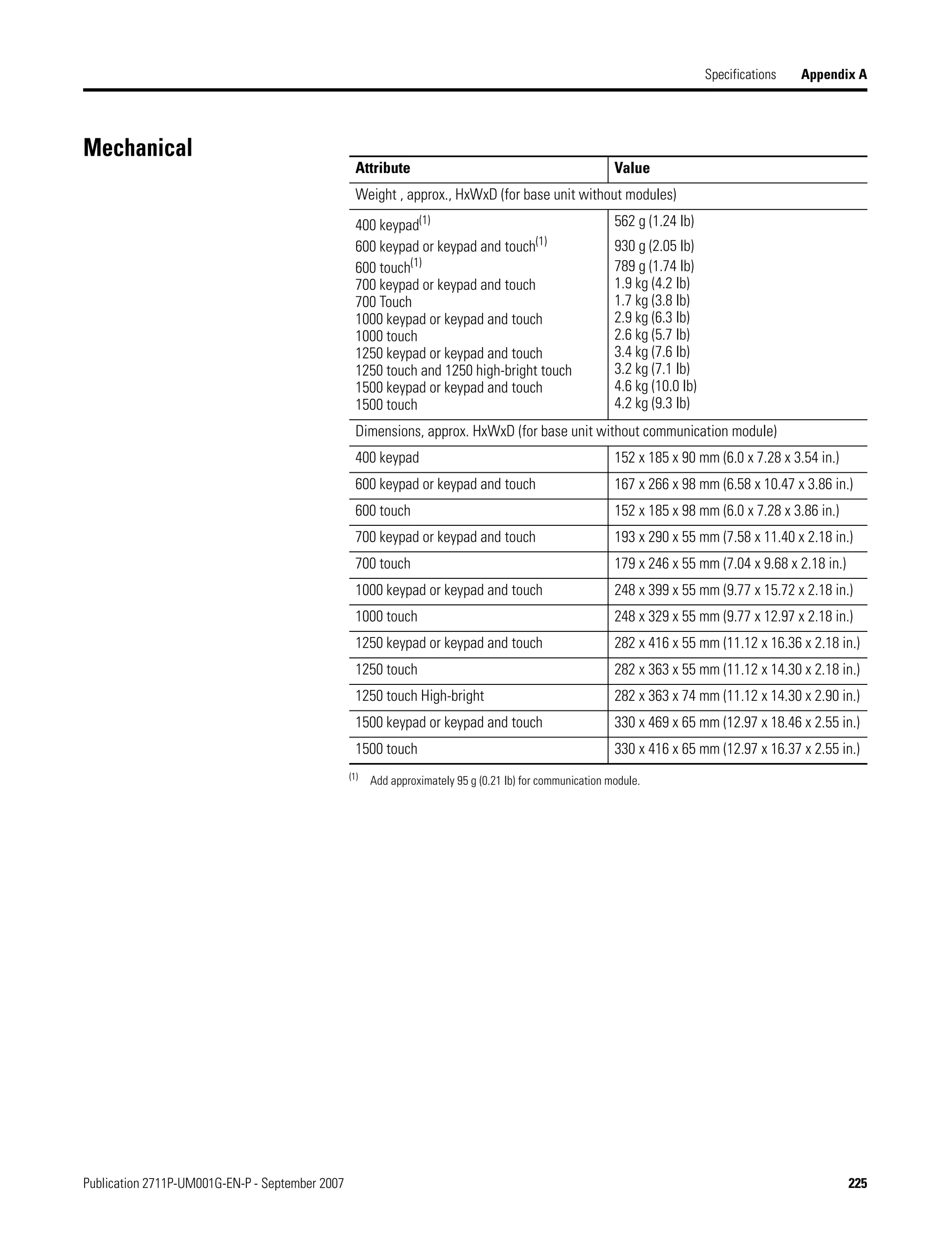
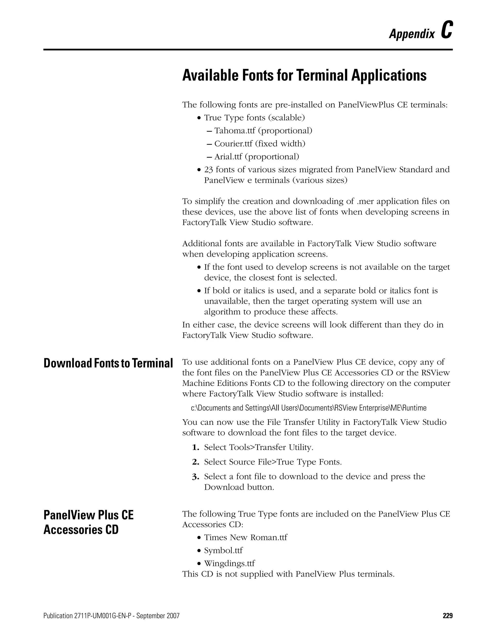
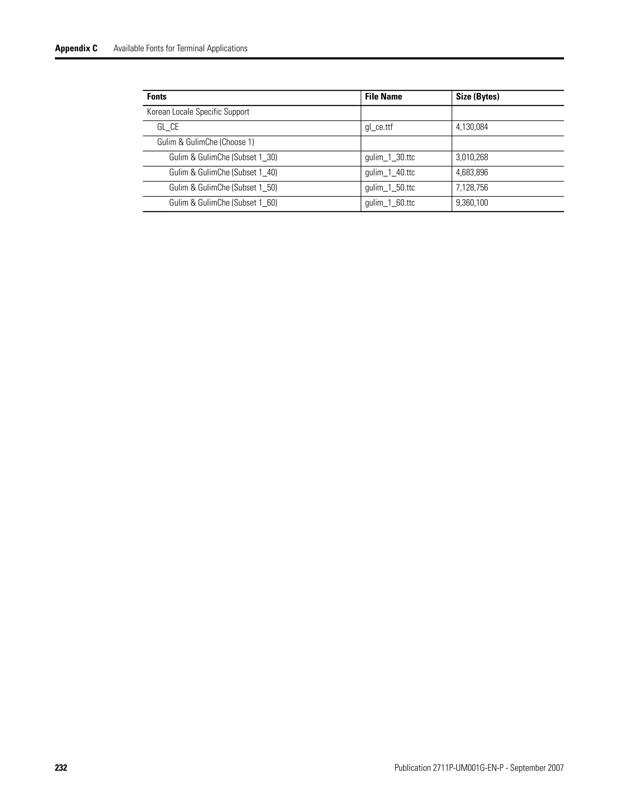
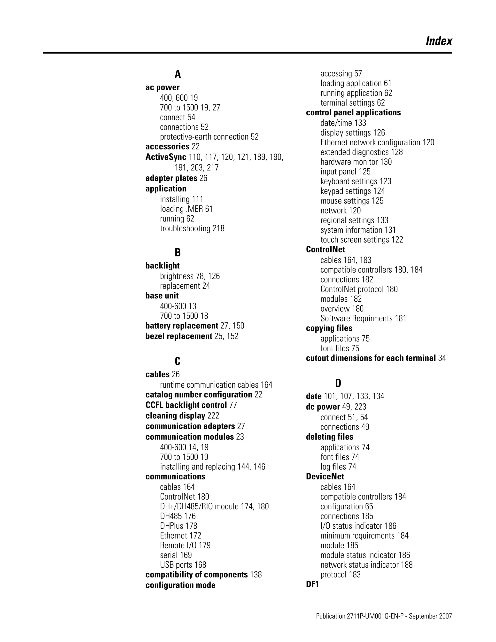
Font Linking Font linking lets you run a translated application on the terminal by
linking a font file to the base font (for example, linking a Chinese font
file to the base font Arial).
For more details on preinstalled terminal fonts and additional fonts
available for downloading, see Appendix C.
Terminal Settings
Font Linking
Arial
Courier New
Tahoma
Times New Roman
Show Links
[F1]
Close
[F8]
Courier New
MS Mincho
Tahoma
Times New Roman
Add Fonts
[F1]
Close
[F8] Close
[F8]
Delete Link
[F1]
Edit Link
[F2]
Base font = Arial
Link:
MS Mincho
External storage 1MSMINCHO.TTC
List of fonts loaded on
the terminal.
Shows the location and name of the
font that is linked to the base font
used by the terminal. If a file is not
linked, box will be empty.
Deletes linked
font file (if any).
Edits the link by letting you add the linked
file to a font loaded on the terminal.
Shows all fonts loaded on the terminal except the
base font. Select the name of the font you are
linking to the base font. Select the Add Fonts button
to link the font file for the selected font to the base
font. You will return to the Linked Fonts screen.
Select Base Font
Linked FontAdd Linked Font](https://image.slidesharecdn.com/panelviewplusmanual-150321055544-conversion-gate01/75/Panelviewplusmanual-81-2048.jpg)
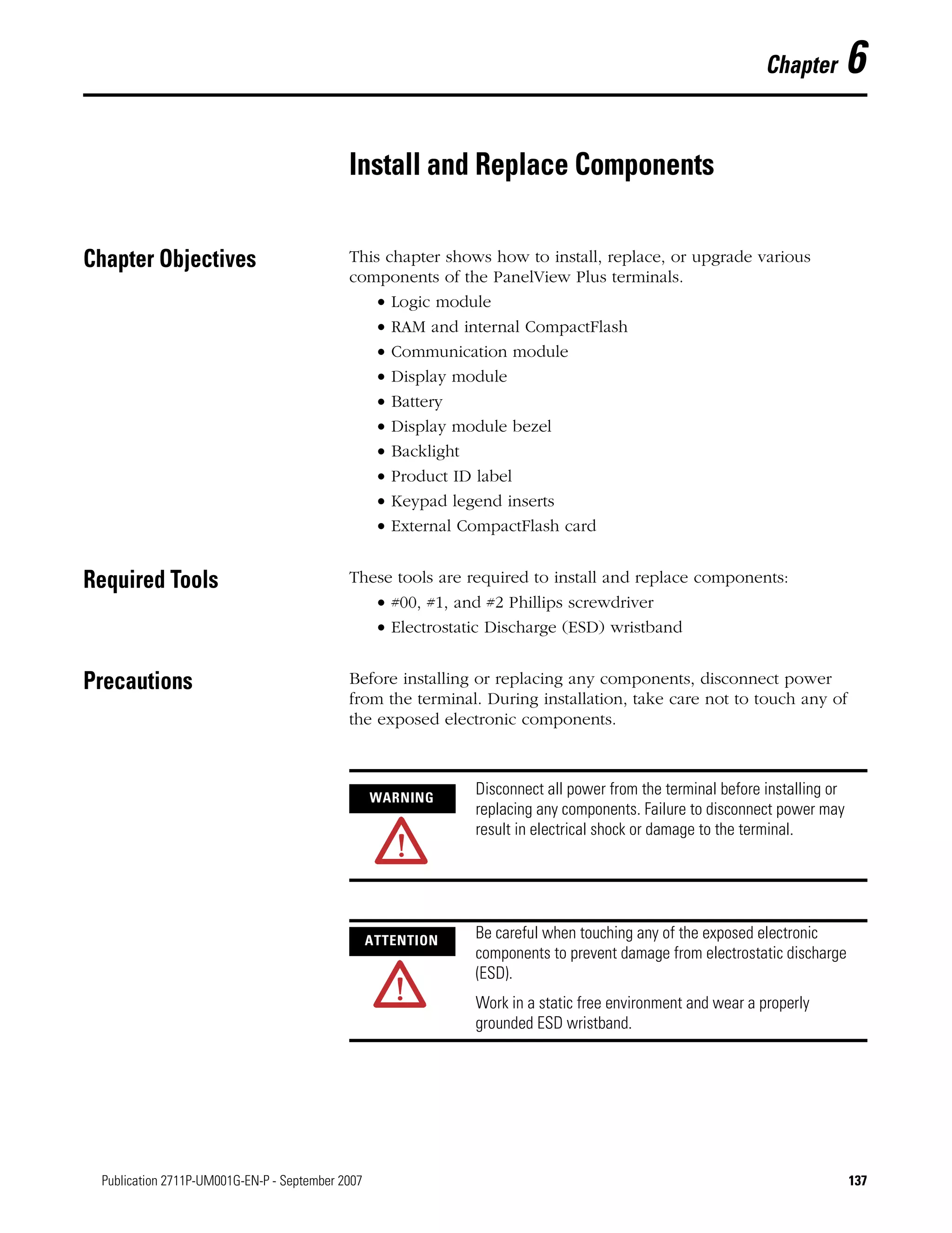
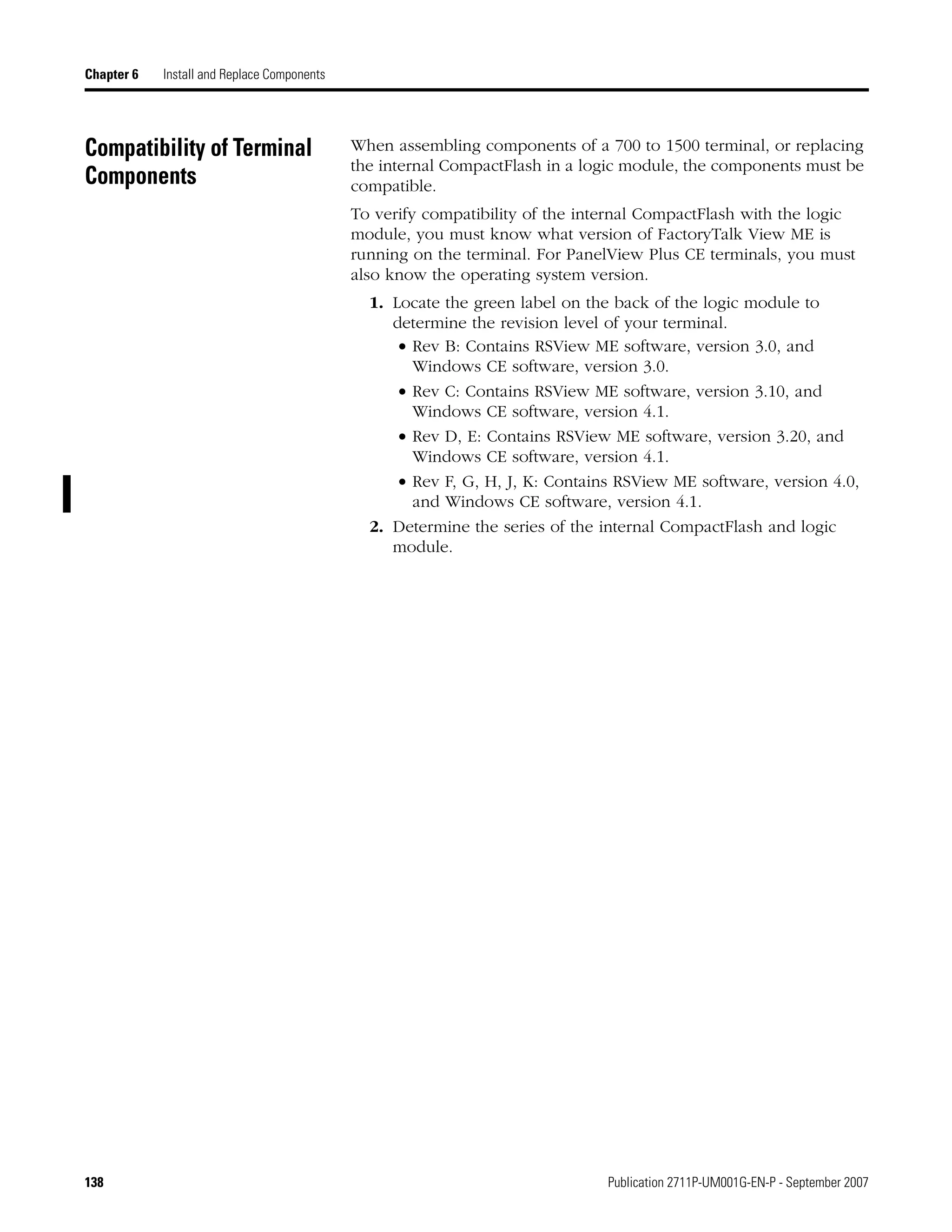
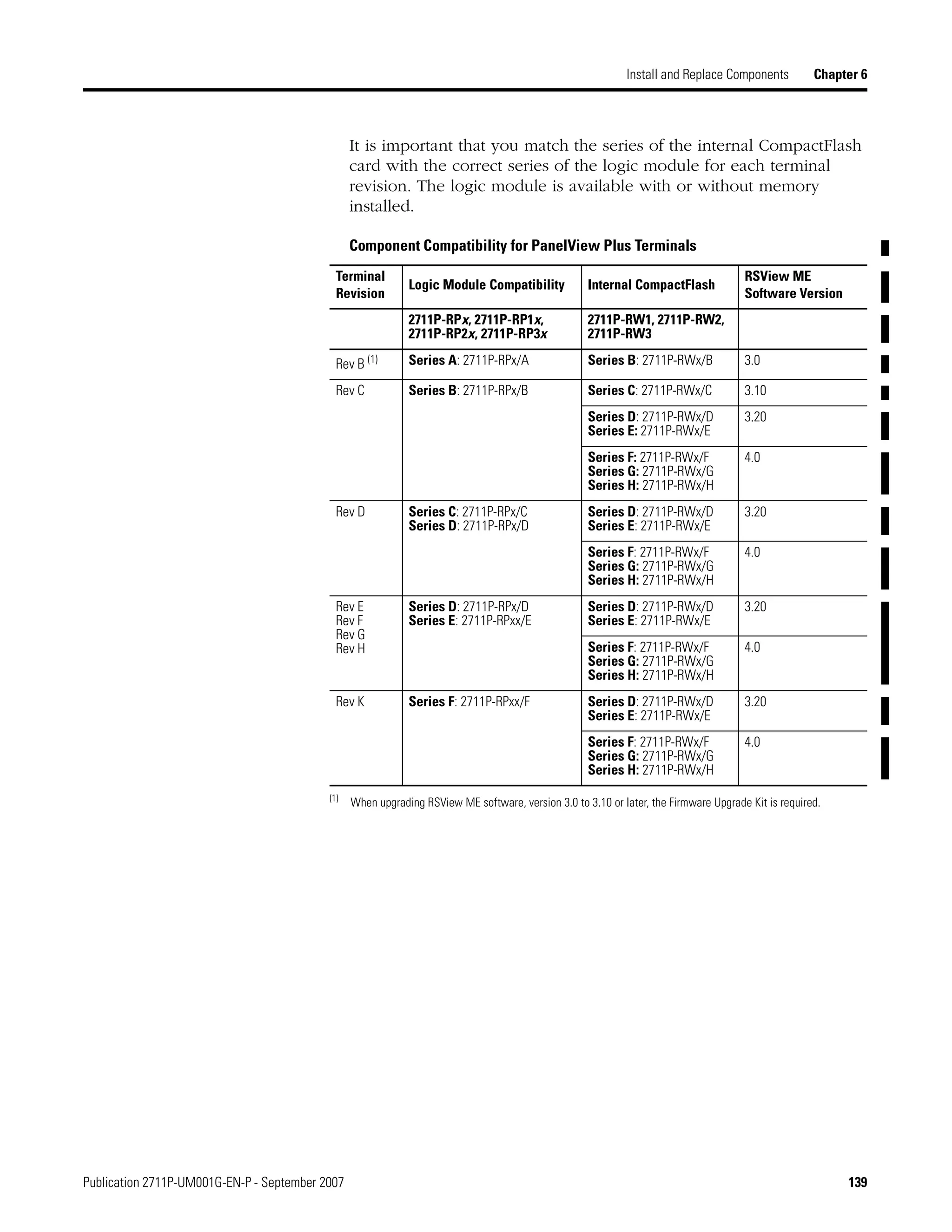
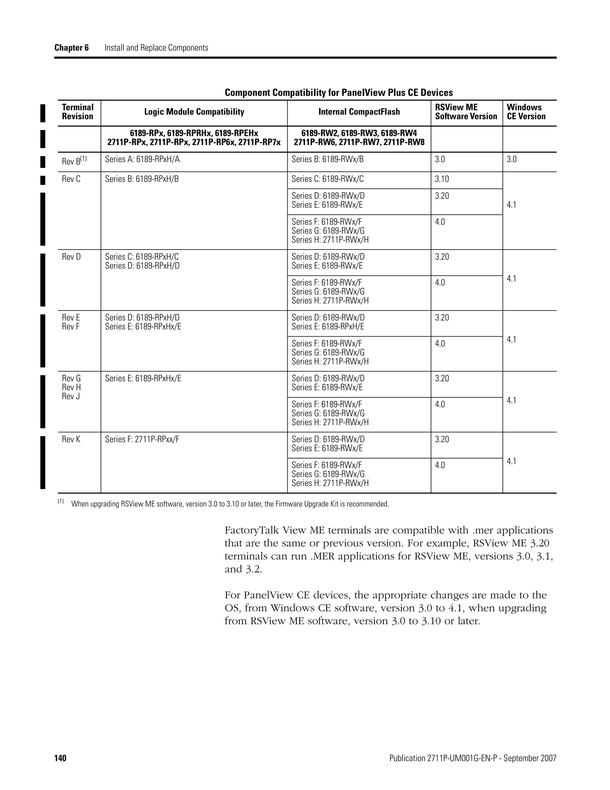


The document is a user manual for PanelView Plus terminals that provides important safety and operational information. It covers key topics such as hazardous location installation, environmental requirements, installation procedures, power connections, accessing configuration mode, and loading and running applications. The manual instructs technicians on how to properly install, configure, and operate the PanelView Plus terminals. It also provides revision details and references additional resources for further information.


![2711e um006 -en-p[1]](https://cdn.slidesharecdn.com/ss_thumbnails/2711e-um006-en-p1-120514065850-phpapp02-thumbnail.jpg?width=640&height=640&fit=bounds)


