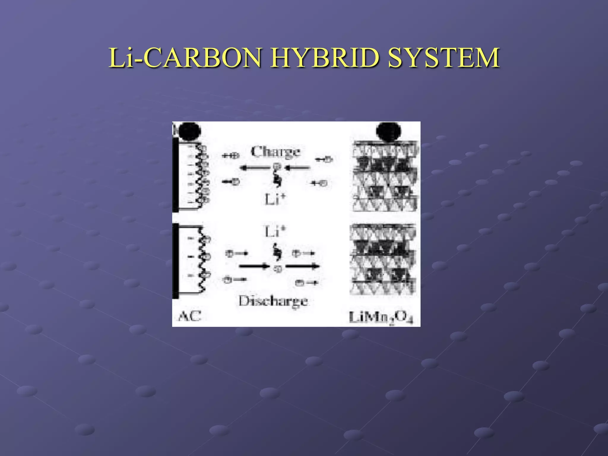
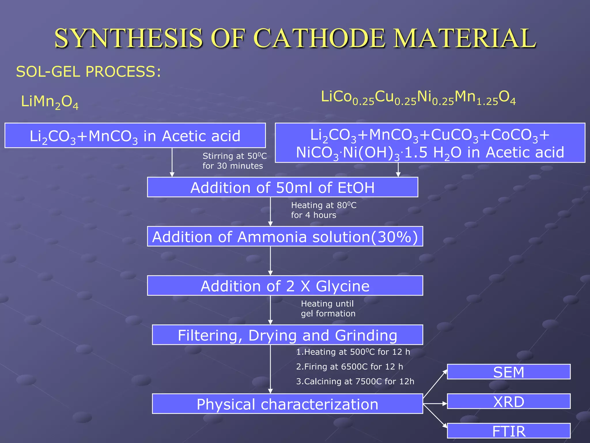
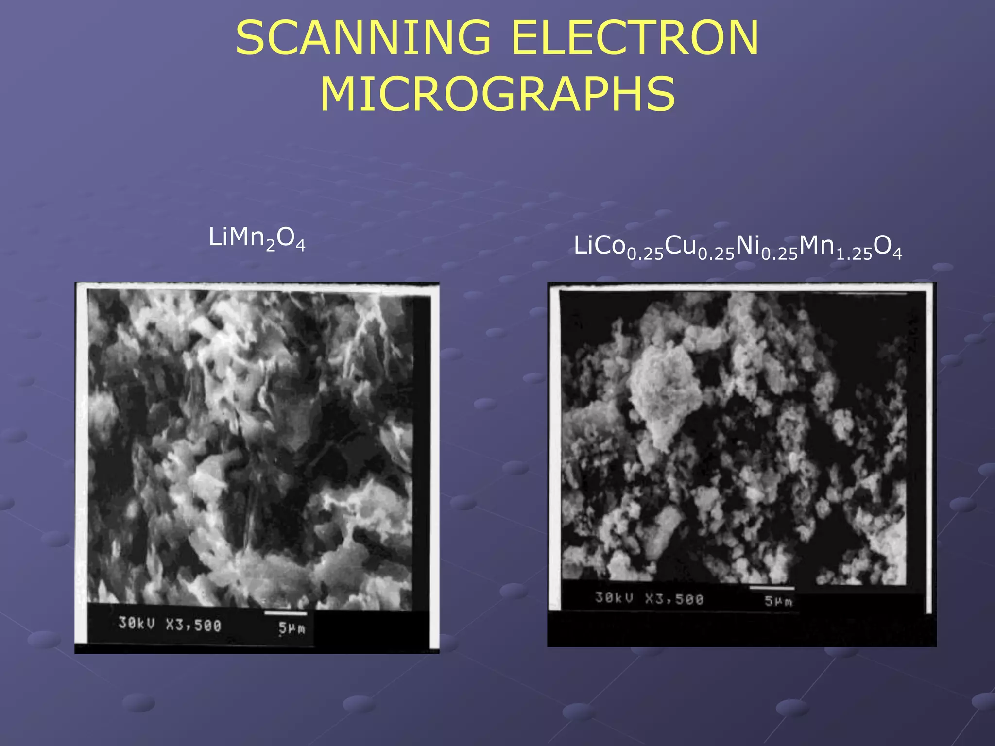
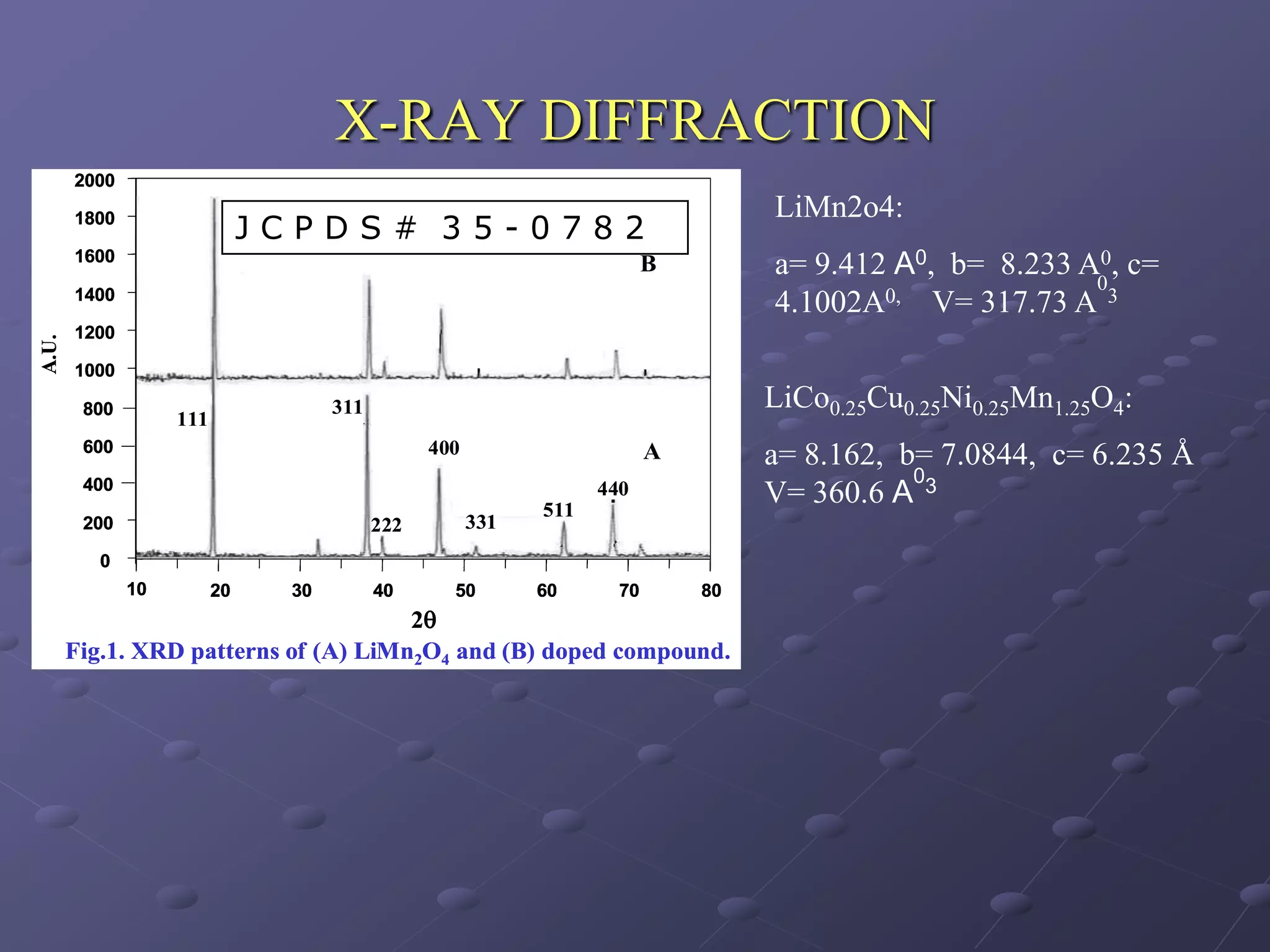
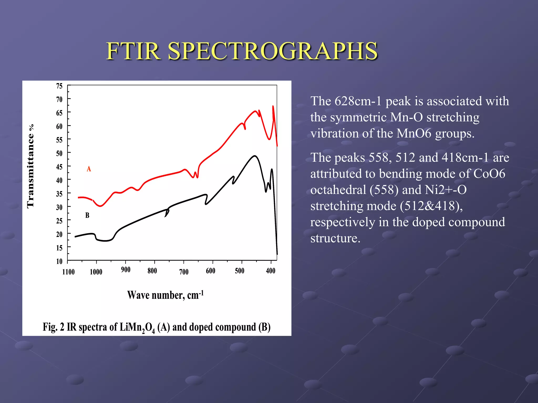
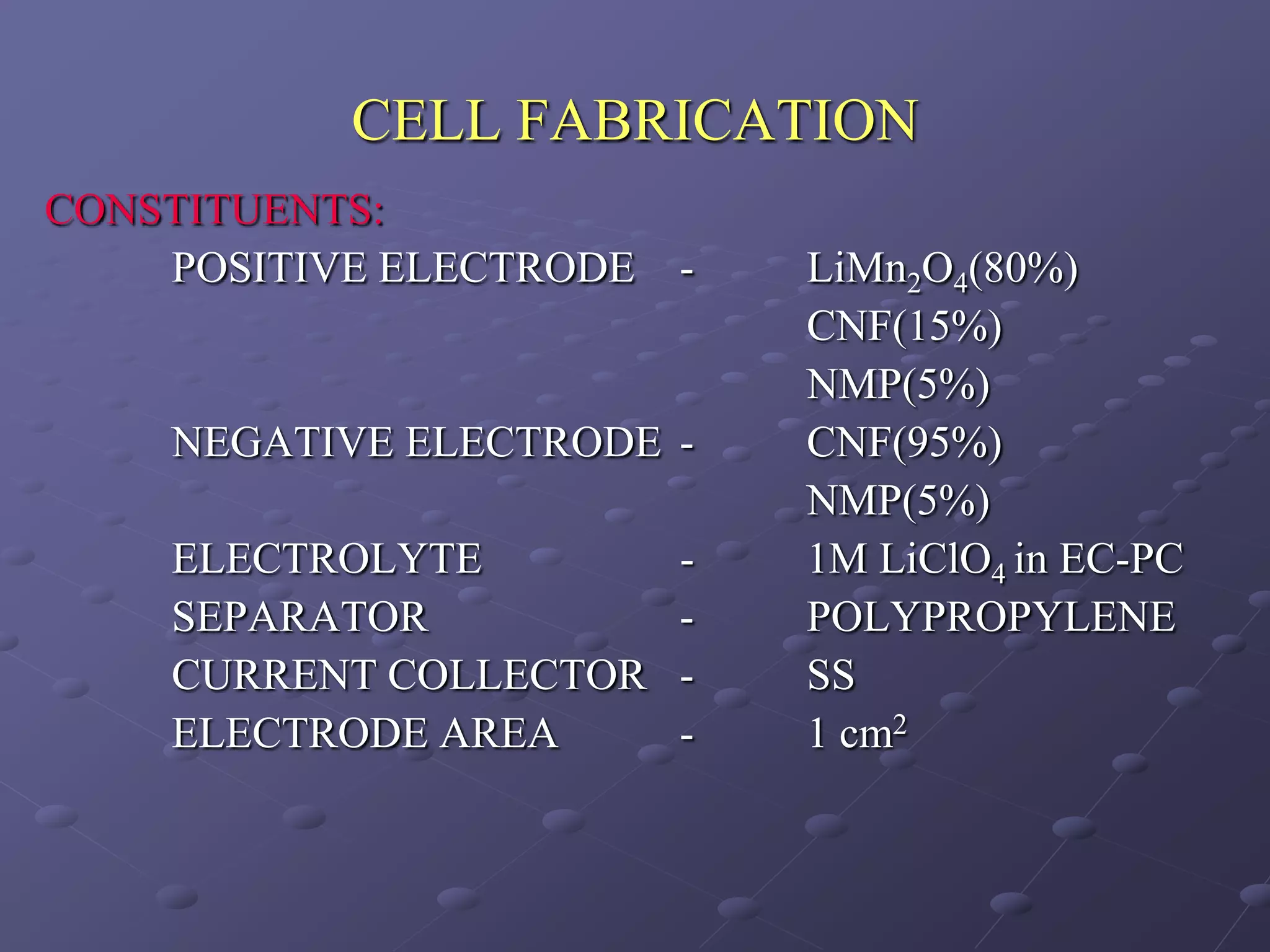
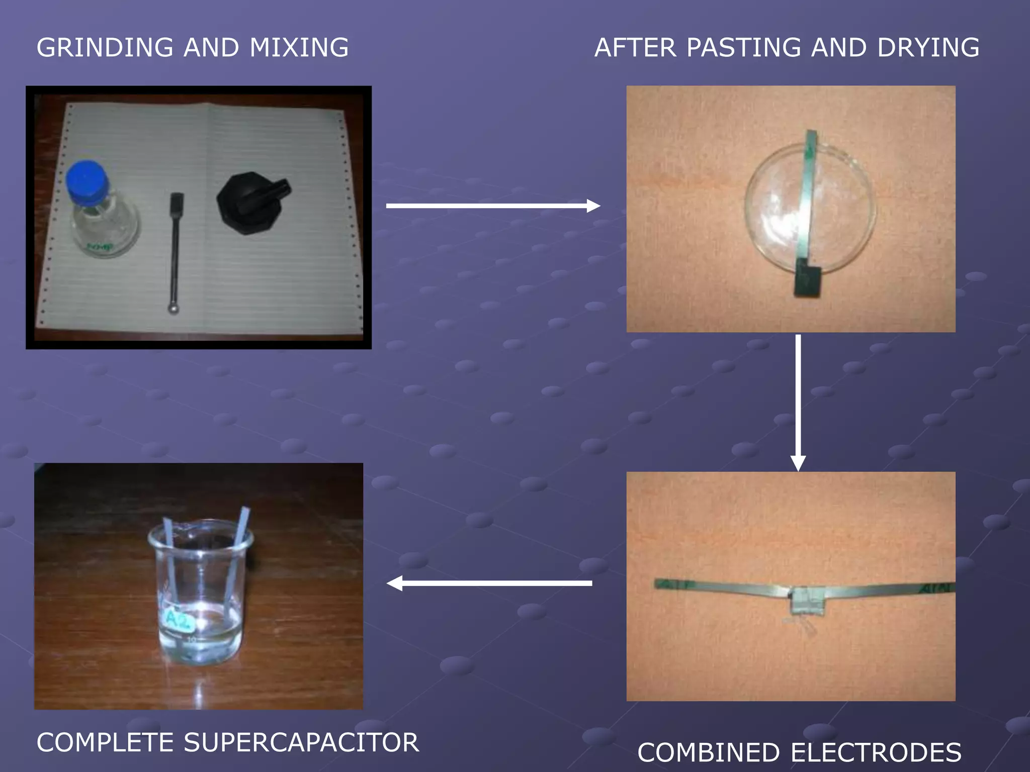
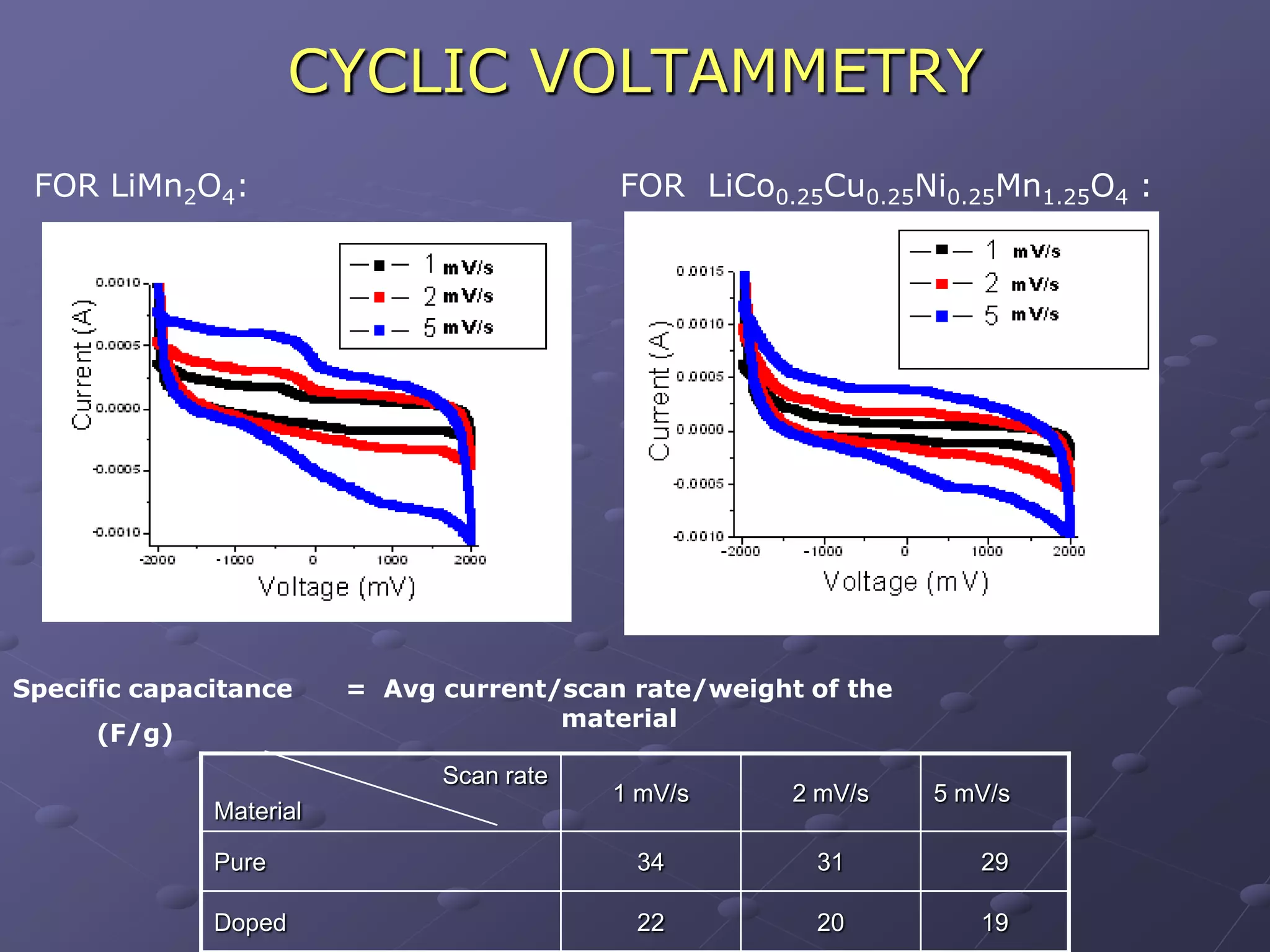
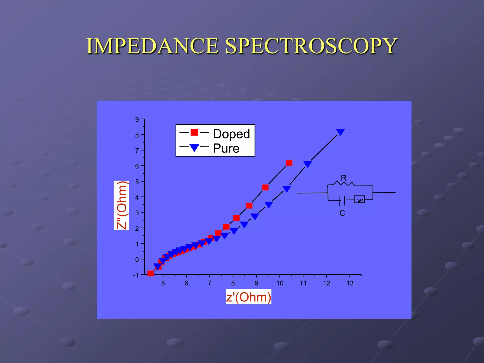
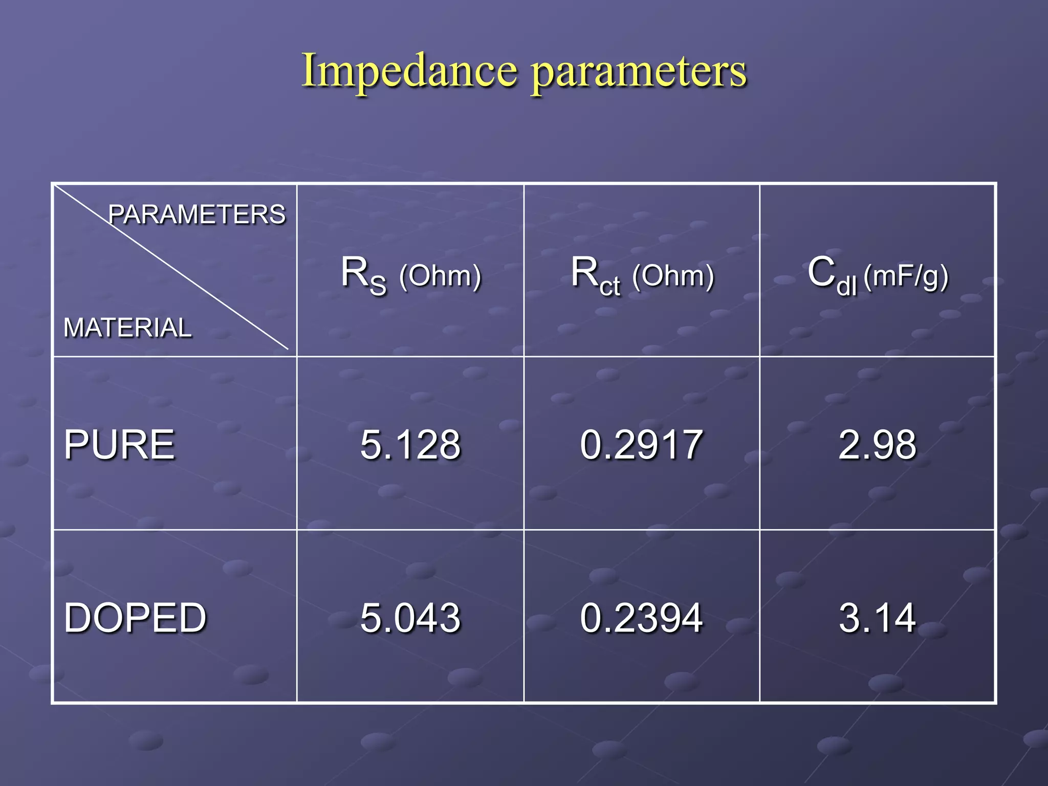
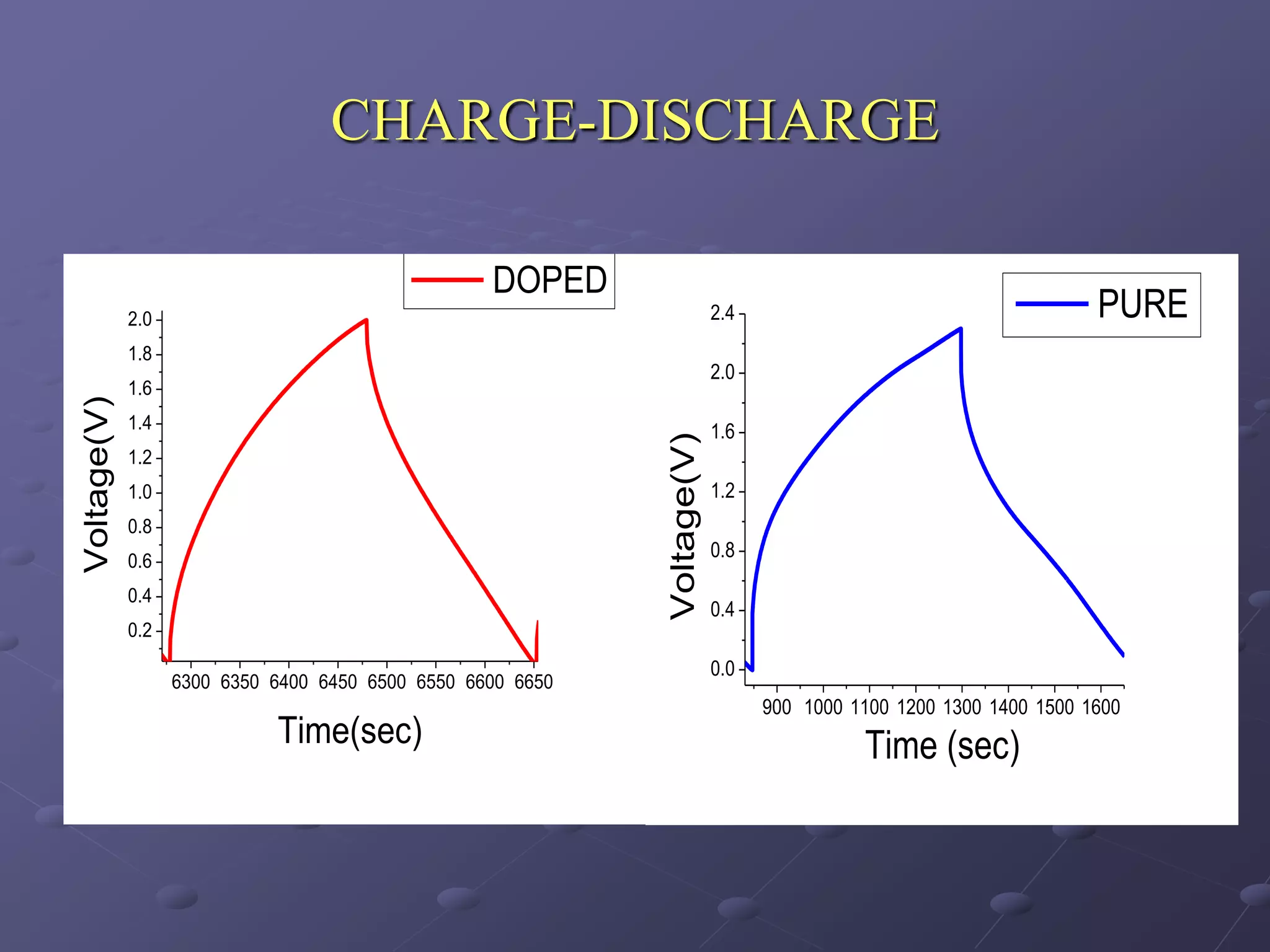
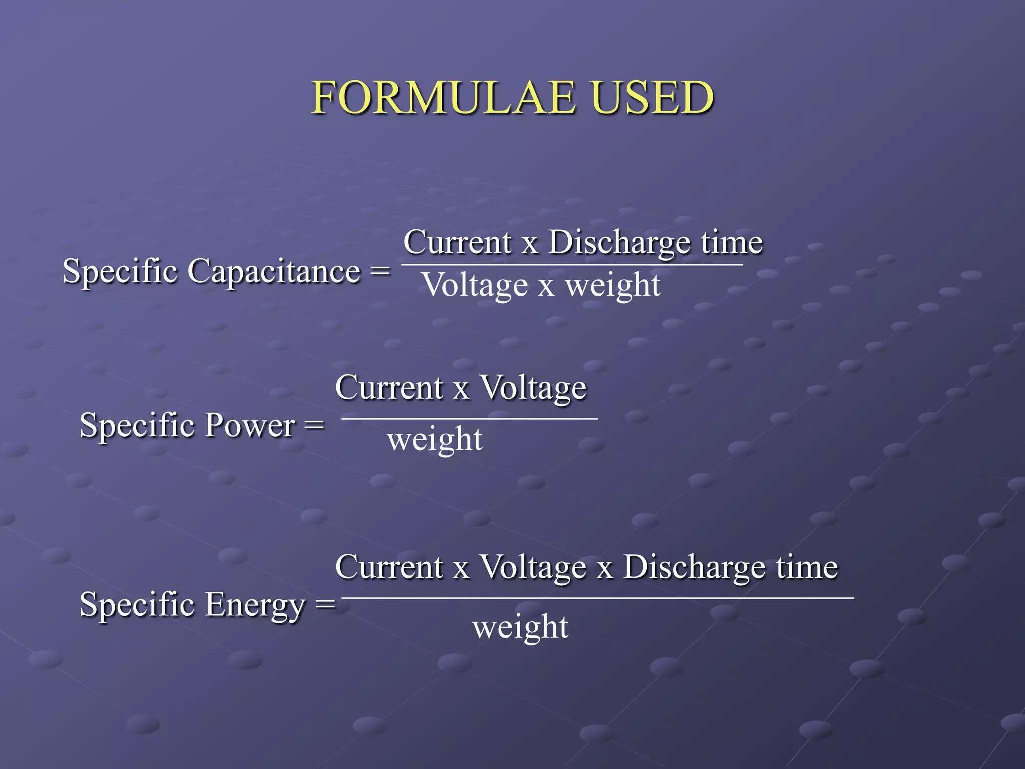
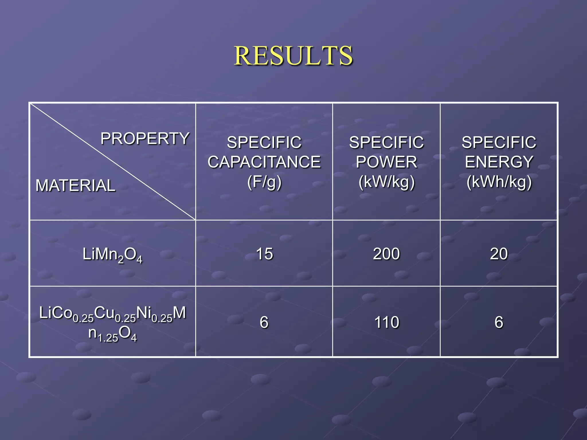
DEVELOPMENT OF NON-AQUEOUS
  ASYMMETRIC HYBRID SUPERCAPACITORS
     BASED ON Li-ION INTERCALATED
             COMPOUNDS


GUIDE
                           BY
Dr.D.KALPANA, SCIENTIST,
EEC DIVISION,
                           NAKKIRAN.A
CECRI,
KARAIKUDI.
INTRODUCTION

WHAT IS A CAPACITOR?
  capacitor is a device used for storing charges and energy in its simplest
  form.
  A capacitor consists of two conducting surfaces separated by an insulating
  material ( Dielectric).
PRINCIPLE:
What are Supercapacitors?
Supercapacitors are an advanced version of capacitors with
unique ability to combine energy storage capabilities of
batteries and power storage behavior of capacitor.
Hence fill the gap between batteries and conventional
capacitors such as the electrolyte capacitors in terms of specific
energy as well as specific power.
PROPERTIES OF ENERGY STORAGE
               DEVICES

DEVICE            CAPACITORS EDLC                  BATTERY
CHARGING TIME     μ sec – m sec   m sec - minute   Hours

DISCHARGE TIME                    m sec – minute   Minutes – months
                  μ sec – m sec
CYCLE LIFE        106 - 108       106 - 108        200-1000


SPECIFIC POWER    > 10,000        1000-3000        <500
(W/KG)
SPECIFIC ENERGY   <0.01           0.5-5            50-300
( Wh/KG)
TYPES OF SUPERCAPACITORS
1.EC DOUBLE LAYER CAPACITORS

The term electrochemical double layer capacitor is most
commonly used for carbon based double layer capacitors
because of its high capacitance value.
It generally denotes the supercapacitor having non- faradaic
reactions at both electrodes
CARBON SUPERCAPACITOR
2.PSUEDOCAPACITOR OR
           ULTRACAPACITOR
In a pseudocapacitor, there are two basic reactions, which
lead to electrochemical cell.
Both occur at the interface between a conductor and an
electrolyte and both benefits form very high specific surface
areas at the electrode.
The first mechanism commonly referred to as charge
separation, which is well documented as non-faradaic
mechanism and is the basis for EDLC.
The second reaction commonly referred to as an oxidation –
reduction reaction due faradaic mechanism.
HYBRID CAPACITOR:
             Hybrid power system is a new highly reliable
energy storage device. It is a combination of EDLC and a
battery. (eg. C and Li-ion). Hence it is known as capattery
(capacitor battery)
WHY “HYBRID”?

In supercapacitor two symmetric capacitors are connected
in series and the total capacitance is halved.

   1/Ctotal = 1/C + 1/C
     Ctotal = C/2.

But in a hybrid supercapacitor, one of the electrodes is
replaced by a battery electrode. So we can get the total
capacitance of the single capacitor electrode with the added
advantage of battery electrode.
Li-CARBON HYBRID SYSTEM
AIM

Development of hybrid power system combining various
power sources with the supercapacitors is the promising field
of research due to its fundamental advantages of both.
Our work focuses on developing a hybrid system combining
Li-ion battery and Carbon based supercapacitor.
We proposed to study the various supercapacitors based on
cathode material such as LiMn2O4, LiCoO2, LiFeP2O7 and
other such materials.
CATHODE MATERIAL

 Our work starts with making pure and doped lithium
  manganate as suitable candidate for Lithium ion based
  supercapacitor system
 Why Lithium manganate ?
            Spinel LiMn2O4 is of great interest as a cathode
  material for lithium ion batteries.
  Advantage:
 High voltage, low cost and low toxicity
  Disadvantage:
 Poor cycling behavior because of a fast capacity fading
  due to Jahn Teller distortion
JAHN TELLER DISTORTION AND ITS
            REMEDY
     Average oxidation state of the manganese in
LiMn2O4 is 3.5 and thus any small perturbation
influencing the oxidation state may alter the ratio of Mn4+
and Mn3+.
When the ratio of Mn3+ increases ,it follows a
disproportionate reaction

             2Mn3+             Mn4+ + Mn2+

and causes high solubility of spinel material into the
solution.
Remedy:
Wahihara suggest that partially substituted LiMxMn1-xO4
(M=Co, Cu, Ni, Mn) shows improved cyclability due to the
stronger M-O bonding of octahedron structure in
comparison to that of Mn-O bonding in LiMn2O4.
Hence we studied the both pure and the doped manganate
system
SYNTHESIS OF CATHODE MATERIAL
SOL-GEL PROCESS:

LiMn2O4                                         LiCo0.25Cu0.25Ni0.25Mn1.25O4

 Li2CO3+MnCO3 in Acetic acid                 Li2CO3+MnCO3+CuCO3+CoCO3+
                       Stirring at 500C    NiCO3.Ni(OH)3.1.5 H2O in Acetic acid
                       for 30 minutes

                     Addition of 50ml of EtOH
                                          Heating at 800C
                                          for 4 hours

                Addition of Ammonia solution(30%)


                      Addition of 2 X Glycine
                                            Heating until
                                            gel formation

                   Filtering, Drying and Grinding
                                           1.Heating at 5000C for 12 h
                                           2.Firing at 6500C for 12 h
                                           3.Calcining at 7500C for 12h
                                                                          SEM

                      Physical characterization                           XRD

                                                                          FTIR
SCANNING ELECTRON
    MICROGRAPHS

LiMn2O4    LiCo0.25Cu0.25Ni0.25Mn1.25O4
X-RAY DIFFRACTION
       2000
                                                                                  LiMn2o4:
       1800
                              JCPDS# 35-0782
       1600                                                              B        a= 9.412 A0, b= 8.233 A0 , c=
                                                                                                         0
       1400
                                                                                  4.1002A0, V= 317.73 A 3
       1200
A.U.


       1000

        800                         311                                           LiCo0.25Cu0.25Ni0.25Mn1.25O4:
                   111
        600                                     400                      A        a= 8.162, b= 7.0844, c= 6.235 Å
        400                                                                                  0
                                                            511
                                                                  440             V= 360.6 A 3
        200                               222         331
          0
              10         20    30         40      50        60      70       80
                                      2
       Fig.1. XRD patterns of (A) LiMn2O4 and (B) doped compound.
Pristine LiMn2O4 adopts a cubic Fd3m space group
The XRD data does not shows any structural distortion on
doping which is evident when the doping concentration
increases X<0.5
FTIR SPECTROGRAPHS
                     75
                     70                                                          The 628cm-1 peak is associated with
                     65
                                                                                 the symmetric Mn-O stretching
                     60
Transmittance %


                     55
                                                                                 vibration of the MnO6 groups.
                     50
                                                                                 The peaks 558, 512 and 418cm-1 are
                     45       A
                     40
                                                                                 attributed to bending mode of CoO6
                     35                                                          octahedral (558) and Ni2+-O
                     30                                                          stretching mode (512&418),
                              B
                     25                                                          respectively in the doped compound
                     20
                                                                                 structure.
                     15
                     10
                       1100       1000    900   800   700      600   500   400


                                           Wave number, cm-1

                  Fig. 2 IR spectra of LiMn2O4 (A) and doped compound (B)
ANODE MATERIAL
CNF – Carbon Nano Foam
  High surface area (1500 m2/g)
  Low electrical resistance
  No participation in faradaic reactions at the applied voltage
  High capacity (100 - 200 F/g)
  Unlike AC, CNF combine high surface area with high bulk
  density to give large capacitance values
CELL FABRICATION
CONSTITUENTS:
    POSITIVE ELECTRODE   -   LiMn2O4(80%)
                             CNF(15%)
                             NMP(5%)
    NEGATIVE ELECTRODE -     CNF(95%)
                             NMP(5%)
    ELECTROLYTE          -   1M LiClO4 in EC-PC
    SEPARATOR            -   POLYPROPYLENE
    CURRENT COLLECTOR    -   SS
    ELECTRODE AREA       -   1 cm2
GRINDING AND MIXING       AFTER PASTING AND DRYING


COMPLETE SUPERCAPACITOR     COMBINED ELECTRODES
ELECTROCHEMICAL CHARACTERIZATION

      1.   Electrochemical Impedance
           spectroscopy
      2.   Cyclic voltammetry
      3.   Galvanostatic charge / Discharge
CYCLIC VOLTAMMETRY
 FOR LiMn2O4:                              FOR LiCo0.25Cu0.25Ni0.25Mn1.25O4 :


Specific capacitance     = Avg current/scan rate/weight of the
                                       material
     (F/g)
                               Scan rate
                                           1 mV/s      2 mV/s    5 mV/s
              Material

              Pure                          34          31          29

              Doped                         22          20          19
IMPEDANCE SPECTROSCOPY


             9

             8                Doped
             7                Pure
             6

             5
                                                         R
  Z''(Ohm)


             4
                                                                  w
             3                                           C
             2

             1

             0

             -1
                  5   6   7     8     9   10   11   12       13

                               z'(Ohm)
Impedance parameters

  PARAMETERS

                RS (Ohm)   Rct (Ohm)   Cdl (mF/g)
MATERIAL


PURE             5.128     0.2917        2.98


DOPED            5.043     0.2394        3.14
CHARGE-DISCHARGE

                                                   DOPED
             2.0                                                          2.4                                      PURE
             1.8
                                                                          2.0
             1.6
Voltage(V)


             1.4                                                          1.6


                                                             Voltage(V)
             1.2
             1.0                                                          1.2
             0.8
             0.6
                                                                          0.8

             0.4
                                                                          0.4
             0.2
                                                                          0.0
                   6300 6350 6400 6450 6500 6550 6600 6650
                                                                                900 1000 1100 1200 1300 1400 1500 1600
                             Time(sec)                                                    Time (sec)
FORMULAE USED

                      Current x Discharge time
Specific Capacitance = Voltage x weight


                  Current x Voltage
 Specific Power =    weight


                  Current x Voltage x Discharge time
 Specific Energy =
                           weight
RESULTS

        PROPERTY          SPECIFIC    SPECIFIC   SPECIFIC
                        CAPACITANCE    POWER     ENERGY
MATERIAL                    (F/g)      (kW/kg)   (kWh/kg)


      LiMn2O4               15          200         20


LiCo0.25Cu0.25Ni0.25M
                             6          110         6
       n1.25O4
FUTURE WORK

Finding the cycle life behavior of this capacitor and
variation of properties with cycle life.
Continuing the same work for the LiCoO2 cathode material
prepared by various methods and comparing their results
with the results of LiMn2O4.
THANK YOU
QUERIES ?

Development Of Non Aqueous Asymmetric Hybrid Supercapacitors Part I

  • 1.
    DEVELOPMENT OF NON-AQUEOUS ASYMMETRIC HYBRID SUPERCAPACITORS BASED ON Li-ION INTERCALATED COMPOUNDS GUIDE BY Dr.D.KALPANA, SCIENTIST, EEC DIVISION, NAKKIRAN.A CECRI, KARAIKUDI.
  • 2.
    INTRODUCTION WHAT IS ACAPACITOR? capacitor is a device used for storing charges and energy in its simplest form. A capacitor consists of two conducting surfaces separated by an insulating material ( Dielectric). PRINCIPLE:
  • 4.
    What are Supercapacitors? Supercapacitorsare an advanced version of capacitors with unique ability to combine energy storage capabilities of batteries and power storage behavior of capacitor. Hence fill the gap between batteries and conventional capacitors such as the electrolyte capacitors in terms of specific energy as well as specific power.
  • 5.
    PROPERTIES OF ENERGYSTORAGE DEVICES DEVICE CAPACITORS EDLC BATTERY CHARGING TIME μ sec – m sec m sec - minute Hours DISCHARGE TIME m sec – minute Minutes – months μ sec – m sec CYCLE LIFE 106 - 108 106 - 108 200-1000 SPECIFIC POWER > 10,000 1000-3000 <500 (W/KG) SPECIFIC ENERGY <0.01 0.5-5 50-300 ( Wh/KG)
  • 6.
  • 7.
    1.EC DOUBLE LAYERCAPACITORS The term electrochemical double layer capacitor is most commonly used for carbon based double layer capacitors because of its high capacitance value. It generally denotes the supercapacitor having non- faradaic reactions at both electrodes
  • 8.
  • 10.
    2.PSUEDOCAPACITOR OR ULTRACAPACITOR In a pseudocapacitor, there are two basic reactions, which lead to electrochemical cell. Both occur at the interface between a conductor and an electrolyte and both benefits form very high specific surface areas at the electrode. The first mechanism commonly referred to as charge separation, which is well documented as non-faradaic mechanism and is the basis for EDLC. The second reaction commonly referred to as an oxidation – reduction reaction due faradaic mechanism.
  • 12.
    HYBRID CAPACITOR: Hybrid power system is a new highly reliable energy storage device. It is a combination of EDLC and a battery. (eg. C and Li-ion). Hence it is known as capattery (capacitor battery)
  • 13.
    WHY “HYBRID”? In supercapacitortwo symmetric capacitors are connected in series and the total capacitance is halved. 1/Ctotal = 1/C + 1/C Ctotal = C/2. But in a hybrid supercapacitor, one of the electrodes is replaced by a battery electrode. So we can get the total capacitance of the single capacitor electrode with the added advantage of battery electrode.
  • 14.
  • 16.
    AIM Development of hybridpower system combining various power sources with the supercapacitors is the promising field of research due to its fundamental advantages of both. Our work focuses on developing a hybrid system combining Li-ion battery and Carbon based supercapacitor. We proposed to study the various supercapacitors based on cathode material such as LiMn2O4, LiCoO2, LiFeP2O7 and other such materials.
  • 17.
    CATHODE MATERIAL  Ourwork starts with making pure and doped lithium manganate as suitable candidate for Lithium ion based supercapacitor system  Why Lithium manganate ? Spinel LiMn2O4 is of great interest as a cathode material for lithium ion batteries. Advantage:  High voltage, low cost and low toxicity Disadvantage:  Poor cycling behavior because of a fast capacity fading due to Jahn Teller distortion
  • 18.
    JAHN TELLER DISTORTIONAND ITS REMEDY Average oxidation state of the manganese in LiMn2O4 is 3.5 and thus any small perturbation influencing the oxidation state may alter the ratio of Mn4+ and Mn3+. When the ratio of Mn3+ increases ,it follows a disproportionate reaction 2Mn3+ Mn4+ + Mn2+ and causes high solubility of spinel material into the solution.
  • 19.
    Remedy: Wahihara suggest thatpartially substituted LiMxMn1-xO4 (M=Co, Cu, Ni, Mn) shows improved cyclability due to the stronger M-O bonding of octahedron structure in comparison to that of Mn-O bonding in LiMn2O4. Hence we studied the both pure and the doped manganate system
  • 20.
    SYNTHESIS OF CATHODEMATERIAL SOL-GEL PROCESS: LiMn2O4 LiCo0.25Cu0.25Ni0.25Mn1.25O4 Li2CO3+MnCO3 in Acetic acid Li2CO3+MnCO3+CuCO3+CoCO3+ Stirring at 500C NiCO3.Ni(OH)3.1.5 H2O in Acetic acid for 30 minutes Addition of 50ml of EtOH Heating at 800C for 4 hours Addition of Ammonia solution(30%) Addition of 2 X Glycine Heating until gel formation Filtering, Drying and Grinding 1.Heating at 5000C for 12 h 2.Firing at 6500C for 12 h 3.Calcining at 7500C for 12h SEM Physical characterization XRD FTIR
  • 21.
    SCANNING ELECTRON MICROGRAPHS LiMn2O4 LiCo0.25Cu0.25Ni0.25Mn1.25O4
  • 22.
    X-RAY DIFFRACTION 2000 LiMn2o4: 1800 JCPDS# 35-0782 1600 B a= 9.412 A0, b= 8.233 A0 , c= 0 1400 4.1002A0, V= 317.73 A 3 1200 A.U. 1000 800 311 LiCo0.25Cu0.25Ni0.25Mn1.25O4: 111 600 400 A a= 8.162, b= 7.0844, c= 6.235 Å 400 0 511 440 V= 360.6 A 3 200 222 331 0 10 20 30 40 50 60 70 80 2 Fig.1. XRD patterns of (A) LiMn2O4 and (B) doped compound.
  • 23.
    Pristine LiMn2O4 adoptsa cubic Fd3m space group The XRD data does not shows any structural distortion on doping which is evident when the doping concentration increases X<0.5
  • 24.
    FTIR SPECTROGRAPHS 75 70 The 628cm-1 peak is associated with 65 the symmetric Mn-O stretching 60 Transmittance % 55 vibration of the MnO6 groups. 50 The peaks 558, 512 and 418cm-1 are 45 A 40 attributed to bending mode of CoO6 35 octahedral (558) and Ni2+-O 30 stretching mode (512&418), B 25 respectively in the doped compound 20 structure. 15 10 1100 1000 900 800 700 600 500 400 Wave number, cm-1 Fig. 2 IR spectra of LiMn2O4 (A) and doped compound (B)
  • 25.
    ANODE MATERIAL CNF –Carbon Nano Foam High surface area (1500 m2/g) Low electrical resistance No participation in faradaic reactions at the applied voltage High capacity (100 - 200 F/g) Unlike AC, CNF combine high surface area with high bulk density to give large capacitance values
  • 26.
    CELL FABRICATION CONSTITUENTS: POSITIVE ELECTRODE - LiMn2O4(80%) CNF(15%) NMP(5%) NEGATIVE ELECTRODE - CNF(95%) NMP(5%) ELECTROLYTE - 1M LiClO4 in EC-PC SEPARATOR - POLYPROPYLENE CURRENT COLLECTOR - SS ELECTRODE AREA - 1 cm2
  • 27.
    GRINDING AND MIXING AFTER PASTING AND DRYING COMPLETE SUPERCAPACITOR COMBINED ELECTRODES
  • 28.
    ELECTROCHEMICAL CHARACTERIZATION 1. Electrochemical Impedance spectroscopy 2. Cyclic voltammetry 3. Galvanostatic charge / Discharge
  • 29.
    CYCLIC VOLTAMMETRY FORLiMn2O4: FOR LiCo0.25Cu0.25Ni0.25Mn1.25O4 : Specific capacitance = Avg current/scan rate/weight of the material (F/g) Scan rate 1 mV/s 2 mV/s 5 mV/s Material Pure 34 31 29 Doped 22 20 19
  • 30.
    IMPEDANCE SPECTROSCOPY 9 8 Doped 7 Pure 6 5 R Z''(Ohm) 4 w 3 C 2 1 0 -1 5 6 7 8 9 10 11 12 13 z'(Ohm)
  • 31.
    Impedance parameters PARAMETERS RS (Ohm) Rct (Ohm) Cdl (mF/g) MATERIAL PURE 5.128 0.2917 2.98 DOPED 5.043 0.2394 3.14
  • 32.
    CHARGE-DISCHARGE DOPED 2.0 2.4 PURE 1.8 2.0 1.6 Voltage(V) 1.4 1.6 Voltage(V) 1.2 1.0 1.2 0.8 0.6 0.8 0.4 0.4 0.2 0.0 6300 6350 6400 6450 6500 6550 6600 6650 900 1000 1100 1200 1300 1400 1500 1600 Time(sec) Time (sec)
  • 33.
    FORMULAE USED Current x Discharge time Specific Capacitance = Voltage x weight Current x Voltage Specific Power = weight Current x Voltage x Discharge time Specific Energy = weight
  • 34.
    RESULTS PROPERTY SPECIFIC SPECIFIC SPECIFIC CAPACITANCE POWER ENERGY MATERIAL (F/g) (kW/kg) (kWh/kg) LiMn2O4 15 200 20 LiCo0.25Cu0.25Ni0.25M 6 110 6 n1.25O4
  • 35.
    FUTURE WORK Finding thecycle life behavior of this capacitor and variation of properties with cycle life. Continuing the same work for the LiCoO2 cathode material prepared by various methods and comparing their results with the results of LiMn2O4.
  • 36.
  • 37.